

Ijraset Journal For Research in Applied Science and Engineering Technology
Air-Cooled Heat Exchangers as a Heat Sink: Heat Transfer
Authors: Sunil Shinde, Kripa Naik, Bhagyesh Mahajan, Parag Bonde, Adithya Krishna, Toshvi Patade, Atharv Kadam
DOI Link: https://doi.org/10.22214/ijraset.2024.65659
Certificate: View Certificate
Abstract
This paper discusses heat transfer concepts in air-cooled heat exchangers (ACHEs) and how ACHEs work like the principle of Heat Sink. A heat exchanger used for transferring heat between source and a working fluid. There use is for cooling and heating processes and have a huge impact on different industries coolers are an environmentally friendly solution as they do not require an additional water supply due to water loss from drift and evaporation, making them suitable for locations where water as a cooling medium is not readily available . These devices utilize air as a cooling medium, transferring heat from a hot source to the environment. As technology advances and demands for higher performance and energy efficiency increase, research on air-cooled heat exchangers continues to evolve. This research area offers significant opportunities to contribute to advancements in various fields, improve energy efficiency, and address environmental concerns. By exploring innovative design approaches and leveraging emerging technologies, researchers can develop air-cooled heat exchangers that meet the evolving demands of modern applications.
Introduction
I. INTRODUCTION
The modern concept of Heat exchangers was developed during Industrial Revolution. Around 18 or 19 century this revolution led to need for an efficient way for heat transfer [1]. Initially, plate Heat exchangers and shell-and-tube Heat exchangers were developed. And by the mid-20th century advancement in its techniques and material science is seen. Heat Exchangers(HE) is a type of system to transfer heat between two fluids that are working and source fluid. To this date we have different types of Heat transferring system. With leading technology, there is use of different ways of heat dissipating. Air-cooled heat exchangers is one of the types of Heat Exchangers. It is most widely used after the Shell-and-tube Heat Exchanger [2]. They are used in power plants, chemical industry, aerospace, food and beverage industry and many more.
Air cooled Heat exchangers being one of the ways for heat dissipation, are still widely used HE. The main purpose of this Heat Exchanger Is direct cooling of various process mediums by atmospheric air [3]. Atmospheric air, which serves as the coolant, is caused to flow perpendicularly across the tubes to remove heat. In a typical air-cooled heat exchanger, the ambient air is either forced or induced by a fan or fans to flow vertically across a horizontal section of tubes [4]. Figure 1 displays the structure of the air-cooled heat exchangers.
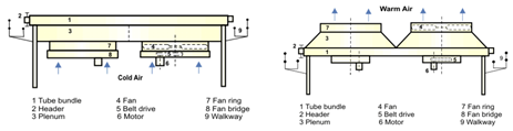
Fig. 1 Typical Forced and induced draught air cooled Heat exchanger [5]
The objective of research into air-cooled heat exchangers is improved performance and design to reduce energy usage, minimize thermal resistance, and enhance heat transfer. Researchers create smaller, more effective, and environmental-friendly heat exchangers with the new shapes of the fins being investigated and maximal airflow dynamics coupled with material choices. The other development is the creation of complex geometries and personalized designs with improvements in manufacturing processes such as additive manufacturing. Future developments in air-cooled heat exchanger technology could lead to further advancements in energy efficiency and thermal control.
Heat sinks are crucial parts of air-cooled heat exchangers, especially when it comes to cooling electronics. They effectively release the heat produced by these devices into the atmosphere. Extended surface area, high thermal conductivity materials (such as copper or aluminium), improved fin design, and appropriate airflow control affect their performance.
Using heat sinks in air-cooled heat exchangers has several advantages, such as increased thermal performance, cost-effectiveness, and compact design.[6] They are widely used in many industrial processes, automotive systems, and electronics cooling. Because of their efficient heat transfer capabilities, heat sinks are essential for preserving ideal operating temperatures and averting system breakdowns in air-cooled heat exchangers
II. REVIEW
Seri Lee at el [7] The research on air-cooled heat exchangers has been extensive, focusing on various aspects of design, optimization, and performance analysis. Researchers have developed analytical and numerical models to predict heat sink behavior, conducted parametric studies to identify optimal design parameters, and validated their findings through experiments. Novel design concepts, such as innovative fin geometries and the integration with other cooling technologies, have also been explored. This research has led to significant advancements in the field, including the development of more efficient heat exchangers and a better understanding of their performance under different conditions. However, further research is needed to address remaining challenges and explore emerging opportunities, such as uncertainty quantification, transient analysis, and integration with emerging technologies.
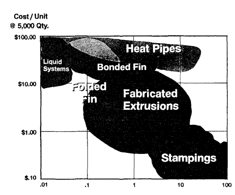
Fig. 2 Cost versus Required Thermal Resistance
Ali Elghool at el [8]. This paper provides a comprehensive review of the classification of heat sinks and their applications TEG systems. It discusses the principles and theories behind TEG technology, the materials used in TEG devices, and the factors affecting their conversion efficiency. Additionally, the paper delves into the different types of heat sinks and their role in optimizing TEG performance. Overall, the research on TEGs has shown promising results, and with continued advancements in materials and design, TEGs have the potential to play a significant role in meeting future energy demands while reducing our reliance on fossil fuels.
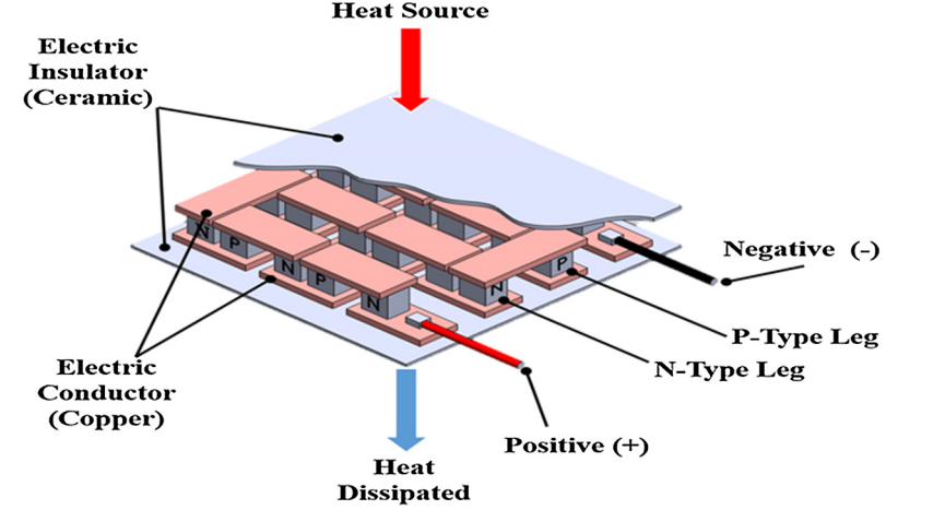
Fig. 3 Practical TEG when P-N junctions connect in series to increase operating voltage
Jonathan et al [9]. High-aspect-ratio heat sinks are innovative cooling solutions designed to enhance thermal management in compact systems. By incorporating tall, slender fins relative to their base thickness, these heat sinks significantly increase surface area for heat dissipation without requiring substantial space. Allison’s research demonstrates the effectiveness of such designs, highlighting a convection thermal resistance as low as 0.43K/W and achieving this with a modest pumping power of 0.72W. This balance between efficiency and energy consumption is critical for modern electronics where both performance and energy savings are priorities. Through a combination of theoretical analysis, computational modeling, and experimental validation, the study establishes key scaling laws, enabling the design of tailored solutions for various applications. These findings underscore the scalability and practicality of high-aspect-ratio heat sinks for next-generation thermal management systems.
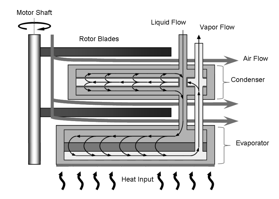
Fig. 4 Cross sectional area of the PHUMP design.
Yoong Hoon Lee’s et al [10]. Showed study on air-cooled heat sinks emphasizes their critical role in managing the thermal demands of high-performance electronics. The research highlights key aspects, including fin design, material properties, and airflow mechanisms, that significantly influence the efficiency of these cooling systems. By optimizing fin geometry and using high-conductivity materials like aluminum and copper, the study demonstrates a reduction in thermal resistance, ensuring effective heat dissipation. Additionally, the comparison between natural and forced convection reveals the advantages of enhanced airflow for high-power applications, despite the added energy costs of fans. The findings underscore the scalability and adaptability of air-cooled heat sinks, making them suitable for diverse applications, from consumer electronics to industrial systems. This work provides valuable insights for designing reliable, efficient, and cost-effective cooling solutions, addressing the growing need for advanced thermal management in modern technologies.
Totani Yuki et al [11]. Showed research on heat-exchanger heat sinks presents a groundbreaking approach to thermal management by integrating the efficiency of heat exchangers with the simplicity of heat sinks. The study emphasizes the use of advanced fin structures and thermally conductive materials, such as aluminum and copper, to maximize heat transfer and ensure rapid dissipation. By incorporating fluid flow dynamics, the system effectively leverages both conduction and convection to achieve superior thermal performance.
Key benefits, such as reduced thermal resistance, compact design, and adaptability for various applications, make this innovation particularly suited for industries like automotive systems, HVAC, and electronic cooling. The combination of experimental analysis and numerical simulations in the study validates its effectiveness, highlighting its potential as a scalable and energy-efficient solution to meet the growing thermal challenges of modern technologies.
Ambarish Maji and Gautam Choubey’s et al [12]. A review on the improvement of heat transfer through fins offers a comprehensive analysis of recent innovations in fin design, materials, and cooling techniques. The study emphasizes how advancements in fin geometry—such as modified shapes and variable profiles—along with the use of high thermal conductivity materials, significantly enhance heat dissipation in thermal management systems. Additionally, the review highlights the growing importance of active and hybrid cooling systems, integrating both passive and active methods to improve thermal performance. These developments are particularly relevant in industries like electronics cooling, automotive, aerospace, and renewable energy. The authors suggest that future research could focus on the integration of smart materials and advanced manufacturing methods to further optimize fin performance, offering new possibilities for efficient and sustainable thermal solutions.
III. ANALYSIS
Air-cooled heat sinks are for dissipating heat generated, ensuring optimal performance and longevity. Effective thermal management requires careful consideration of design parameters and analysis techniques. Key design factors include heat dissipation requirements, thermal resistance, material selection, and fin geometry. By employing computational fluid dynamics (CFD) simulations and experimental testing, engineers can analyse temperature distribution and heat transfer mechanisms. This iterative design and analysis process enables the development of highly efficient heat sinks that meet specific thermal requirements, minimizing pressure drop and maximizing heat dissipation.
A. Experimental setup
The Experimental Setup section is one of the most important sections of a research paper, describing how the experiment was conducted. It should clearly indicate what materials, equipment, and procedures were used to achieve reproducibility. More importantly, this section should include experimental design, such as independent and dependent variables, control variables, and sample size. There should be a clear description of the methods of data collection and analysis: direct and indirect measurement methods, statistical techniques, and data visualization.
B. Experimental procedure
A well-structured experimental procedure holds much in performing scientific research that is rigorous and reproducible. It should involve detailed step-by-step procedures with a comprehensive list of materials and equipment, all kind of safety concerns, data collection methods, and analytical techniques. Thus, in as much as using clear and precise language, researchers can ensure that experiments are carried out precisely and efficiently following a logical sequence. Additionally, pointing to potential sources of error and discussing control variables can minimize variability and ensure greater reliability in the results.
A two 10x10 cm ,model for comprehensive heat and fluid dissipation can be understood. A comparative analysis becomes important where all key parameters include temperature distribution, fluid flow pattern, and heat transfer mechanisms, which determine the model's thermal and fluid performance. Comparisons can be made of the structural arrangements concerning dissipated heat and fluid flow through such techniques as direct comparison, performance metric evaluation, and sensitivity analysis. Thus, all the factors should be taken into account, including mesh quality, boundary conditions, material properties, and turbulence modelling, to get the proper results from the simulation. Through careful analysis and interpretation of the factors, you may aptly make decisions about the ideal design for your application.
Model dimensions:
The overall height and length of the model is 10x10 cm.
With a base height of 1cm
Sink height of 9 cm
Sink thickness of 5mm
C. Computational modelling
The process begins with creating detailed 3D CAD models that accurately represent the heat sink's geometry, dimensions, and material properties. Careful attention is paid to features like fins, base, and mounting holes, as these elements significantly impact thermal performance. Based on these insights, design modifications can be made to improve heat dissipation, reduce pressure drop, and enhance overall efficiency.
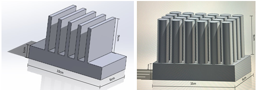
Fig. 5 CAD modelling
Through iterative CFD simulations and design optimization, engineers can develop highly efficient air-cooled heat sinks that meet the specific thermal requirements of electronic devices, ensuring optimal performance and reliability.
IV. RESULTS AND DISCUSSION
This section contains the results and also way these are more efficient , which reveal information on the thermal performance of the models under various conditions of material and heat flux/temperature. These can be compared based on temperature distributions, heat flux patterns, as well as thermal stresses, whereby several materials and loading scenarios could be evaluated as adequate for heat dissipation.
Analysis can help identify the perfect material choices and design changes to improve the thermal performance of heat sinks or electronic components and also the path or fluid through specific geometry.
As part of comparing rectangular to circular geometries of fins within the aspect of air cooling on heat exchangers, such differences in surface areas are of significance because they give difference in airflow behavior around both shapes and also differing differences of efficiency in heat transfers between rectangular fins to those with circular geometry due to large flat surface of rectangle. However, they tend to stagnate airflow at sharp corners, increase resistance, and decrease efficiency toward the tips. In contrast, round fins have an aerodynamic design that promotes smooth airflow and uniform cooling, thereby reducing stagnation zones and improving performance, especially in high-speed air movement scenarios. Although the circular fins have lower surface area as compared to rectangular fins, its streamlined geometrical shape optimizes the air flow utilization, so it becomes suitable for compact and forced convection systems. Eventually, the choice among these geometries depends upon balancing needs of heat transfer, the dynamics of airflow, and the spatial constraints to achieve optimal performance in a heat exchanger.
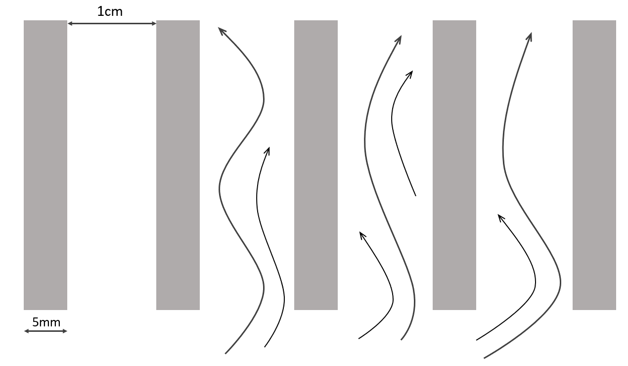
Fig. 6 Fluid flow for rectangular fin
A rectangular fin is designed to enhance heat dissipation by increasing the surface area available for heat transfer, utilizing conduction, convection, and sometimes radiation. Heat flows from the base of the fin through conduction and dissipates into the surrounding air or fluid via convection, with radiation playing a minor role in low-temperature applications. The top and bottom parts of the fin are two flat surfaces, which provide primary heat dissipation area from the large surface area involved with the surrounding medium. The edges add to more surface area for heat transfer, especially in forced convection applications where the airflow further increases their effectiveness. Although the fin tip is less effective, it can be optimized by features such as grooves to enhance residual heat dissipation. The heat dissipation performance is affected by material thermal conductivity, fin geometry, thickness, aspect ratio, and ambient conditions. Surface area can be increased by perforations, the fin spacing optimized for airflow, and high-conductivity materials selected. Emissive coatings may also be applied and enough airflow ensured. For instance, in heat sinks, the flat surfaces are meant to dissipate most of the heat, while edges and tips add to its efficiency, especially in the forced convection setup. Optimizing these features will help rectangular fins achieve higher heat dissipation efficiency, thus ensuring better thermal management in applications.
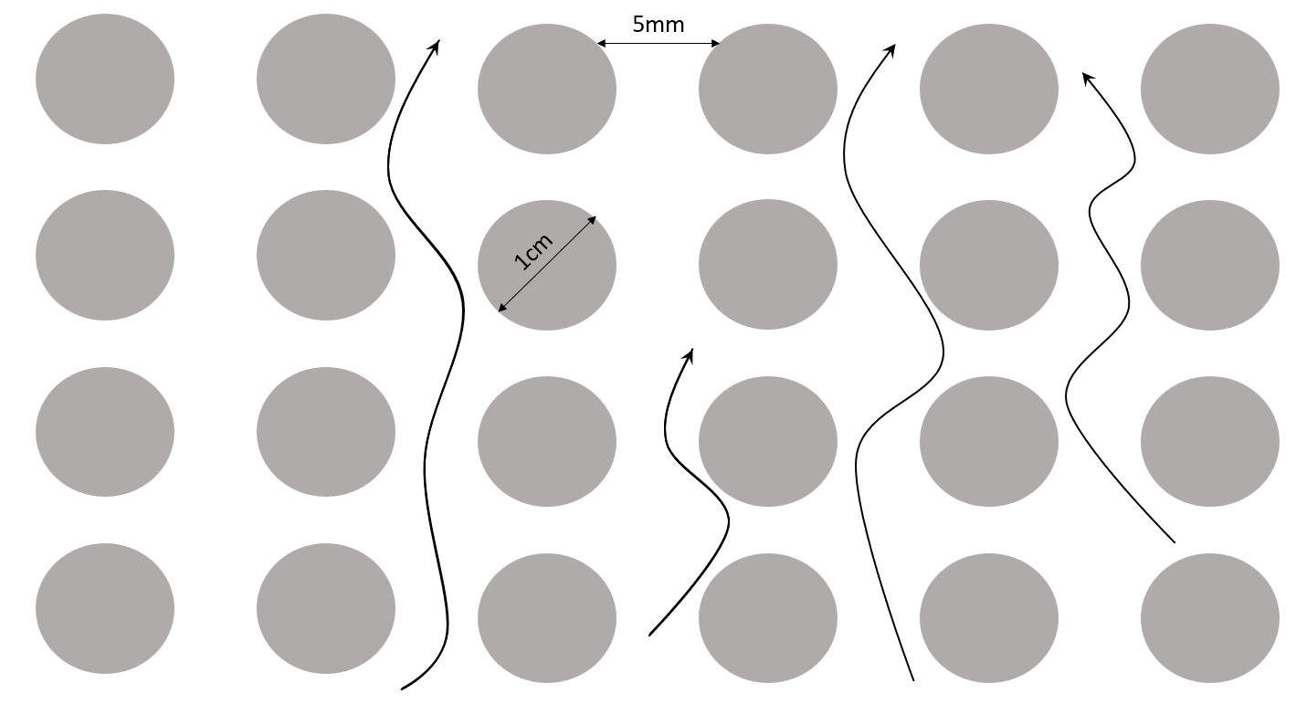
Fig. 7 Fluid flow for circular fin
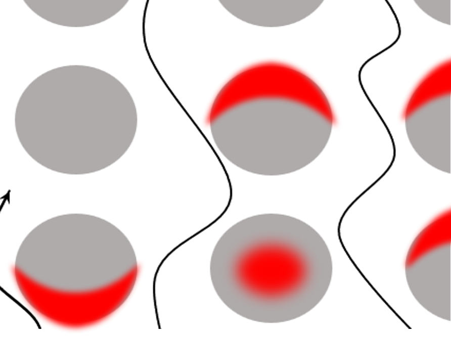
Fig. 8 area of circular fin not in use
In circular fin geometry, while the design is aerodynamic and allows for smooth air passage, most of the material, especially in the center part, does not effectively dissipate heat. The main reason for this is the inefficiency in transferring heat since the effectiveness is usually proportional to the temperature gradient between the fin surface and the surrounding medium; that decreases with distance from the fin base. This region of the inner core within the circular fins is rather insulated and less exposed to the cooling medium, hence leading to a limited convective heat transfer.
The major share of heat dissipation would be at the outer edge and the surface area of the fin that is facing the airflow. The inner part of the fin in the middle, especially surrounding the mounting or connection point, only conducts heat rather than effectively letting it dissipate. Since the outer circumference is more exposed to the surrounding airflow, it plays a more active role in cooling by transferring heat via convection. However, the unused central area adds to the material cost and weight of the fin without significantly improving performance, making it less material-efficient compared to other geometries.
In contrast, the material can be used better with the designs of rectangular or segmented fins as more of the surface is exposed to direct airflow so that the heat dissipation is distributed well all along the fin. These kinds of inefficiencies with circular fins can be addressed with perforations, hollow sections, or optimization in the material distribution so that unused core area is minimized for improvement in both performance and material usage.
A. Copper
The study involves analyzing the behavior of copper under varying material properties, temperature, and heat flux using two distinct models, potentially numerical, analytical, or experimental. A detailed understanding of these models is crucial, as each likely employs different assumptions, methodologies, or boundary conditions to evaluate thermal behavior. For copper, specific material properties such as purity, density, thermal conductivity, and specific heat capacity play the most important role in deciding how it responds to the thermal stimuli. Differences could be due to variations in the manufacturing process, microstructural composition, or environmental conditions. The other important factor is the range of temperature under investigation since copper has temperature-dependent thermal conductivity and might exhibit a deviation in linearity at extreme temperatures, which could affect the results. Likewise, the range or the magnitude of heat flux applied across the copper surface might play a significant role in altering the thermal gradients and overall heat transfer characteristics observed. The results obtained from both models could contain detailed measurements, including temperature profiles, heat flux distribution, changes in thermal conductivity, and material response to stress, thus enabling better understanding of the consistency and reliability of each approach. If raw data, comparative analysis, or graphical representations are available, they can lead to a better understanding of the results, especially as to how much they may deviate or correlate between the two models and the predictive accuracy of the former.
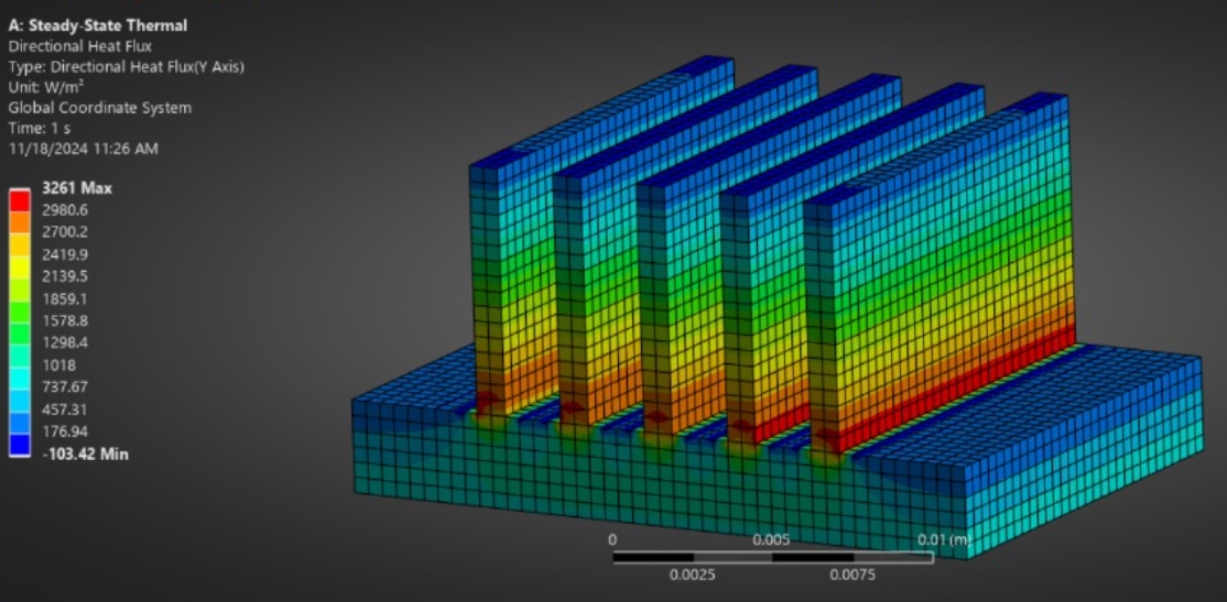
Fig. 9 Directional heat flux(rectangular)
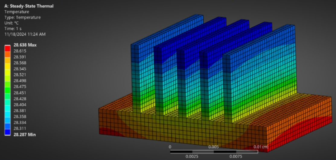 Fig.10 Temperature(rectangular)
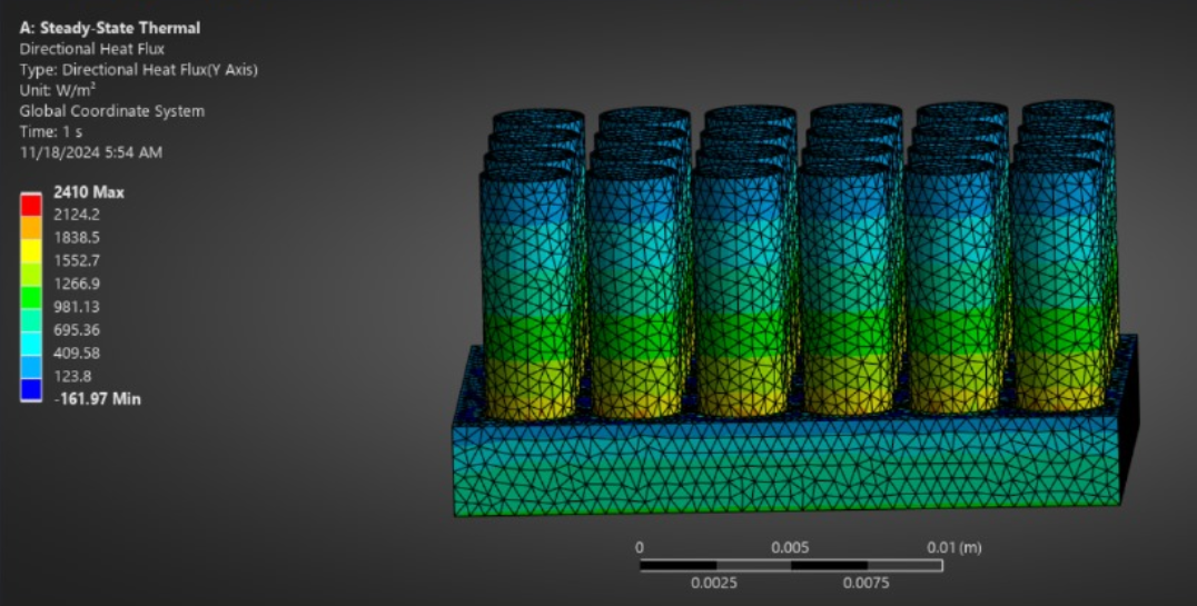
Fig. 11 Directional heat flux(cylindrical)
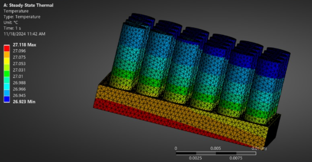
Fig. 12 Temperature(cylindrical)
B. Aluminium
The study involves analyzing the behavior of Aluminium under varying temperature, and heat flux using two distinct models, potentially numerical, analytical, or experimental. A detailed understanding of these models is crucial, as each likely employs different assumptions, methodologies, or boundary conditions to evaluate thermal behavior. For copper, specific material properties such as purity, density, thermal conductivity, and specific heat capacity play the most important role in deciding how it responds to the thermal stimuli. Differences could be due to variations in the manufacturing process, microstructural composition, or environmental conditions. The other important factor is the range of temperature under investigation since copper has temperature-dependent thermal conductivity and might exhibit a deviation in linearity at extreme temperatures, which could affect the results. Likewise, the range or the magnitude of heat flux applied across the copper surface might play a significant role in altering the thermal gradients and overall heat transfer characteristics observed. The results obtained from both models could contain detailed measurements, including temperature profiles, heat flux distribution, changes in thermal conductivity, and material response to stress, thus enabling better understanding of the consistency and reliability of each approach. If raw data, comparative analysis, or graphical representations are available, they can lead to a better understanding of the results, especially as to how much they may deviate or correlate between the two models and the predictive accuracy of the former.
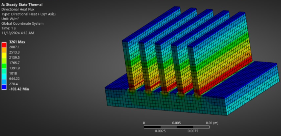
Fig. 13 Directional Heta Flux(rectangular)
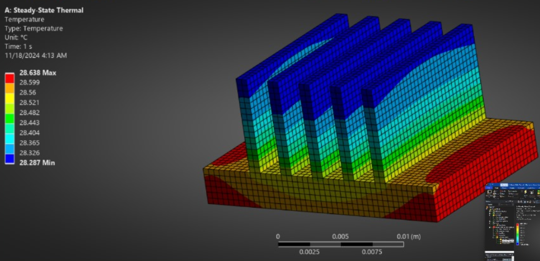
Fig. 14 Temperature(rectangular)
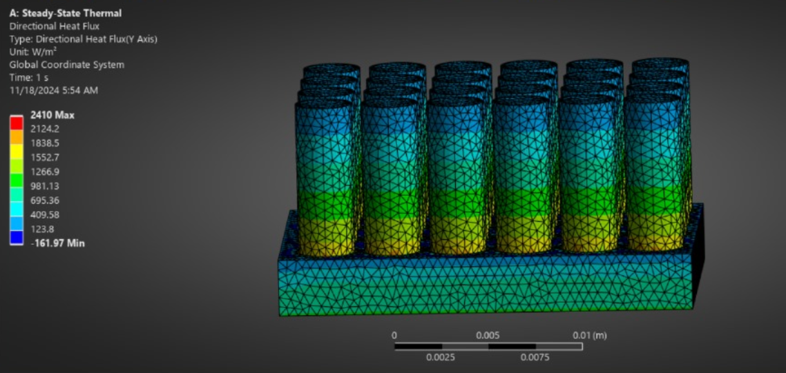
Fig. 15 Directional Heat Flux(cylindrical)
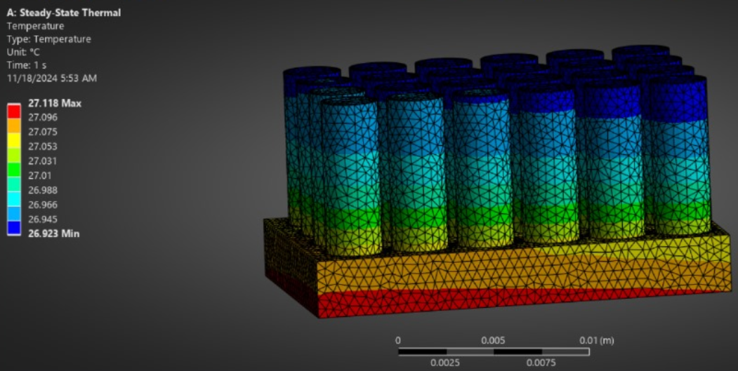
Fig. 16 Temperature(cylindrical)
Conclusion
The analysis points to super-performance air-cooled heat exchangers with material input of copper and rectangular geometries of the fin showing perfect thermal resistance and efficient dissipative performance. This further serves to enhance system reliability with improved operating efficiency along with a high standard to serve as a benchmarking entity for thermal management solutions. As manufacturing and design continue innovating towards ever greater strides, these exchangers would remain important solutions to challenges in thermal complexities that cut through industries while driving energy efficiencies and sustainability into modern systems.vital. Using knowledge of basic principles involved in transferring heat and exploring novel technologies, researchers and engineers can develop novel ACHEs that meet the needs of even the most vibrant industries.
References
[1] Metz C, Metz C. Who invented the heat exchanger? | Sterling TT. Sterling Thermal Technology. Published November 8, 2022. Accessed November 21, 2024. [2] Ni’mah, K. P., Fitriah, F., Sari, D. A. (2023). Performance of an Air-Cooled Heat Exchanger in a Separation Unit Based on Fouling Factor and Pressure Drop. Reka Buana : Jurnal Ilmiah Teknik Sipil dan Teknik Kimia, 8(2), 128-139. doi:https://doi.org/10.33366/rekabuana.v8i2.4951 [3] A. K. Dey, “Air Cooled Heat Exchangers (ACHE),” What is Piping, Oct. 23, 2019. https://whatispiping.com/air-cooled-heat-exchangers/ (accessed Nov. 21, 2024). [4] Stewart MI. Heat Transfer Theory. Elsevier eBooks. Published online January 1, 2014:39-97. doi:https://doi.org/10.1016/b978-0-12-382207-9.00003-2. [5] Summers CJ. AIR COOLED HEAT EXCHANGERS. Begellhouse eBooks. Published online August 4, 2008. doi:https://doi.org/10.1615/ [6] X.C. Tong, Advanced Materials for Thermal Management of Electronic Packaging, Springer Series in Advanced Microelectronics 30, DOI 10.1007/978-1-4419-7759-5_9, # Springer ScienceþBusiness Media, LLC 2011 [7] Seri Lee. OPTIMUM DESIGN AND SELECTION OF HEAT SINKS. Aavid Engineering Inc. Laconia, New Hampshire 03247. [8] Ali Elghool . A review on heat sink for thermo-electric power generation: Classifications and parameters affecting performance, Energy Conversion and Management, Volume 134, 2017, Pages 260 277, ISSN 0196-8904, https://doi.org/10.1016/j.enconman.2016.12.046. [9] Jonathan, Michak, Allison. (2010). Air Flow in a high aspect ratio heat sink. [10] Yoong Hoon Lee. Air cool type heat sink. SciSpace - Paper. Published September 17, 2012. Accessed November 28, 2024. [11] Totani Yuki,Hata Tetsuro,Yagita Yasuhiro,Shoutsubo Kazuyoshi. Heat-exchanger heat sink and heat exchanger provided with the heat sink. SciSpace - Paper. Published July 27, 2017. Accessed November 28, 2024. [12] Ambarish Maji, Gautam Choubey. Improvement of heat transfer through fins: A brief review of recent developments. Heat Transfer. https://doi.org/10.1002/htj.21684 [13] Gongnan Xie, Xueting Liu, Hongbin Yan, Jiang Qin. Turbulent flow characteristics and heat transfer enhancement in a square channel with various crescent ribs on one wall. International Journal of Heat and Mass Transfer, Volume 115, Part A,2017, Pages 283-295,ISSN 0017-9310, https://doi.org/10.1016/j.ijheatmasstransfer.2017.07.012. [14] Saroj Yadav, Krishna M. Pandey. A Comparative Thermal Analysis of Pin Fins for Improved Heat Transfer in Forced Convection. Materials Today: Proceedings. Volume 5, Issue 1, Part 1, 2018, Pages 1711-1717, ISSN 2214-7853, https://doi.org/10.1016/j.matpr.2017.11.268.
Copyright
Copyright © 2024 Sunil Shinde, Kripa Naik, Bhagyesh Mahajan, Parag Bonde, Adithya Krishna, Toshvi Patade, Atharv Kadam. This is an open access article distributed under the Creative Commons Attribution License, which permits unrestricted use, distribution, and reproduction in any medium, provided the original work is properly cited.

Download Paper
Paper Id : IJRASET65659
Publish Date : 2024-11-29
ISSN : 2321-9653
Publisher Name : IJRASET
DOI Link : Click Here
 Submit Paper Online