

Ijraset Journal For Research in Applied Science and Engineering Technology
Analysis of IEEE 33, 34 and 69 Bus Systems using Gauss Seidel
Authors: V Rangavalli, Komma Lavanya, D. Sri Lakshmi
DOI Link: https://doi.org/10.22214/ijraset.2022.44764
Certificate: View Certificate
Abstract
Optimum power flow studies to minimize either the power distribution losses or the cost of power drawn from the substation, without affecting on the voltage regulation. This paper discusses the concept of Gauss Seidel method to be used with load flow analysis control for stability of large power systems. Voltage Stability has become an important issue of power system stability. This paper work concentrates on simple and efficient load flow analysis of radial distribution system for finding voltage magnitudes and also the voltage profile. This load flow study of radial distribution system network is of prime importance for effective planning of load transfers. Power companies are interested in finding the most efficient configuration for minimization of real power losses and load balancing among distribution feeders to save energy and enhance the overall performance of the distribution system. This test has been performed on the 33, 34 and 69 bus systems with the use of MATLAB software.
Introduction
I. INTRODUCTION
In general, power systems are designed to work with unidirectional power flow due to the lack of power source, except for the main generating power plants. In the meanwhile, the introduction of distributed generation has changed the fundamental way of the operation in the power system distribution network from passive to active network. Distributed generation can effectively function in the distribution system in order to give additional support to the main grid by satisfying load demand, enhancing voltage profile, improving reliability and reducing power losses .The reduction of power losses is very important to maintain the efficiency of the distribution system. There are several approaches to overcome the power losses problems such as network reconfiguration as well as capacitor installation. However, the benefits of these approaches can be achieved if they are carefully coordinated in the distribution system.
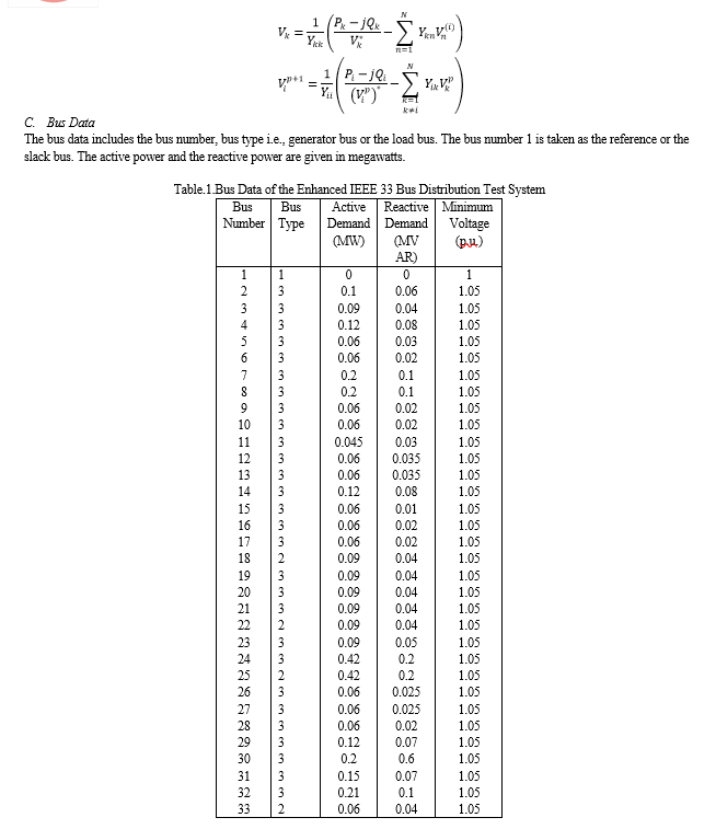
Load flow studies are important in planning and designing future expansion of power systems. The study gives steady state solutions of the voltages at all the buses, for a particular load condition. Different steady state solutions can be obtained, for different operating conditions, to help in planning, designing and the operation of the power system. Generally, load flow studies are limited to the transmission system, which involves bulk power transmission. The load at the buses is assumed to be known. Load flow studies throw light on some of the important aspects of the system operation, such as: violation of voltage magnitudes at the buses, overloading of lines, overloading of generators, stability margin reduction, indicated by power angle differences between buses linked by a line, effect of contingencies like line voltages, emergency shutdown of generators, etc. Load flow studies are required for deciding the economic operation of the power system. They are also required in transient stability studies. Hence, load flow studies play a vital role in power system studies. Thus, the load flow problem consists of finding the power flows (real and reactive) and voltages of a network for given bus conditions. At each bus, there are four quantities of interest to be known for further analysis: the real and reactive power, the voltage magnitude and its phase angle. Because of the nonlinearity of the algebraic equations, describing the given power system, their solutions are obviously, based on the iterative methods only. The constraints placed on the load flow solutions could be based on the selection of various parameters such as initial values, acceleration factor, etc. The buses are classified into different types based on the specifies and the unspecified variables at a given bus, they are Slack bus, Generator bus and the Load bus.
Slack bus also called as the swing or reference bus, in which a power system absorbs or emit the active or reactive power from the power system. The slack bus does not carry any load. At this bus, the magnitude and phase angle of the voltage are specified. The phase angle of the voltage is usually set equal to zero. The active and reactive power of this bus is usually determined through the solution of equations. Generator bus is also called the P-V bus, and on this bus, the voltage magnitude corresponding to generate voltage and true or active power P corresponding to its rating are specified. Voltage magnitude is maintained constant at a specified value by injection of reactive power. The reactive power generation Q and phase angle δ of the voltage are to be computed. It is the also called as the voltage controlled bus.
Load bus is also called the P-Q bus and at this bus, the active and reactive power is injected into the network. Magnitude and phase angle of the voltage are to be computed. Here the active power P and reactive power Q are specified, and the load bus voltage can be permitted within a tolerable value, i.e., 5 %. The phase angle of the voltage, i.e. is not very important for the load.
The slack or swing bus is usually a PV-bus with the largest capacity generator of the given system connected to it. The generator at the swing bus supplies the power difference between the "specified power into the system at the other buses" and the "total system output plus losses". Thus swing bus is needed to supply the additional real and reactive power to meet the losses. Both the magnitude and phase angle of voltage are specified at the swing bus, or otherwise, they are assumed to be equal to 1.0 p.u. and 00, as per flat-start procedure of iterative solutions. The real and reactive powers at the swing bus are found by the computer routine as part of the load flow solution process. It is to be noted that the source at the swing bus is a perfect one, called the swing machine, or slack machine. It is voltage regulated, i.e., the magnitude of voltage fixed. The phase angle is the system reference phase and hence is fixed. The generator at the awing bus has a torque angle and excitation which vary or swing as the demand changes. This variation is such as to produce fixed voltage.
II. LOAD FLOW ANALYSIS
A. Introduction
Load flow analysis is the most important and essential approach to investigating problems in power system operating and planning. Based on a specified generating state and transmission network structure, load flow analysis solves the steady operation state with node voltages and branch power flow in the power system. Load flow analysis can provide a balanced steady operation state of the power system, without considering system transient processes. Hence, the mathematic model of load flow problem is a nonlinear algebraic equation system without differential equations.
The definition of a load flow study, or power flow studies, is a numerical analysis of the flow of electric power in any electrical system. A load flow study is also an assessment of the steady-state conditions of the electrical system. Its goal is to determine the flow of power, current, voltage, real power and reactive power in a system under any load conditions. During the design phase of a new project or when evaluating changes and additions to existing electrical system, a load flow study is necessary to ensure system voltages and current remain within safe limits and whether additional equipment or services will be required. The load flow study is one of the most difficult studies in the power systems studies. This study evaluates the ability of the system to adequately supply loads while remaining within required voltage and current ranges. The power flow study report will determine voltage and power factor across all buses, as well as current or power flow across all feeders.
B. Things to remember before load flow
- Load flow study is the steady state analysis of power system network.
- Load flow study determines the operating state of the system for a given loading.
- Load flow solves a set of simultaneous non-linear algebraic power equations for the two unknown variables (|V| and ∠δ) at each node in a system.
- To solve non-linear algebraic equations, it is important to have fast, efficient and accurate numerical algorithms.
- The output of the load flow analysis is the voltage and phase angle, real and reactive power (both sides in each line), line losses and slack bus power.
C. Load flow steps
The study of load flow involves the following three steps:
- Modeling of power system components and network.
- Development of load flow equations.
- Solving the load flow equations using numerical techniques.
D. Methods in Load Flow Analysis
There are three methods for calculating the power systems data:
- Gauss-Seidel System is one of the most common types of analysis. The advantages of this system are its simplicity in operation, limited computational power required, and less time to complete. It takes less computational time per iteration. The only disadvantage here is that the number of iterations with the increase in the number of buses.
- Newton–Raphson method is a more sophisticated method, using the quadratic convergence, and can be used for more complex situations. This method takes fewer iterations to reach convergence, and therefore also takes less computer time. It also is more accurate since it is less sensitive to complicating factors such as slack bus selection or regulation transformers. One disadvantage is that programming can be complicated and requires a large computer memory.
- Fast decoupled load flow method is that it uses less computer memory. The speed of calculation is 5x faster than the Newton–Raphson method, making it a popular choice for real-time management of power grids. However, it can be less accurate since assumptions are used to obtain fast calculations. Since it is more difficult to change this computer program to look for other problems such as power system security or flow, its scope is limited.
???????E. Ways to perform Load flow analysis
There are two ways to perform load flow studies
- Mathematical Analysis
- Software Analysis
There are number of steps to be done while mathematically analyse the load flow. They are
- Step -1 – Represent the system by its single-line diagram.
- Step 2 – Convert all quantities to per unit
- Step 3 – Draw the impedance diagram.
- Step 4 – Obtain the Ybus matrix.
- Step 5 – Classify the buses (swing bus, or generator bus, or load buses)
- Step 6 – Start answering the missing variables, by assumptions (unless it is specified otherwise).
- Step 7 – Find approximations for the real and reactive power that we are given, using the assumed and given values for voltage/angles/admittance.
- Step 8 – Write the Jacobian Matrix for the first iteration of the Gauss Seidel Method.
- Step 9 – Solve for the unknown differences, use Crammers Rule.
- Step 10 – Repeat step 7 – 9 iteratively until we obtain an accurate value.
???????F. Software Analysis
Power system analysis software is an excellent tool for studying power systems, but should not be used as a substitute for knowledge and experience. There are much software that are available to help to analyse the load flow, such as ETAP, SKM, MATLAB, PSS, Neplan, and the others. Using software simplifies the carrying out of a load flow study.? However, the selection of input data required, level of detail to model, verification and interpretation of the output and utilising this to achieve the required design still requires the input of a skilled electrical engineer. Software is utilized in most of the realistic or real-time conditions since they are easier.? In doing this, the electrical engineer builds a network of nodes?interconnected by admittances (impedances).
III. IMPORTANCE OF LOAD FLOW ANALYSIS
Power flow studies are very helpful when making future plans by considering and analyzing various hypothetical situations related to electricity. For example, if the transmission line is to be removed from the system for maintenance, is the remaining line capable of serving the load without exceeding its rated value? A load flow study will answer this.
Power flow studies are performed to determine voltages, active and reactive power etc. at various points in the network for different operating conditions subject to the constraints on generator capacities and specified net interchange between operating systems and several other restraints. Power flow or load flow solution is essential for continuous evaluation of the performance of the power systems so that suitable control measures can be taken in case of necessity. In practice it will be required to carry out numerous power flow solutions under a variety of conditions.
Through load flow studies we can get information about the voltage level (V) and the voltage phase angle (δ) on each bus under steady-state conditions. This is important because the magnitude of the bus voltage must be maintained within a defined limit. After the bus angle and voltage level are calculated using the power flow, the magnitude and deviation of the reactive (Q) and real (P) power through each lines can be calculated. Also based on the difference between the power flow at the sending and receiving ends, the losses in a given line can also be calculated. In addition, we can also find out more and less load status. Power flow solutions are essential for continuous evaluation of power system performance so that appropriate control measures can be taken if required.
Load or power flow analysis is essential for the operation of the power system under current operating conditions, up-grading and future capacity expansion. The load flow studies also help us in determination of the best location as well as optimal capacity of the proposed generating stations, substations and new lines. Thus load flow studies are very important for planning existing system as well as its future expansion.
IV. GAUSS SEIDEL METHOD
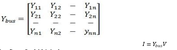
A. Bus Admittance Matrix
Bus admittance matrix is often used in power system studies. In most of power system studies it is necessary to form Y-bus matrix of the system by considering certain power system parameters depending upon the type of analysis. For example in load flow analysis it is necessary to form Y-bus matrix without taking into account the generator impedance and load impedance. In short circuit analysis the generator transient reactance and transformer impedance taken in account, in addition to line data. Y-bus may be computed by inspection method only if there is no natural coupling between the lines. Shunt admittance are added to the diagonal elements corresponding to the buses at which these are connected. The off diagonal elements are unaffected. The equivalent circuit of tap changing transformer may be considered in forming[y-bus] matrix. Impedances are expressed in per unit on a common MVA base and for simplicity resistance are neglected. Since the nodal solution is based upon Kirchhoff?s current law, impedances are converted to admittances,
???????B. Gauss Seidel Method
The Gauss-Seidel (GS) method is an iterative algorithm for solving a set of non-linear algebraic equations. To start with, a solution vector is assumed, based on guidance from practical experience in a physical situation. One of the equations is then used to obtain the revised value of a particular variable by substituting in it the present values of the remaining variables. The solution vector is immediately updated in respect of this variable. The process is then repeated for all the variables thereby completing one- iteration. The Gauss-Seidel algorithm is an iterative numerical procedure which attempts to find a solution to the system of linear equations by repeatedly solving the linear system until the iteration solution is within a predetermined acceptable bound of error. It is a robust and reliable load flow method that provides convergence to extremely complex power systems. The iterative process is then repeated till the solution vector converges within prescribed accuracy. The convergence is quite sensitive to the starting values assumed' Fortunately, in a load flow study a starting vector close to the final solution can be easily identified with previous experience. To explain how the GS method is applied to obtain the load flow solution, let it be assumed that all buses other than the slack bus are PQ buses. We shall see later that the method can be easily adopted to include PV buses as well. The slack bus voltage being specified, there are (n - 1) bus voltages starting values of whose magnitudes and angles are assumed. These values are then updated through an iterative process.
D. ??????????????Branches Data
The branch data includes the branch number, the from bus and the to bus along with their resistance and reactance values in ohms.
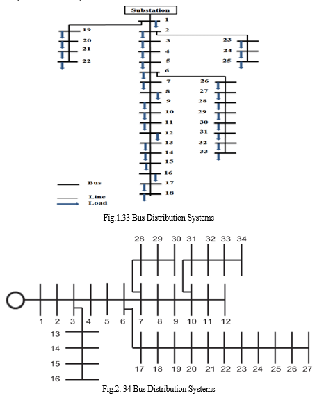
Table.2. Branch Data of the Enhanced IEEE 33 Bus Distribution Test System
|
From Bus |
To Bus |
R(Ω) |
X(Ω) |
|
1 2 3 4 5 6 7 8 9 10 11 12 13 14 15 16 17 2 19 20 21 3 23 24 6 26 27 28 29 30 31 32 |
2 3 4 5 6 7 8 9 10 11 12 13 14 15 16 17 18 19 20 21 22 23 24 25 26 27 28 29 30 31 32 33 |
0.0922 0.493 0.366 0.3811 0.819 0.1872 0.7114 1.03 1.044 0.1966 0.3744 1.468 0.5416 0.591 0.7463 1.289 0.732 0.164 1.5042 0.4095 0.7089 0.4512 0.899 0.123 0.203 0.2842 1.045 0.8042 0.5075 0.9475 0.3105 0.341 |
0.047 0.2511 0.1864 0.1941 0.707 0.6188 0.2351 0.74 0.74 0.065 0.1238 1.155 0.07129 0.562 0.545 1.721 0.574 0.1565 1.3554 1.4784 0.9373 0.3083 0.7091 0.7011 0.1023 0.1447 0.9337 0.7006 0.2585 0.963 0.3619 0.5302 |
V. OBJECTIVES AND PURPOSES OF LOAD FLOW STUDIES
The objective of load flow calculations is to determine the steady-state operating characteristics of the power system for a given load and generator real power and voltage conditions. Once we have this information, we can calculate easily real and reactive power flow in all branches together with power losses.
The other objectives of load flow studies are so that you are able to plan ahead and account for different hypothetical situations. For instance, let’s say a transmission line must be taken offline for maintenance reasons, are the lines that are remaining going to be able to handle the required loads without their rated values being exceeded.
So that load flow studies are commonly used to investigate:
- Component or circuit loading
- Bus voltage profiles (magnitude, phase angle, etc)
- Real and reactive power flow
- Power system losses
- Proper transformer tap settings
Conducting a load flow study using multiple scenarios helps to ensure that the power system is adequately designed to satisfy desired performance criteria for the most economical expenditure of initial capital investment and future operating costs.
The power flow (or load flow) studies are the essential and vital part of power system studies. Data about active and reactive power flows through the branches and the bus voltage under steady state is required by power system engineers. Power flow study provides such data. Power flow studies are extremely important and essential for power system planning, designing, expansion design and for providing guidelines to control room operating engineers (power controllers) in the following activities:
- Providing operating instructions to generating station and substation control rooms for loading, reactive power compensation relay settings, tap-setting and switching sequence. Selecting optimum settings of over-current relays.
- Analyzing the effect of rearranging the circuits on the power flows, bus voltages.
- Preparing software for online operation, control and monitoring of the power system.
- Analyzing the effect of temporary loss of generating station or transmission path on the power flow.
- Knowing the effect of reactive power compensation on bus voltages.
- Calculation of line losses for different power flow conditions.
- Evaluation of the operating performance of a power system under normal steady state.
- Planning expansion of system. Introducing HVDC line, inter-connection, EHV ac lines etc.
- Obtaining initial input data for various other power system studies such as economic load dispatch, reactive power and voltage, control, state estimation, fault calculations, generation planning, transmission planning etc.
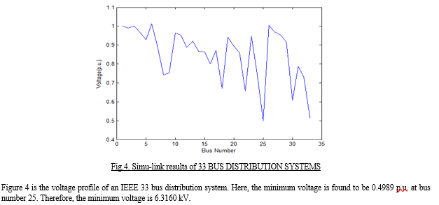
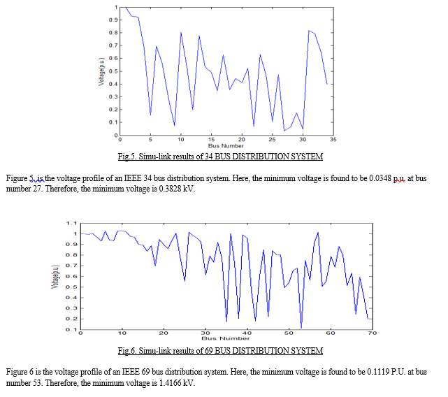
VI. RESULTS AND DISCUSSIONS
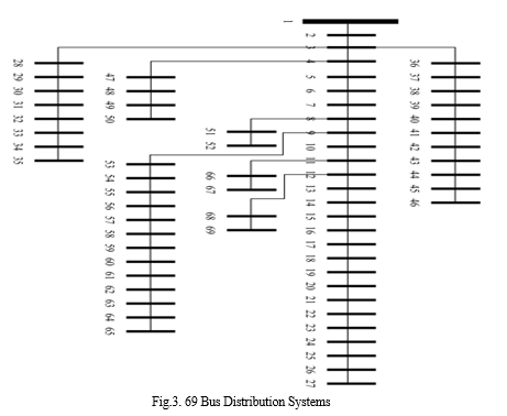
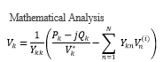
The analysis is done through the MATLAB software. The minimum voltage points are found through the voltage profiles for the 33, 34 and 69 bus system. This can be used for various distribution systems operations and planning studies that include the reconfiguration of the system. The voltage profiles of the test system at all the buses for the power flow and the optimum power flow are presented below:
 ???????
Conclusion
Load flow studies are essential for determining the operation of the excitation system. Load flow studies give us the bus voltage magnitude and phase angle of the voltage at each bus and power flow on the transmission lines and on the buses. From Gauss Seidel method, it is clear that it is used to reduce power losses by improving the voltage values in the system. We can solve the non-linear equations with simple technique. With the help of Gauss-Seidel method we can get the accurate results through iterations. We can solve the load flow equations with the Mat lab coding because it is very fast and we can get real and reactive power and voltage magnitude through some steps. The Gauss-Seidel algorithm is an iterative numerical procedure which attempts to find a solution to the system of linear equations by repeatedly solving the linear system until the iteration solution is within a predetermined acceptable bound of error. It is a robust and reliable load flow method that provides convergence to extremely complex power systems. In this paper, the case studies and numerical analyses are mainly directed on fundamental studies, such as power flow analysis.
References
[1] M. Ghorbanian, S. H. Dolatabadi, and P. Siano, “Game theory-based energy-management method considering autonomous demand response and distributed generation interactions in smart distribution systems,” IEEE Syst. J., pp. 1–10, 2020. [2] T. Tewari, A. Mohapatra, and S. Anand, “Coordinated control of oltc and energy storage for voltage regulation in distribution network with high pv penetration,” IEEE Trans. Sustain. Energy, pp. 1–1, 2020. [3] W. H. Kersting, “Radial distribution test feeders,” IEEE Trans. Power Syst., vol. 6, no. 3, pp. 975–985, Aug. 1991. [4] R. F. Arritt and R. C. Dugan, “The ieee 8500-node test feeder,” in IEEE PES T&D, Apr. 2010, pp. 1–6. [5] “Institute of electrical and electronics engineers (ieee).” [Online]. Available: https://www.ieee.org/ [6] “Ieee pes amps dsas test feeder working group.” [Online]. Available: https://site.ieee.org/pes-testfeeders/ [7] “Electric power research institute (epri).” [Online]. Available: https: //www.epri.com/ [8] “Pacific northwest national laboratory (pnnl).” [Online]. Available: https://www.pnnl.gov/ [9] “Pacific gas and electric company (pg&e).” [Online]. Available: www.pge.com [10] A. M. Stanisavljevic, V. A. Katic, B. P. Dumnic, and B. P. Popadic, “A brief overview of the distribution test grids with a distributed generation inclusion case study,” SERBIAN J. ELECTR. ENG., vol. 15, no. 1, pp. 115–129, Feb. 2018. [11] F. P. Marcos, C. M. Domingo, T. G. S. Roman, B. Palmintier, B.-M. Hodge, V. Krishnan, F. de Cuadra Garcia, and B. Mather, “A review of power distribution test feeders in the united states and the need for synthetic representative networks,” Energies, vol. 10, no. 11, pp. 1896– 1909, Nov. 2017. [12] W. H. Kersting, “Radial distribution test feeders,” in IEEE Power Eng. Society Winter Meeting. Conf. Proc. (Cat. No.01CH37194), vol. 2, Jan. 2001, pp. 908–912. [13] D. Kirschen and G. Strbac, Fundamentals of Power System Economics. John Wiley & Sons Ltd,, 2004. [14] A. J. Wood, B. F. Wollenberg, and G. B. Shebl, Power Generation, Operation, and Control. John Wiley & Sons, Inc., 2014. [15] “Ontario Power Authority.” [Online]. Available: http://www. powerauthority.on.ca/ [16] M. R. Sheibani, G. R. Yousefi, M. A. Latify, and S. H. Dolatabadi, “Energy storage system expansion planning in power systems: a review,” IET Renew. Power Gener., vol. 12, pp. 1203–1221, Aug. 2018. [17] R. D. Zimmerman, C. E. Murillo-Sanchez, and R. J. Thomas, “Mat power: Steady-state operations, planning, and analysis tools for power systems research and education,” IEEE Trans. Power Syst., vol. 26, no. 1, pp. 12–19, Feb. 2011. [18] R. D. Zimmerman and C. E. Murillo-Sanchez, “Matpower [software],” 2018. [Online]. Available: https://matpower.org [19] V. V. S. N. Murty and A. Kumar, “Reactive power compensation in ubrds based on loss sensitivity appraoch,” in 6th IEEE Power India Int. Conf. (PIICON), Dec 2014, pp. 1–5. [20] F. Ugranli, E. Karatepe, and A. H. Nielsen, “Milp approach for bilevel transmission and reactive power planning considering wind curtailment,” IEEE Trans. Power Syst., vol. 32, no. 1, pp. 652–661, Jan. 2017. [21] P. R. Gribik, W. W. Hogan, and S. L. Pope, “Market-clearing electricity prices and energy uplift,” 2007. [Online]. Available: http://www.hks. harvard.edu/fs/whogan/Gribik Hogan Pope Price Uplift 123107.pdf [22] R. Rockafellar, “Convex analysis,” 1997. [23] D. A. Schiro, T. Zheng, F. Zhao, and E. Litvinov, “Convex hull pricing in electricity markets: Formulation, analysis, and implementation challenges,” IEEE Trans. Power Syst., vol. 31, no. 5, pp. 4068–4075, Sep. 2016. [24] B. Hua and R. Baldick, “A convex primal formulation for convex hull pricing,” IEEE Trans. Power Syst., vol. 32, no. 5, pp. 3814–3823, Sep. 2017. [25] P. Denholm and M. Hand, “Grid flexibility and storage required to achieve very high penetration of variable renewable electricity,” Energy Policy, vol. 39, no. 3, pp. 1817 – 1830, 2011. [26] W. N. Chang, C. M. Chang, and S. K. Yen, “Improvements in bidirec tional power-flow balancing and electric power quality of a microgrid with unbalanced distributed generators and loads by using shunt com pensators,” Energies, vol. 11, no. 3305, 2018. [27] J. Dai, Y. Tang, Y. Liu, J. Ning, Q. Wang, N. Zhu, and J. Zhao, “Optimal configuration of distributed power flow controller to enhance system loadability via mixed integer linear programming,” J. Modern Power Syst. Clean Energy, vol. 7, no. 6, pp. 1484–1494, 2019. [28] D. M. Divan, W. E. Brumsickle, R. S. Schneider, B. Kranz, R. W. Gascoigne, D. T. Bradshaw, M. R. Ingram, and I. S. Grant, “A distributed static series compensator system for realizing active power flow control on existing power lines,” IEEE Trans. Power Del., vol. 22, no. 1, pp. 642–649, 2007. [29] K. M. Rogers and T. J. Overbye, “Some applications of distributed flexible ac transmission system (d-facts) devices in power systems,” in 40th North American Power Symp., 2008, pp. 1–8. [30] P. Arboleya, C. Gonzalez-Moran, and M. Coto, “Modeling facts for power flow purposes: A common framework,” Int. J. Electrical Power & Energy Systems, vol. 63, pp. 293 – 301, 2014. [31] P. Siano and D. Sarno, “Assessing the benefits of residential demand response in a real time distribution energy market,” Applied Energy, vol. 161, pp. 533 – 551, 2016.
Copyright
Copyright © 2022 V Rangavalli, Komma Lavanya, D. Sri Lakshmi. This is an open access article distributed under the Creative Commons Attribution License, which permits unrestricted use, distribution, andreproduction in any medium, provided the original work is properly cited.

Download Paper
Paper Id : IJRASET44764
Publish Date : 2022-06-23
ISSN : 2321-9653
Publisher Name : IJRASET
DOI Link : Click Here
 Submit Paper Online