

Ijraset Journal For Research in Applied Science and Engineering Technology
Assessment of P-Delta Effect in Multistorey Building
Authors: Prof. Pushkraj. R. Admile, Akshay. R. Jagtap, Samir. D. Gaikwad, Abhay. A. Kale, Mahesh. R. Kamble
DOI Link: https://doi.org/10.22214/ijraset.2023.53561
Certificate: View Certificate
Abstract
This research paper focuses on the analysis of the P-delta effect on high-rise structures, which has been the subject of numerous recent studies. The P-delta effect is considered the secondary effect and is deemed more significant. It arises due to an increase in the number of stories in a structure and is particularly relevant when considering lateral loads such as earthquakes and wind loads. The objective of this paper is to incorporate axial load and displacement in the calculation of the P-delta effect in multi-storey buildings. The analysis involves RCC framed structures of different heights, specifically G+15, G+20, and G+25. The load combinations are determined according to IS 456:2000, and the software E-Tabs is utilized for the analysis. The earthquake load is applied to the structure based on IS-1839 (2002), and deflection curves are observed. Both models with and without the P-delta effect are examined in terms of bending moment, shear force, and displacement. The findings clearly demonstrate the necessity of considering the P-delta effect in multi-storey buildings. The analysis is conducted using the linear static method, and the results provide valuable insights into the structural behavior under different loading conditions.
Introduction
I. INTRODUCTION
The P-Delta effect is a second-order effect, wherein 'P' represents gravity or axial load, and 'Delta' represents displacement. The magnitude of the P-Delta effect is dependent on the magnitude of the axial load. With the increasing popularity and significance of high-rise structures, nonlinear analysis of the P-Delta effect has gained importance. The aim is to investigate the relationship between structural height and the P-Delta effect, which is a second-order effect.
As the number of storeys increases, there is an increased reduction in the resistance to collapse, indicating an increase in the P-Delta effect. If there is a change in moments, shear at the base, or displacement greater than 10%, it further amplifies the P-Delta effect. Additionally, the inclusion of shear walls leads to changes in the P-Delta effect.
It has been observed that the P-Delta effect increases with an increase in the slenderness ratio and the number of storeys. The P-Delta effect is prominent in buildings with a height exceeding 61 meters and without shear walls. The base shear and torsion values of buildings, with or without shear walls, are reduced due to the application of the P-Delta effect. These buildings are designed based on traditional building codes and are expected to experience inelastic actions during design-level earthquakes. The interaction between torsion and the P-Delta effect can be complex, particularly in the inelastic range of behavior. Inelastic actions can be influenced by both torsion and the P-Delta effect, with torsion playing a more significant role within the P-Delta effect. The type of lateral load resisting system employed in the structure also affects the degree to which torsion modifies the P-Delta effects. Hence, the characteristics of the lateral load resisting system hold greater importance than the number of storeys in high-rise buildings.
II. NEED OF THE PRESENT STUDY
In case of high-rise buildings, as the structure becomes more slender and less resistant to deformation, it is necessary to consider 2nd order and to be more specific, P-delta effects arises .As a result, codes of practice are referring engineers more and to the use of 2nd order analysis in order that P-delta and “stress stiffening effects are accounted for when appropriate in design. This is as true in concrete and timber design as it is in the design of steel work.
III. OBJECTIVES OF THE PRESENT STUDY
The primary objective of this work is to analyze the seismic capacity of gravity designed 10, 15, and 20 storied RC framed buildings using linear static and nonlinear static pushover analysis. It is also intended to check the above building for second order P-Delta effect are within acceptable limit or not and to show how to make a structure safe for second order P-delta effect. Detailed study of P-Delta effect.
- To study the effects of axial loadings on high rise buildings
- To Analysis of G+9, G+14 and G+19 storyR.C.C. buildings with and without considering P-Delta effects.
- Linear static Analysis procedure is carried out by using E-Tab ,for ascertaining the seismic Capacity of buildings.
- Nonlinear static pushover analysis procedure is carried out by using E-Tab for ascertaining The seismic capacity of building.
- To decide the minimum height of building for which it is necessary to included P-delta Effect in analysis.
- To calculate the % change in the values of forces ,deflections and moments considering P-delta effect and without considering P-Delta effect and without considering P-Delta effect of structures.
- To decide the minimum height of building for which it is necessary to include P-delta effect in analysis.
- To make a structure stiffer for bringing it within acceptable limit according to the code.
IV. OBJECTIVES OF THE PRESENT STUDY
V. IATC40
Seismic evaluation and retrofit of concrete buildings commonly referred to as ATC40 was developed by the Applied Technology Council (ATC) with funding from the California Safety Commission. Although the procedures recommended in this document are for concrete buildings, they are applicable to most building types. ATC40 recommends the following steps for the entire process of evaluation and retrofit:
- Initiation of a Project: Determine the primary goal and potential scope of the project.
- Selection of Qualified Professionals: Select engineering professionals with a demonstrated experience in the analysis, design and retrofit of buildings in seismically hazardous regions. Experience with PBSE and nonlinear procedures are also needed.
- Performance Objective: Choose a performance objective from the options provided for a specific level of seismic hazard.
- Review of Building Conditions: Perform a site visit and review drawings.
- Alternatives for Mitigation: Check to see if the nonlinear procedure is appropriate or relevant for the building under consideration.
- Peer Review and Approval Process: Check with building officials and consider other quality control measures appropriate to seismic evaluation and retrofit.
- Detailed Investigations: Perform a nonlinear static analysis if appropriate
- Seismic Capacity: Determine the inelastic capacity curve also known to pushover curve. Covert to capacity spectrum. Seismic hazard: obtain a site specific response spectrum for the chosen hazard level and convert to spectral ordinates format.
- Verify Performance: Obtain performance point as the intersection of the capacity spectrum and the reduced seismic demand in spectral ordinates (ADRS) format. Check all primary and secondary elements against acceptability limits based on the global performance goal..
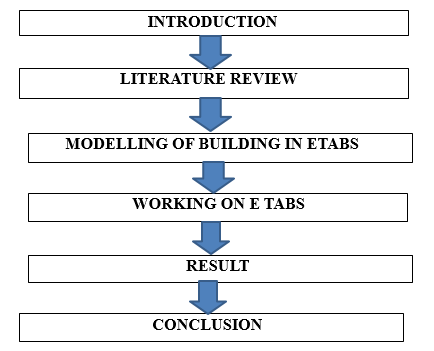
VI. WORKING ON E TAB
- There are three types of hinge properties in ETAB. They are default hinge properties, user-defined hinge properties and generated hinge properties. Only default hinge properties and user-defined hinge properties can be assigned to frame elements. When These hinge properties are assigned to a frame element, the program automatically creates a different generated hinge property for each and every hinge.
- In ETAB, a frame element is modeled as a line element having linearly elastic properties and nonlinear force-displacement characteristics of individual frame elements are modeled as hinges represented by a series of straight line segments. A generalized forcedisplacement characteristic of a non-degrading frame element (or hinge properties) in ETAB is shown in fig.
- Point A corresponds to unloaded condition and point B represents yielding of the element. The ordinate at C corresponds to nominal strength and abscissa at C corresponds to the deformation at which significant strength degradation begins. The drop from C to D represents the initial failure of the element and resistance to lateral loads beyond point C is usually unreliable. The residual resistance from D to E allows the frame elements to sustain gravity loads.
- Beyond point E, the maximum deformation capacity, gravity load can no longer be sustained. Hinges can be assigned at any number of locations (potential yielding points) along the span of the frame element as well as element ends. Uncoupled moment (M2 and M3), torsion (T), axial force (P) and shear (V2 and V3) force displacement relations can be defined. As the column axial load changes under lateral loading, there is also a coupled PM2-M3 (PMM) hinge which yields based on the interaction of axial force and bending moments at the hinge location M3 hinges for beams. Also, more than one type of hinge can be assigned at the same location of a frame element. Default hinge properties cannot be modified.
- They also cannot be viewed because the default properties are section dependent. The default properties cannot be fully defined by the program until the section that they apply to is identified. Thus to see the effect of the default properties, the default property should be assigned to a frame element, and then the resulting generated hinge property should be viewed.
- The built-in default hinge properties are typically based on FEMA356 and/or ATC40 criteria. User-defined hinge properties can be either based on default properties or they can be fully user-defined. When user-defined properties are based on default properties the hinge properties cannot be viewed because, again, the default properties are section dependent. When userdefined properties are not based on default properties, then the properties can be viewed and modified.
VII. RESULT AND DISCUSSION
A. Result of 15, 20, Storey Buildings
Graphical representation of 1% increase in deflection and B.M. values due to all load cases with and without P-delta effect:-
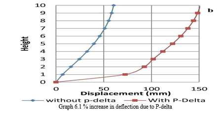
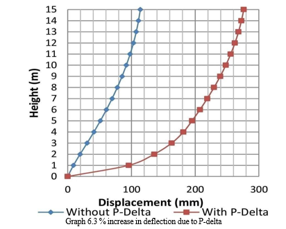
- Graph 6.1
a. Graph 6.1 represents % increase in deflection for various load cases for 15, 20 and 25 storey building.
b. From graph, it is observed that increase in deflection is more as number of storey increased.
c. Alos, P-delta effect is more observed in load cases 3, 4, 7, 8, 11, 12(the cases in which earthquake load is in y-direction). So P-delta effect is more observed in y-direction.
Graph 6.2 % increase in deflection due to P-delta
2. Graph 6.2
Graph 6.2 represents % increase in B.M. for various load cases for 15, 20 and 25 storey building.
From graph, it is observed that increase in B.M. will increase P – delta effect.
VIII. DISCUSSION
A. For 15 Storey Building
- Change in B.M. at base is 2-6%.
- Change in the deflection is 1-11%.
- Change in B.M. of beams is less than 10%.
- Change in the B.M of the columns is up to 20% for some members in some load cases. But it is found that their initial values are very small (i.e. not more than 30KNm). So we can say that practically it is not necessary to consider P-delta effect.
- Hence for 15 storey building, it is not necessary to consider P-delta effect, so building can be designed by 1st order analysis.
B. For 20 Storey Building
- Change in B.M. at base is 2-4%.
- Change in the deflection is 2-14%.
- Change in B.M of beams which are parallel to y-direction is up to 15%.
- Change in B.M of columns is 8-30%. It is more observed at the exterior columns and their nearby beams. Also it is more observed at intermediate stories.
- So P-delta effect is observed in some load cases for 20 storey building.
- So it is necessary to consider P-delta effect while designing a 20 storey building.
Conclusion
This chapter presents the major conclusions and future scope of the assessment of P-delta effect for high rise buildings. Based on the second order analysis using ETAB and verification with other authors following conclusions can be drawn. 1) As number of storey increases P-delta effect becomes more important. 2) P-delta effect is only observed in some of the beams and columns (Exterior columns and their adjacent beams) in some load cases. If these load cases are governing load cases for design of member, then only we can say that it is considerable. This condition is observed in 20 and 25 storey buildings and mostly in 25 storey building. 3) So we can say that, at least it is necessary to check the results of analysis with and without considering P-delta effect for the buildings. 4) Iterative P-delta analysis method is used. Building is by default analyzed for 10 numbers of iterations in ETAB. But the same results are observed for single iteration also. So there is no change in results by increasing the iterations. 5) Also analysis is performed by considering the seismic loading in other zones in India. Similar results are observed in the form of increase in internal forces. 6) So we should prefer form delta analysis for designing a minimum of 20 storey building considering seismic loads. And buildings up to 20 stories can be designed by conventional primary analysis or linear analysis. 7) The conclusion is valid for RCC residential buildings for seismic loading in all the zones of India and may not be applicable for commercial, educational or industrial buildings. 8) As the cross sections of members increases stiffness of a structure also increases. 9) We can bring building within permissible limit for P-delta effect by increasing the cross sections of members.
References
[1] M.A.A Mollick, “Experimental study of P-DELTA Effect In High rise building”, Journal of civil engineering , The institute of Engineers, Bangladesh, VOL.CE 25 ,No.2,1997. [2] A.S. Moghdam and A. Aziminejad, “Interaction of torsion and P-delta effect in tall buildings”,13th World conference on earthquake engineering, Vancouver, B.C., Canada, Aug1-6,paper no 799, 2009. [3] T.K. Bandyopadhyay ,D. Dattasaha , A. Choudhuri,”Effect of P-Delta analysis for slender building structures”, Institute for steel development and growth (INSDAG), “IspatNiketan ”, Kolkata,India,1999 [4] Angela M. Schimizze, “Comparison of P-delta analysis of plane frames using commercial structural analysis programs and current AISC design specifications”, Thesis submitted to the faculty of the Virginia Polytechnic Institute and state university, 2001. [5] Bulent N. Alemdar, “Modification to current P-delta implementation for rigid diaphragms”, July2010. [6] Pushkaraj Admile, “Assessment of P-Delta effect on High rise buildings” ,June 2015
Copyright
Copyright © 2023 Prof. Pushkraj. R. Admile, Akshay. R. Jagtap, Samir. D. Gaikwad, Abhay. A. Kale, Mahesh. R. Kamble. This is an open access article distributed under the Creative Commons Attribution License, which permits unrestricted use, distribution, and reproduction in any medium, provided the original work is properly cited.

Download Paper
Paper Id : IJRASET53561
Publish Date : 2023-06-01
ISSN : 2321-9653
Publisher Name : IJRASET
DOI Link : Click Here
 Submit Paper Online