

Ijraset Journal For Research in Applied Science and Engineering Technology
Automatic Workpart Transfer Mechanism
Authors: Anjali Vardai, Giridhar Agadi, Abhay Devmore, Bhimappa Hanji, Karthik Ramdurg
DOI Link: https://doi.org/10.22214/ijraset.2022.45474
Certificate: View Certificate
Abstract
The main concept behind our project is replacement of treadmill mechanism for small scale industries which is fully automated, functional, easy to use, highly accessible and easily maintainable. There is a serious demand for mechanisms for movement of packages in the industries right from the start to end. The advantage of our system over the conveyor system is that the system has a time delay between moving packages and this delay can be used to introduce any alterations in the package or move the package for any other purposes. While in conveyor system such actions cannot be performed unless programmed module is used to produce intermittent stopping of the belt which basically is costly. Here we are working to convert rotary motion into reciprocating motion by means of a single slider crank mechanism this prototype is solely based on four bar mechanism. Conventional conveyer systems consist of belts, large input/output motors etc. which increases the initial cost as well as maintenance cost. The results from this project can be used by many small-scale industries and in-house industries where conveyor system is not accessible.
Introduction
I. INTRODUCTION
There is a serious demand for intermittent movement of packages in the industries right from the start. Though the continuous movement is more or less important in the same field the sporadic motion has become essential. The objective of our project is to produce a mechanism that delivers this stop and move motion using mechanical linkage. The advantage of our system over the conveyors system is that the system has a time delay between moving packages and this delay can be used to introduce any alterations in the package or move the packages for any other purpose. While in conveyors system such actions cannot be performed unless programmed module is used to produce intermittent stopping of the belt which basically is costly. The prototype design requires electric motor, shafts and the frame and platform on which the packages can be moved is fabricating. All the links are being made of Mild steel which has a direct contact with the boxes being moved. The system is expected to move as packages as 2-3 kg’s approximately [1].
The box transport mechanism has a simple mechanism, it can be operated with a crank and links arrangement. The wiper motor rotary motion is converted into the to and fro motion of the linkages, the linear motion is obtained by conversion of rotary motion by the use of cranks and mechanical linkages. If we take the fact that same work can be done by thread mill of other mechanisms which are used in large scale industries and factories but small scale industries will not be able to afford them. In case of thread mill mechanism as it always in continues in motion so when a human involvement is introduced to it sometimes causes time delays which causes an effect on production process this problem can be solved by using box transport mechanism. So a basic module of moving packages is designed using CAD/CAM with a time delay which can be used to do alterations if required in the package or moves the package or production line [3].
This invention relates to improvements in transfer and conveyer belt devices, and it relates particularly to devices for transferring components and other items. It can be used by many small-scale industries and in-house industries where conveyor system is not accessible [3]. Conventional systems are not equipped with this stop and go motion unless they are programmed to stop at a designated stop which again increases the cost [4].
A linkage is a mechanism formed by connecting two or more levers together. Linkages can be designed to change the direction of a force or make two or more objects move at the same time. Many different fasteners are used to connect linkages together yet allow them to move freely such as pins, end-threaded bolts with nuts, and loosely fitted rivets [6].
There are two general classes
Linkages
Simple planar linkages and more complex specialized linkages; both are capable of performing tasks such as describing straight lines or curves and executing motions at differing speeds.
Linkages can be classified according to their primary functions
- Function generation: The relative motion between the links connected to the frame
- Path generation: The path of a tracer point
- Motion generation: The motion of the coupler link
II. OBJECTIVES
The aim of this project is to fabricate the Transfer mechanism which can make easier to transfer work parts/products from one place to another place while processing in the factories. To restrict (Automate) continuous movement of the mechanism by using Ultrasonic sensor. Understanding the Fabrication Techniques in a mechanical workshop.Understand the usage of various mechanical machine measuring Tools. The main purpose of the machine is to eliminate the human efforts
III. METHODOLOGY
A four bar linkage, also called a four-bar, is the simplest movable closed chain linkage. It consist of four bodies, called bar or links, connected in a loop by four joints. Generally, the joints are configured so the links move in parallel planes, and the assembly is called a planner four-bar linkage. If the linkage has four hinged joints with axes angled to intersect in a single point, then the assembly is called a spherical four-bar linkage. Bennett’s linkage is a spatial four bar linkage with hinged joints that have their axes angled in a particular way that makes the system movable [1].
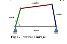
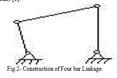
A. Construction Of Four Bar Linkages
In the range of planer mechanisms, the simplest group of lower pair mechanisms is four bar linkages. A four bar linkages comprises four bar shaped links and four turning pair as shown in constructional fig. 2. The link opposite the frame is called the coupler link, and the links which are hinged to the frame is called side links. A link which is free to rotate through 3600 with respect to a second link will be said to revolve relative to the second link (for all four bars to becomes simultaneously aligned, such a state is called a change point) [1].
B. Working Principle
Crank-Rocker Mechanism: A 4-bar linkage mechanism has a crank that rotates at a constant angular speed. The crank is connected to the coupler which is connected to the rocker. The frame does not move [5].
Grashoff’s Criteria
Before classifying four-bar linkages, we need to introduce some basic nomenclature. In a four-bar linkage, we refer to the line segment between hinges on a given link as a bar [5].
Where: s = Length of shortest bar l
l=Length of longest bar 2
p, q = lengths of intermediate bar Grashoff's theorem states that a four-bar mechanism has at least one revolving link if
s + l <= p + q (5-1)
And all three mobile links will rock if
s + l > p +q (5-2)
the inequality (5-1) is Grashoff's criterion.
All four-bar mechanisms fall into one of the four categories [5].
Table.1- Types of Crank Rocker Arrangement
|
SI. No. |
Case |
l + s varies p + q |
Shortest Bar |
Type |
|
1 |
1 |
< |
Frame |
Double-crank |
|
2 |
2 |
< |
side |
Rocker-crank |
|
3 |
3 |
> |
Coupler |
Double rocker |
|
4 |
4 |
= |
Any |
Change point |
|
5 |
5 |
> |
Any |
Double-rocker |
IV. PARTS
1Ultrasonic Sensor
2. Arduino Uno- ATmega328P
3. DC motor
4. Relay
5. Display- 16x2 LCD Interface (JHD162a – HD 44780 Compatible Display Controller)
6. Metal frame
7. Wiper motor
8. Battery 12 V
9. Nuts and bolts
10. Wires for connection
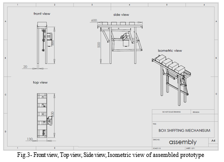
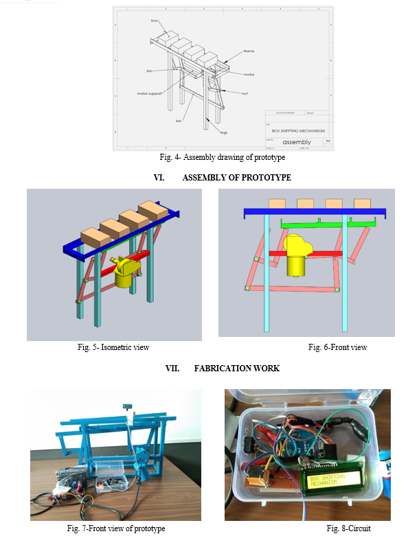
V. PROTOTYPE DESIGN AND CAD DRAWINGS
VIII. APPLICATIONS
- Pharmaceutical and Beverage Industries
- Heavy applications container lifting.
- Transferring the boxes from one place to another in the sections of assembly lines and packing lines etc in the industry.
- Wildly used in box folding or forming machine to the operator of a semi-automatic box wrapping machine
- Implementing technology of ultrasonic sensor, we can obtain the automated transfer system to switch on and off the mechanism.
IX. FUTURE SCOPE
This transfer system will ramp up the speed of production when used in small scale industries. Dynamic analysis is one of the very important Phase in design the systems. Before building a prototype, a CAD based design and simulation of working model gives a better understand regarding the rigidity of system parameter. There is a much to the scope in development of an accurate mathematical model and simulation for the kinematics, dynamics, and motion analysis of the machine for the precise application. According to us this easy and simple to use prototype design will revolutionize the concept of box transfer mechanism. As it is easy to fabricate small scale industries will be able to utilize this product for the betterment in the plant management. As transporting boxes from the assembly line will get more manageable industries could easily increase their production rate and so their revenue. Further advancements and modifications can be done as per the requirements as well as scale of the use.
Conclusion
In this project we learnt about how to prepare the box transporting machine. This box transfer mechanism plays a major role in industries, the process of transporting or shifting of products from one place to another is to be maintained by conveyors only. So we just successfully altered this with a box transfer mechanism using the kinematic links and a motor. We have just implemented our basic mechanical knowledge and designing skills for designing and fabricating this project successfully. Thus this project work will be useful in all industries. For practical application its height, weight are suitable for light duty operations. But with time and with few modifications as the prototype will demand in future, it’s efficiency and capabilities could be enhanced. The project works with satisfactory conditions. We are able to understand the difficulties in maintaining the tolerances and also quality. As the design and construction point of view, it is easy to build the entire prototype with less cost. Hence this prototype is feasible for light duty operations of small scale industries.
References
[1] Sandesh Shinde, Sachin Jaid, Akshay Jaid, Nilesh Waykar, Mr. Pawar P. S.(2016) “box transfer machine” International Journal of Engineering Sciences & Management Volume 6 Issue No 1. [2] Siva Krishna Y and Moulali S K, “Design and Fabrication of box transport mechanism “International Journal of Modern Trend in Engineering and Research Volume 6 Issue No 1, December 2017. [3] Mohd. Mohtashim Danish, Tushar S. Nitnaware, Piyush Pagar, “BOX TRANSPORT MECHANISM” International Journal of Advance Research in Science and Engineering, Volume 6 Issue No 1,January 2017. [4] Patel Bhautik ,Sharma Saharsh ,Prajapati Ankur , Patel Shweta, Sunil J Patel “development of box transfer mechanism”Volume-4 Issue-2 2018. [5] Dr. G Diwakar, G.P.S. Narendra, G S V Gopal Prakeerthi,D Mahesh Naidu, G Revanthi, “Design and Simulation of Box Transport Mechanism” International Journal of Innovative Science and Research Technology, Volume 5, Issue 11, November – 2020. [6] Ulhas Patil, Tejas Kale, Prasad Kulkarni, Parag Lokhande, Mr. Yogesh Vanjari, “Box Transport Mechanism”, International Journal of Innovations in Engineering and Science, Volume 6, No. 10, 2021.
Copyright
Copyright © 2022 Anjali Vardai, Giridhar Agadi, Abhay Devmore, Bhimappa Hanji, Karthik Ramdurg. This is an open access article distributed under the Creative Commons Attribution License, which permits unrestricted use, distribution, and reproduction in any medium, provided the original work is properly cited.

Download Paper
Paper Id : IJRASET45747
Publish Date : 2022-07-18
ISSN : 2321-9653
Publisher Name : IJRASET
DOI Link : Click Here
 Submit Paper Online