

Ijraset Journal For Research in Applied Science and Engineering Technology
CFD Analysis of Cone Shaped Coil Heat Exchanger by Using Copper Oxide Nanofluid with Ethylene Glycol and Water as Its Base Fluid in Aluminium Tube with Different Mass Flow Rate
Authors: Navneet Kumar, Vijaykant Pandey
DOI Link: https://doi.org/10.22214/ijraset.2022.47069
Certificate: View Certificate
Abstract
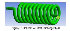
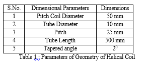
The recovery of waste heat has been a topic of concern for large-scale industrial companies for several decades. This recovery not only makes an operation more environment friendly, but it also helps to cut costs. In addition to this, it can reduce the amount of resources needed to power a facility. Many industries have implemented different methods of waste heat recovery. In this present paper the efforts are made to understand that how to compare the heat transfer rate in Cone shaped coiled tube heat exchanger using CuO Nano fluid with Water and Ethylene glycol as a base fluid in Cone shaped Heat Exchanger with the help of CFD on aluminium tube. Cone Shaped coil was fabricated by bending 500 mm length of aluminium tube having 10mm tube diameter, 50 mm pitch coil diameter, 25mm pitch and tapered angle 20. The comparison of pressure drop and temperature variation between different mass flow rate with water and ethylene glycol as its base fluid in aluminium tube found in this analysis. The result indicates that the CuO nanofluid with ethylene glycol as a base fluid at 0.02m/s mass flow rate have maximum pressure drop and also have minimum temperature variation compare with other mass flow rate.
Introduction
I. INTRODUCTION
In the era of growing population of world, per capita income along with demand for fresh and processed food and drinks is increasing enormously resulting in critical need in effective process technologies to produce them. Right nowadays, half of the world‘s inhabitant‘s lives in a town or city and this can be expected to be 9 billion people on the planet by 2050. Processed nutrients and liquid refreshment from name-brand manufacturers, packed to suit the needs of customers, are in just as high request as fresh products – particularly among urban buyers. Heat exchange is a key element that points on these products‘ journey to the person who lastly consumes. Cooling is vital but not sufficient alone; in addition, loss of liquid and vitamins must be efficiently prevented. The heat exchanger meets our standards. In awe of energy-efficiency, air throw and efficiency. This is an important accessibility feature. Food distribution centers, warehouses, invention halls and hyper markets require enormous cooling capacity. The heat exchanger can be upgraded to perform heat transfer in an active and passive manner and heat transfer in a pressurized manner. Active skills include external forces. electric fields and surface vibrations, etc. The passive method requires fluid flow behavior and clear geometry. Curved tubes are used for transferring of heat improvement procedures, relatively a lot of heat transfer applications. Helical coils are distinguished coiled tubes which have been used in multiplicity of solicitations e.g. heat recovery, air-conditioning and refrigeration schemes, chemical reactors and dairy practices. Helical coil heat exchanger is the modern improvement of heat exchangers, to fulfill the industrial demand. A helical coil are necessary for various heat exchangers, nuclear reactors and in chemical engineering, because of large quantity of heat is transferring in a small space with high heat transmission rates and slight residence time dispersals even it suffers through a disadvantage of larger pressure drop. Pressure drop features are essential for calculating fluid effect to overwhelmed pressure drops and for arrangement of necessary mass flow rates. The pressure drop also depends on the curvature of the pipe. The curvature creates a secondary flow arrangement perpendicular to the primary axial flow path. This secondary flow has a negligible ability to increase the heat transfer allocated to the mixing of the liquid. The intensity of the secondary flow is set in the tube. This is the value of the diameter of the pipe and the diameter of the coil. The force that occurs due to the curvature of the pipe and promotes secondary flow by increasing the rate of heat transfer is called centrifugal force.
A. Applications Of Helical Coil
Applications of helical coil heat exchangers in various heat transfer applications are:
- Helical coils are used for transmitting heat in chemical industries because of high heat transfer coefficient as compared to other configurations.
- Due to compact shape they can be recycled in heat transfer applications with space limitations, for e.g. marine cooling systems, cooling of lubricating oil, steam generation in marine system and industrial applications.
- Helically coiled tubes are broadly used in cryogenic industry for the liquefaction of gases.
- The helical coil heat exchangers are used in food beverage industries like in food treating and pre-heating, for storing them at desired temperatures and pasteurization of liquid food objects.
- Helical coil heat exchangers are also used as condensers in HVACs.
- Helical coils are used in hydrocarbon processing industries for recovery of CO2 & for cooling of liquid hydrocarbons.
- Also employed in polymer industries for cooling purposes.
B. Nano Fluid
Now a day, it is seen that the liquid coolants which are used today, they have very poor thermal conductivity (with the omission of liquid metal, which cannot be used at most of the relevant useful temperature ranges). For example, water is evenly poor in heat conduction than copper, in the case with engine coolants, the oils, and organic coolants. The liquid having thermal conductivity and it will be limited by the natural restriction on creating turbulence or increasing area. To overcome this problem the suspension of solid in cooling liquid is a better option and a new fluid will be made which is used to increase the thermal conduction behaviour of cooling fluids.
Nanofluid are fluid particles which are a lesser amount even a μ (nearly 10-9 times smaller) in diameter and very reactive and effective material which can be used to rise factor like rate of reaction, thermal conductivity of some metal or material are that much reactive and offered four possible methods in nano fluids which may contribute to thermal conduction.
- Brownian motion of nano particles.
- Liquid layering at the liquid/particle edge.
- Ballistic nature of heat transport in nano particles.
- Nano particle clustering in nano fluids.
The Brownian motion of nano particles is too slow to transfer heat over a nano fluid. This mechanism works well only when the particle collecting has both the positive and negative effects of thermal conductivity which is gained indirectly through convection.
II. LITERATURE REVIEW
Helical coil is very compact in structure and it possess high heat transfer coefficient that why helical coils heat exchangers are widely used. In literature it has been informed that heat transfer rate of helical coil is larger than straight tube.
- Shinde Digvijay T et. al.[1] has done his analysis on Heat Transfer Analysis of a Cone formed whorled Coil device during this experimental investigation of warmth transfer in cone formed whorled coil device is reportable for varied Sir Joshua Reynolds variety. the aim of this text is to match the warmth transfer in cone formed whorled coil and easy whorled coil. The pitch, height and length of each the coils area unit unbroken same for comparative analysis. The calculations are performed for the steady state condition and experiments were conducted for various flow rates in laminal and flow regime. The coil facet rate is unbroken varied whereas the coil facet rate is unbroken constant. it had been determined that the effectiveness of the warmth money dealer for the cone formed whorled coil is over that for the straightforward whorled coil. Results show that the warmth transfer rates for the cone formed whorled coil area unit relatively more than that of the straightforward whorled coil. it had been found that the warmth transfer rates area unit one.18 to 1.38 times additional for the cone formed whorled coil than that of straightforward whorled coil.
- Mukesh Kumar et. al. [2] done heat Transfer Analysis of Cone formed whorled Coil device of various Pitches and Diameter The calculations are performed for the steady state condition and experiments were conducted for various flow rates in laminal and flow regime. The coil facet rate is unbroken varied whereas the coil facet rate is unbroken constant. it had been determined that the effectiveness of the warmth money dealer for the cone formed whorled coil is over that for the straightforward whorled coil. Results show that the warmth transfer rates for the cone formed whorled coil area unit relatively more than that of the straightforward whorled coil.
- V Murali Krishna et. al. [3] has done his analysis on Heat Transfer improvement by mistreatment ZnO Water Nanofluid in a very coaxal Tube device below Forced Convection Conditions. The nanofluids area unit ready at totally different volumetrical concentration (0.1 to 0.5%). For the steadiness of nanoparticles 100 percent of wetting agent is additional to the nano-fluids. The experiment is conducted in a very double pipe device. Before conducting the experiment the warmth money dealer is graduated then ZnO-water nanofluid is distributed through annulus and readings area unit noted down. The nanofluid readings area unit compared with base fluid readings (water). the general heat transfer constant for ZnO water nanofluid is magnified by St Martin's Day with volume fraction zero.5% compared with water. the rise in heat transfer constant is thanks to increase in thermal conduction of water with the addition of nanoparticles, and conjointly thanks to increase in heat transfer to the cold fluid thanks to random motion of nanoparticles suspended in water and availableness of larger area with nano sized particles.
- Hemasunder Banka et. al. [4] has done associate organized investigation on the shell and tube device by forced convective heat transfer to see flow physical look of nano fluids by unsteady volume fractions and mixed with water, the nano fluids area unit metallic element inorganic compound (TiC), metallic element compound (TiN) and ZnO nanofluid and dissimilar volume concentrations (0.02, 0.04, 0.07 & 0.15%) flowing below flow conditions. CFD analysis is finished on device by relating the properties of nano fluid with totally different volume fractions to get temperature distribution, heat transfer constant and warmth transfer rate. He found that heat transfer constant and warmth transfer rates area unit growing by additive the amount fractions.
- K. Abdul Hamid et. al. [5] has done work on pressure drop for ethanediol (EG) based mostly nanofluid. The nanofluid is ready by dilution technique of TiO2 in based mostly fluid of mixture water and EG in volume quantitative relation of 60:40, at 3 volume concentrations of zero.5 %, 1.0 % and 1.5 %. The experiment was conducted below a flow loop with a horizontal tube check section at varied values of rate for the vary of Sir Joshua Reynolds variety but thirty,000. The experimental results of TiO2 nanofluid pressure drop is compared with the Blasius equation for based mostly fluid. it had been determined that pressure drop increase with increasing of nanofluid volume concentration and reduce with increasing of nanofluid temperature insignificantly. He found that TiO2 isn't considerably magnified compare to EG fluid. The operating temperature of nanofluid can cut back the pressure drop thanks to the decreasing in nanofluid viscousness.
- Palanisamy et. al [6] observes the heat transfer and the pressure drop of cone helically coiled tube heat exchanger by (Multi wall carbon nano tube) MWCNT/water nanofluids. The MWCNT/water nanofluids at 0.1%, 0.3%, and 0.5% atom volume absorptions were equipped with the calculation of surfactant by using the two-step method. The investigations were showed under the turbulent flow in the Dean number range of 2200 <De <4200. The tests were attended with tentative Nusselt number is 28%, 52% and 68% higher than water for the nanofluids volume concentration of 0.1%, 0.3% and 0.5% respectively. It is originate that the pressure drop of 0.1%, 0.3% and 0.5% nanofluids are found to be 16%, 30% and 42% respectively more than water.
- Shiva Kumar et. al [7] have controlled on each straight tube and spiral tube device. He has compared CFD results with the results found by the replication of straight cannular device of constant length below identical in operation conditions. Results nominative that spiral heat exchangers showed 11 November increase within the heat transfer rate over the straight tube. Simulation results additionally bestowed 100 percent increase in nusselt variety for the spiral coils whereas pressure call circumstance of spiral coils is higher when put next to the straight tube.
- Sunil Kumar et.al. [8] has done his investigation on the optimize style of spiral coil device by exploitation fins and therefore the Compare pressure & temperature by standard style. the ultimate outcome of the study increase the entire heat transfer rate within the domain. And increase the pressure drop within the domain. The water outlet temperature decrease up to 315k and cold outlet temperature increase up to 320 k. and total pressure drop increase with the temperature will increase. Finally the CFD knowledge were compared with previous knowledge the entire pressure drop increase up to zero.65 bar for case-2.the overall potency of the system incites up to five to six.
- Sidda Reddy et al. [9] studied spiral tube device as compared to straight cannular device in each counter flow and parallel flow by variable parameters like pitch, mass flow , temperature and pitch coil diameter. He use outside diameter of stainless-steel cylinder of sixty three.5 millimetre and within diameter of stainless-steel cylinder one.058D mm, thickness of tube vary from vi millimetre to nine millimetre, flow of cold and plight is taken zero.0625 kg/s and zero.166 kg/s. The initial temperature of cold and plight is 300C and 1000C is taken. Result show that heat transfer increase in counter flow configuration once hot fluid mass flow is increased . Increase in pitch coil diameter decreases the speed of warmth transfer at same configuration and at same mass flow. additionally if the coil pitch will increase there's decrease in heat transfer at same mass flow. spiral coils making certain larger area that permits the fluid to be interacting with the walls for larger amount of your time. so there's sweetening in heat transfer as compare to it of straight pipe.
- Balchandaran et. al [10] have done experimental study and CFD simulation of spiral coil device by means that of Solid works Flow Simulation exploitation water as fluid. The fluid used for each coil and tube aspect is water. The flow speed of each fluids is preserved below as bedded and therefore the flow of cold fluid is unbroken constant whereas that of hot fluid is remodeled. The examines throughout new study area unit taken once steady state has grasped. The performance parameters regarding to device like effectiveness, overall heat transfer constant, speed contours, temperature contours etc. are outlined. supported the results, it's ended that the warmth transfer rates and different thermal properties of the spiral coil device area unit moderately beyond that of a straight tube device.
- Ahskan Alimoradi et. al [11] examined on the result of operational and geometrical parameters on the thermal potency of shell and helically curled up tube heat exchangers. Investigation was performed for the steady state. The operating fluid of either side is water, that its consistency and thermal conduction were expected to be captivated with temperature. supported the results, 2 correspondences are established to predict the thermal effectiveness, for wide ranges of mass flow rates quantitative relation, dimensionless geometrical parameters and products of Sir Joshua Reynolds numbers. The result was found for same values of variety of transfer units (NTU) and capability quantitative relation (Cr), the effectiveness is averagely twelve.6% a smaller quantity than the effectiveness of parallel flow heat exchangers and this distinction is or so constant.
- Vinita Sisodiya et. al. [12] study on the utilization of spiral coil heat exchangers (HCHEs) with (Aluminium Oxide) Al2O3 -Water part modification material to know if HCHEs will yield higher rates of warmth transfer. A organized study was conducted employing a counter flow HCHE containing of eight spiral coils. 2 analysis was conducted, one wherever water was used as heat transfer fluid (HTF) on the coil and shell sides, severally; whereas the second through use of various Volume fractions of Al2O3 and water on the coil and shell sides, severally. The NTU effectiveness bond of the HCHE once Al2O3 fluid is employed approaches that of a device with a heat capability quantitative relation of zero. the warmth transfer results have shown that once exploitation associate Al2O3, a rise in heat transfer rate will be noninheritable when put next to heat transfer results obtained exploitation straight heat transfer sections. it's been determined that the increased heat of the Al2O3 in addition because the fluid dynamics in spiral coil pipes area unit the most donors to the increased heat transfer.
- Fakoor et. al. [13] studied the pressure drop options of nanofluid flow within vertical helically curled up tubes area unit investigated through an experiment for the streamline flow regime. The temperature of the tube wall is preserved constant at around 950 C to own equal precondition. Experiments area unit enforced for fluid flow within helically curled up tubes and a straight one. a good vary of various variables is taken into consideration. Pitch to tube-diameter quantitative relation selections between one.6 and 6.1 and coil-to-tube diameter quantitative relation varies from one4.1 to 20.5. Heat transfer oil is employed because the base fluid, and Multi-Walled Carbon Nano Tubes (MWCNTs) area unit operated because the additive to supply the nano fluids. The operating fluids area unit awfully temperature dependent, therefore rough connections area unit projected to predict their thermo-physical properties. regarding the experimental knowledge, utilization of spiral curled up tubes in its place of straight ones will increase the pressure drop exponentially. nonetheless of the tube pure mathematics during which the fluid flows, nanofluid flows show higher rate of pressure drop compared to it of the bottom fluid flow.
- T. Srinivas et. al. [14] has done experimental study on heat transfer Augmentation exploitation oxide (CuO)/Water Nanofluid during a Shell and spiral coil device. Experiments are supported come in a shell and spiral coil device at numerous concentrations of CuO nanoparticles in water (0.3, 0.6, 1, 1.5 & 2%), speed (500, one thousand and 1500rpm) and shell aspect fluid (heating medium) temperatures (40, 45 & 500C). Water has been used as coil aspect fluid. He establish that the warmth transfer rate will increase with increase in concentration of CuO/water nanofluid. this will be supported to increased thermal conduction of base fluid thanks to the addition of nano particles.
III. COMPUTATIONAL FLUID DYNAMICS
Computational fluid dynamics, as the name implies it is a subject that deals with computational approach to fluid dynamics with numerical solution of the equations which bring about the flow of the fluid and although it is also called computational fluid dynamics; it does not just deal with the equations of the fluid flow, it is also generic enough to be able to solve simultaneously together the equations that direct the energy transfer and as well the equations that determine the chemical reaction rates and how the chemical reaction proceeds and mass transfer takes place; all these things can be tackled together in an identical format. So, this outline enables us to deal with a very complex flow circumstances in reasonably fast time, such that for a particular set of conditions, an engineer will be capable to simulate and see how the flow is taking place and what kind of temperature distribution there is and what kind of products are made and where they are formed, so that we can make changes to the parameters that are under his control to modify the way that these things are happening. So, in that case CFD becomes a great tool of design for an engineer. It is also a great tool for an analysis for an examination of a reactor or equipment which is not functioning well because in typical industrial applications.
IV. METHODOLOGY
A. Pre Processing
- CAD Modeling: Creation of CAD Model by by means of CAD modeling tools for making the geometry of the part/assembly of which we want to accomplish FEA. CAD model may be 2D or 3D.
a. Type of Solver: Pick the solver for the problem from Pressure Based and density based solver.
b. Physical model: Choose the required physical model for the problem i.e. laminar, turbulent, energy, multiphase, etc.
c. Material Property: Choose the Material property of flowing fluid.
d. Boundary Condition: Define the desired boundary condition for the problem i.e. velocity, mass flow rate, temperature, heat flux etc.
B. Solution
- Solution Method: Choose the Solution method to solve the problem i.e. First order, second order.
- Solution Initialization: Initialized the solution to get the initial solution for the problem.
- Run Solution: Run the solution by giving no of iteration for solution to converge.
Post Processing
For viewing and clarification of result, this can be viewed in various formats like graph, value, animation etc.
- Step 1
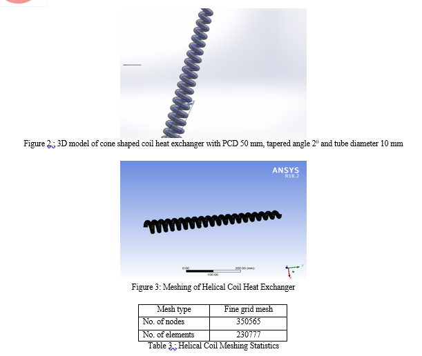
CFD analysis of helical coil heat exchanger by using ANSYS 18.2
Pre-processing:
CAD Model: Generation of 3D model by using SOLIDWORKS and exporting to the IGES format and then import in ANSYS fluent 18.2.
CAD modelling / meshing has been done by following steps
a. Open Solid works then select part for modelling.
b. In part modelling select circle of 50 mm diameter.
c. After that select helix geometry of pitch 25 mm, tapered angle 20 and length 500 mm.
d. Now again come to circle command and at the end of helix pierce it.
Then select sweep command and in sweep command selecting tube then click to curve and geometry came.
- Step 3
Fluent Setup:
After mesh setup generation define the following steps in the ANSYS fluent 18.2.
- Problem Type -3D solid
- Type of Solver – pressure
- Physical Model – viscous k- two equation turbulence model
- Mixture- mixture
- Step 4
Fluid Property
|
Type of fluid |
Water |
|
Density (ρ) |
998.2 kg/m3 |
|
Viscosity (µ) |
0.2 kg/m-s |
|
Specific heat (Cp ) |
1.67 KJ/Kg-K |
|
Thermal conductivity ( k) |
0.162Watt/mK |
Table 4: Properties of water
|
Type of fluid |
Copper Oxide Nanofluid |
|
Density (ρ) |
6000 kg/m3 |
|
Viscosity (µ) |
0.00001004 kg/m-s |
|
Specific heat (Cp ) |
551 J/Kg-K |
|
Thermal conductivity ( k) |
33 Watt/K |
Table 5: Properties of Copper oxide
|
Type of fluid |
Ethylene Glycol |
|
Density (ρ) |
1111.4 kg/m3 |
|
Viscosity (µ) |
0.0157 kg/m-s |
|
Specific heat (Cp ) |
2415 J/Kg-K |
|
Thermal conductivity (k) |
0.252 Watt/mK |
Table 6: Properties of Ethylene glycol
V. SOLUTION
A. Solution Method
Pressure - Velocity - Coupling – Scheme - Simple
- Pressure – standard pressure
- Momentum- 2nd order
- Turbulence –kinetic energy 2nd order
- Turbulence dissipation rate 2nd order
B. Solution Initialisation
Initiate the solution to get the initial solution for the problem.
- Run Solution: Run the solution by giving 600 number of iteration for solving the convers.
- Post Processing: For viewing and interpret of result, the result can be viewed in various formats like graph, value, animations etc.
VI. RESULTS & DISCUSSION
The pressure drop information were collected for the configuration of cone formed coil for the CuO nanofluid as water & ethane glycol as its base fluid. The varied effects of mass rate were ascertained.
- CFD computations were in serious trouble atomic number 13 cone curled tube.
- Performance parameters adopted for comparison of pressure drop and temperature distribution all told the cases.
- Result of pressure drop on the cone formed coil by mistreatment CuO nanofluid as ethanediol as its base fluid at zero.005 mass rate.
|
Case |
Tube diameter |
Fluid |
Pressure drop (Pa) |
|
1 |
10 mm |
CuO Nano fluid |
20589 |
Table 9: Effect of pressure drop on the cone shaped coil by using CuO nanofluid as ethylene glycol as its base fluid at 0.005 mass flow rate.
4. Effect of temperature on the cone shaped coil by using CuO nanofluid as ethylene glycol as its base fluid at 0.005 mass flow rate.
|
Case |
Tube diameter |
Fluid |
Temperature (K) |
|
1 |
10 mm |
CuO Nano fluid |
339.4 |
Table 10: Effect of temperature on the cone shaped coil by using CuO nanofluid as ethylene glycol as its base fluid at 0.005 mass flow rate.
5. Effect of pressure drop on the cone shaped coil by using CuO nanofluid as ethylene glycol as its base fluid at 0.02 mass flow rate.
|
Case |
Tube diameter |
Fluid |
Pressure drop (Pa) |
|
1 |
10 mm |
CuO Nano fluid |
77284 |
Table 11 : . Effect of pressure drop on the cone shaped helical coil by using CuO nanofluid as ethylene glycol as its base fluid.
6. Effect of temperature on the cone shaped coil by using CuO nanofluid as ethylene glycol as its base fluid at 0.02 mass flow rate.
|
Case |
Tube diameter |
Fluid |
Temperature (K) |
|
1 |
10 mm |
CuO Nano fluid |
338.4 |
Table 12: Effect of Temperature on the cone shaped helical coil by using CuO nanofluid with ethylene glycol as its base fluid on high pressure
7. Effect of pressure drop on the cone shaped coil by using CuO nanofluid as water as its base fluid at 0.005 mass flow rate.
|
Case |
Tube diameter |
Fluid |
Pressure drop (Pa) |
|
1 |
10 mm |
CuO Nano fluid |
1578 |
Table 13: Effect of pressure drop on the cone shaped helical coil by using CuO nanofluid as water as its base fluid.
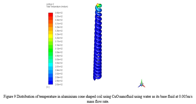
8. Effect of temperature on the cone shaped coil by using CuO nanofluid as water as its base fluid at 0.005 mass flow rate.
|
Case |
Tube diameter |
Fluid |
Temperature (K) |
|
1 |
10 mm |
CuO Nano fluid |
338.7 |
Table 14: Effect of temperature on the cone shaped helical coil by using CuO nanofluid as water as its base fluid on high pressure.
9. Effect of pressure drop on the cone shaped coil by using CuO nanofluid as water as its base fluid at 0.02 mass flow rate.
|
Case |
Tube diameter |
Fluid |
Pressure drop (Pa) |
|
1 |
10 mm |
CuO Nano fluid |
6541 |
Table 15: Effect of pressure drop on the cone shaped helical coil by using CuO nanofluid as water as its base fluid.
10. Effect of temperature on the cone shaped coil by using CuO nanofluid as water as its base fluid at 0.02 mass flow rate.
|
Case |
Tube diameter |
Fluid |
Temperature (K) |
|
1 |
10 mm |
CuO Nano fluid |
339.2 |
Table 16: Effect of temperature on the cone shaped helical coil by using CuO nanofluid as water as its base fluid on high pressure.
a. Case-1: Tube Diameter is 10 mm, CuO nanofluid is used as ethylene glycol as its base fluid in aluminium cone shaped coil, Pressure drop is 20589 Pa at 0.005m/s mass flow rate
At a tube diameter of ten metric linear unit, the most pressure drop get is 20589 Pa. ab initio at all-time low section of the coil the pressure drop is 113 Pa and at the center portion pressure drop is 1038 Pa, from lower to middle portion of coil there's increase in pressure drop of 925 Pa. From middle to prime portion of coil there's unendingly increase in pressure drop from 1038 Pa to 20589 Pa in atomic number 13 cone formed coil mistreatment CuO nanofluid mistreatment ethanediol as a base fluid at zero.005m/s mass rate.
b. Case-2: Tube Diameter is 10 mm, CuO nanofluid is used as water as its base fluid in aluminium cone shaped coil, pressure drop is 1578 Pa at 0.005m/s mass flow rate.
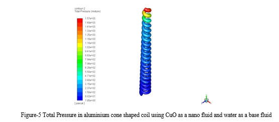
At a tube diameter of ten metric linear unit, the most pressure drop get is 1578 Pa. ab initio at all-time low section of the coil the pressure drop is a pair of Pa and at the center portion pressure drop is eighty three Pa, from lower to middle portion of coil there's increase in pressure drop of eighty one Pa. From middle to prime portion of coil there's unendingly increase in pressure drop from eighty three Pa to 1578 Pa in atomic number 13 cone formed coil mistreatment CuO nanofluid and water as a base fluid at zero.005m/s mass rate.
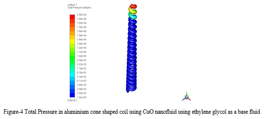
c. Case-3: Tube Diameter is 10 mm, CuO nanofluid is used as ethylene glycol as its base fluid in aluminium cone shaped coil, pressure drop is 77284 Pa at 0.02m/s mass flow rate.
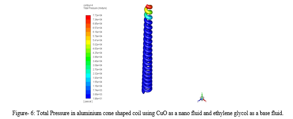
At a tube diameter of ten metric linear unit, the most pressure drop get is 77284 Pa. ab initio at all-time low section of the coil the pressure drop is nineteen.8 Pa and at the center portion pressure drop is 3809 Pa, from lower to middle portion of coil there's increase in pressure drop of 3798.2Pa. From middle to prime portion of coil there's unendingly increase in pressure drop from 3809 Pa to 77284 Pa in atomic number 13 cone formed coil mistreatment CuO nanofluid mistreatment ethanediol as a base fluid at zero.02m/s mass rate.
d. Case-4: Tube Diameter is 10 mm, CuO nanofluid is used as water as its base fluid in aluminium cone shaped coil, pressure drop is 6541 Pa at 0.02m/s mass flow rate.
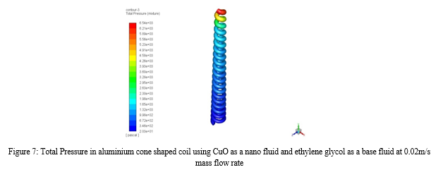
At a tube diameter of ten metric linear unit, the most pressure drop get is 6541 Pa. ab initio at all-time low section of the coil the pressure drop is twenty.3 Pa and at the center portion pressure drop is three46.2 Pa, from lower to middle portion of coil there's increase in pressure drop of 325.9 Pa. From middle to prime portion of coil there's unendingly increase in pressure drop from 346.2 Pa to 6541Pa in atomic number 13 cone formed coil mistreatment CuO nanofluid mistreatment water as a base fluid at zero.02 m/s mass rate.
e. Case-5: Tube Diameter is 10 mm, CuO nanofluid is used as ethylene glycol as its base fluid in aluminium shaped coil, Max temperature is 339.4K at 0.005m/s mass flow rate.

f. Case 6: Tube Diameter is 10 mm, CuO nanofluid is used as water as its base fluid in aluminium cone shaped coil, Max temperature is 338.7K at 0.005m/s mass flow rate.
g. Case 7: Tube Diameter is 10 mm, CuO nanofluid is used as ethylene glycol as its base fluid in aluminium cone shaped coil, Max temperature is 338.4K at 0.02m/s mass flow rate.
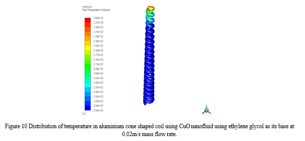
h. Case 8: Tube Diameter is 10 mm, CuO nanofluid is used as ethylene glycol as its base fluid in aluminium cone shaped coil, Max temperature is 339.2K at 0.02m/s mass flow rate.
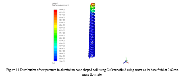
From on top of it's clear that after we used the CuO nanofluid mistreatment ethanediol as a base fluid at zero.02m/s mass rate then pressure drops will increase in CuO as a result of presence of metal particles additionally the} base fluid properties and also mass rate rate is bigger than previous. The numerical study considers the result of CuO nanofluid mistreatment ethanediol and water as its base fluid at zero.005m/s & 0.02m/s mass rate on the flow and warmth transfer characteristics of tube. The thermal belongings of fluid area unit minor as compared to nanofluid. Nano fluids have Nano particles of solid constituents that increase the thermal properties of Nano fluid conjointly as a result of vortex flow the pressure drop are going to be enlarged.
|
Properties |
Maximum Pressure |
Max. Temp. |
|
CuO nanofluid using ethylene glycol as a base fluid in cone shaped coil heat exchanger at 0.005m/s mass flow rate |
20589 Pa |
339.4 K |
|
CuO nanofluid using water as a base fluid in cone shaped coil heat exchanger at 0.005m/s mass flow rate |
1578 Pa |
338.7 K |
|
CuO nanofluid using ethylene glycol as a base fluid in cone shaped coil heat exchanger at 0.02m/s mass flow rate |
77284 Pa |
338.4 K |
|
CuO nanofluid using water as a base fluid in cone shaped coil heat exchanger at 0.02m/s mass flow rate |
6541 Pa |
339.2 K |
Table No. 17 CFD Analysis results
Conclusion
In this paper, analytical investigations are done on the cone shape coil heat exchanger, to determine pressure drop and temperature distribution of an ethylene glycol and water as a base fluid and a CuO as a nanofluid on cone shaped coil flowing under laminar flow conditions. By observing the CFD analysis results, we know that the material which has high thermal conductivity that fluid will give high pressure drop and also a material which is good in its properties. The pressure drop is more in CuO nanofluid with ethylene glycol as a base fluid in cone shaped helical coil heat exchanger at 0.02m/s mass flow rate.
References
[1] GA Sheikhzadeh, M. Ebrahim Qomi, N. Hajialigol, Shinde DigVijay D. 2013 – “Heat Transfer Analysis of a Cone Shaped Helical Coil Heat Exchanger” International Journal of Innovations in Engineering and Technology Volume 3, Issue 1, Page 56-62. [2] Mukesh Kumar 2017 – “Heat Transfer Analysis of Cone Shaped Helical Coil Heat Exchanger of Different Pitches and Diameter” International Journal of Advance Research in Science & Engineering, Volume No.6, Issue No.7, Page 1171-1183. [3] V. Murali Krishna 2016 ?Heat Transfer Enhancement by using ZnO Water Nanofluid in a Concentric Tube Heat Exchanger under Forced Convection Conditions? International Journal of Innovations in Engineering and Technology, Volume-7, Page 177-184. [4] Hemasunder Banka, Dr. V. Vikram Reddy, M. Radhika 2016, ?CFD Analysis of Shell and Tube Heat Exchanger using Titanium Carbide, Titanium Nitride and Zinc Oxide Nanofluid? International Journal of Innovations in Engineering and Technology, Special Issue, Page 315-322. [5] K. Abdul Hamid, W. H. Azmi, RIzalman Mamat, N. A. Usri and Gohalamhassan Najafi 2015, ?Effect of Titanium Oxide Nanofluid Concentration on Pressure drop? ARPN Journal of Engineering and Applied Sciences, Volume 10, Page 7815-7820. [6] Palanisamy, K. P.C. Mukesh Kumar 2019, ?Experimental investigation on convective heat transfer and pressure drop of cone helically coiled tube heat exchanger using carbon nanotubes/ water nanofluids?, Elsevier – Heliyon 5. Sunil Kumar, Dr. DK Gupta 2020, ?Optimising Design and analysis on the Helically Coiled Tube Heat Exchanger carrying Nanofluids by providing fins? Smart Moves Journal IJO Science, Volume 6, Page 23-31. [7] Shiva Kumar, K Vasudev Karanth 2013, ?Numerical analysis of a Helical Coiled Heat Exchanger using CFD? International Journal of Thermal Technologies, Volume 3, Page 126-130 [8] Sunil Kumar, Dr. DK Gupta 2020, “Optimising Design and analysis on the Helically Coiled Tube Heat Exchanger carrying Nanofluids by providing fins” Smart Moves Journal IJO Science, Volume 6, Page 23-31. [9] B. Chinna Ankanna, B. Sidda Reddy 2014, ?Performance Analysis of Fabricated Helical Coil Heat Exchanger?, International Journal of Engineering & Research, Volume 3, Page 33-39. [10] M. Balachandaran 2015, ?Experimental and CFD study of a Helical Coil Heat Exchanger using Water as Fluid? International Journal of Mechanical and Production Engineering, Volume 3, Page 87-91. [11] Ashkan Alimoradi 2017, ?Study of thermal effectiveness and its relation with NTU in Shell and helically coiled tube heat exchanger? Elsevier Case Studies in Thermal Engineering, Volume 9, Page 100–107. [12] Vinita Sisodiya, Dr. Ankur Geete 2016 ?Heat Transfer analysis of Helical coil Heat Exchanger with Al2O3 Nanofluid? International Journal of Engineering and Technology, Volume 3, Page 366-370. [13] Fakoor-Pakdaman, M.A. Akhavan- Behabadi,P. Razi 2013, ?An empirical study on the pressure drop characteristics of Nanofluid flow inside helically coiled tubes? International Journal of Thermal Sciences, Volume 65, Page 206-213. [14] T. Srinivas, A. Venu Vinod 2015, ?Heat Transfer Enhancement using CuO/Water Nanofluid in a Shell and Helical Coil Heat Exchanger? Elsevier, Volume 127, Page 1271-1277. [15] Tushar A. Sinha, Amit Kumar, Nikhilesh Bhargava and Soumya S Mallick 2014, ?An Experimental Investigation into the Thermal Properties of Nano Fluid? Applied Mechanical Engineering, Volume 4, Issue 1. [16] Jaafar Albadr, Satinder Tayal, Mushtaq Alasadi 2013 ?Heat transfer through heat exchanger using Al2O3 nanofluid at different concentrations? Elsevier, Volume-1, Page 38-44. [17] Jayakumar J. S., S.M. Mahajani, J.C. Mandal, P.K. Vijayan, Rohidas Bhoi, 2008, ?Experimental and CFD estimation of heat transfer in helically coiled heat exchangers? Chemical Engineering Research and Design, Volume 86, Page 221-232. [18] Amar Raj Singh Suri, Anil Kumar, Rajesh Maithani 2017, ?Effect of square wings in multiple square perforated twisted tapes on fluid flow and heat transfer of heat exchanger tube? Elsevier Case Studies in Thermal Engineering, Volume 10, Page 28-43. [19] Ram Kishan, Devendra Singh, Ajay Kumar Sharma 2020, ?CFD Analysis of Heat Echanger using Ansys Fluent?, International Journal of Mechanical Engineering and Technology?, Volume 11, Page 1-9. [20] N. K. Chavda, Jay R. Patel, t H. Patel, Atul P. Parmar 2014 ?Effect of nanofluid on heat transfer characteristics of double pipe heat exchanger: part-1: effect of aluminum oxide nanofluid? International Journal of Research in Engineering and Technology, Volume-3, Page 42-52. [21] Sunny Sobby P, Maahaske Siddharth D, Parikh Yash B. Numerical simulation of a tube in tube helical coil heat exchanger using CFD. International journal of applied engineering research 2014; Vol. 9: pp. 5209-5220. [22] Pramod Deshmukh, Vikram D Patil, Prof. Baviskar Devakant 2016 ?CFD analysis of heat transfer in helical coil tube in tube heat exchanger? International Journal of Innovation in Engineering Research and Technology, Volume 3, Issue 1. [23] Amol Bari, Hemant Bhutte, Nirmal Waykole, Ajeet Yadav, Swapnil Mane 2016 ?Study of tube in tube concentric parallel flow heat exchanger using nanofluid? International Journal of Advanced Research, Volume 4, Page 1376-1383. [24] Wandong Zheng, Huan Zheng, Shijun You, Tianzhen Ye 2016 ?The thermal characteristics of a helical coil heat exchanger for seawater source heat pump in cold winter? Elsevier, Volume-146, Page 549-558. [25] Changnian Chen, Jitian Han and Li Shao 2017 ?The characteristics of Pressure Drop and Heat transfer of Coils Used in Solar Collectors? Elsevier, Volume-7, Page 351-357. [26] Baghel Rakesh & Upadhayaya Sushant. Effect of coil diameter in archimedan spiral coil. International journal of applied engineering research 2013; Vol. 8: pp. 2151- 2156. [27] Ankanna Chinna B, Reddy Sidda B. Performance analysis of fabricated helical coil heat exchanger. International journal of engineering research 2014; Vol. 3: pp.33-39. [28] A K Singh 2008 “Thermal Conductivity of Nano fluids” Defence Science Journal, Volume 58, Page 600-607.
Copyright
Copyright © 2022 Navneet Kumar, Vijaykant Pandey. This is an open access article distributed under the Creative Commons Attribution License, which permits unrestricted use, distribution, and reproduction in any medium, provided the original work is properly cited.

Download Paper
Paper Id : IJRASET47069
Publish Date : 2022-10-12
ISSN : 2321-9653
Publisher Name : IJRASET
DOI Link : Click Here
 Submit Paper Online