

Ijraset Journal For Research in Applied Science and Engineering Technology
Design and Analysis of Barrel Vault Space Frame Structure
Authors: Naveen AJ, Dr. R. Subhash Chandra Bose, Navya K S
DOI Link: https://doi.org/10.22214/ijraset.2022.45645
Certificate: View Certificate
Abstract
The point of this paper is to concentrate on the plan and investigation of extraordinary kind barrel vault space outline 3d bracket type structure. Furthermore, here investigated and intended for angle proportion with thought of burdens like dead burden, live burden, wind load, administrations, seismic, temperature loads and burden mixes. Space outline is planned by the IS codes alluded to in the plan by a limited component based PC program. the heaps are depicted in the stacking segment have been applied on the design as per IS875 section 1, 2,3 and 5 for dead loads, wind loads and burden mixes. IS1893 section 1 and 4 for seismic burden. this work prompts the correlation on range greatest avoidance, self-weight and cost measures.
Introduction
I. INTRODUCTION
A developing interest in space outline structures has been seen overall over the course of the past 50 years. The quest for new primary structures to oblige enormous unhampered regions has forever been the fundamental target of designers and architects. With the appearance of new structure methods and development materials, space outlines regularly give the right response and fulfill the necessities for daintiness, economy, and quick development. Critical headway has been made during the time spent the improvement of the space outline. A lot of hypothetical and trial research programs was completed by numerous colleges and examination organizations in different nations. Subsequently, a lot of helpful data has been dispersed and productive outcomes have been incorporated. In the beyond couple of many years, the multiplication of the space outline was predominantly because of its extraordinary primary potential and visual excellence. New and creative utilizations of room outlines are being shown in the absolute scope of building types, like games fields, presentation structures, gathering lobbies, transportation terminals, plane overhangs, studios, and distribution centers. They have been utilized on lengthy range rooftops, yet in addition on mid-and limited ability to focus as rooftops, floors, outside walls, and overhangs. Many intriguing ventures have been planned and developed all around the world utilizing different arrangements. A few significant variables that impact the fast improvement of the space edge can be refered to as follows. To begin with, the quest for huge indoor space has forever been the focal point of human exercises. Thus, sports competitions, social exhibitions, mass gatherings, and shows can be held under one rooftop. The cutting edge creation and the necessities of more noteworthy functional effectiveness likewise encouraged interest for enormous space with a base impedance from inner backings. The space outline gives the advantage that the inside space can be utilized in various ways and hence is unmistakably appropriate for such prerequisites.
II. LITERATURE REVIEW
SARIKAB.SHINDE, M. SHIMPALE (2015) In this paper is to the concentrate twofold layer barrel vault (DLBV) of 3D section type. Barrel vault are notable way to deal with navigating huge locales with few middles of the street maintains Truss type twofold layer barrel vault is clear fundamental improvement contained association of longitudinal, get over and upheld part with curve in one course in a manner of speaking. Support type barrel vault are researched and planned for different weight, for instance, live weight, wind load and the blend of weights. The section type barrel vault is arranged by IS: 800-2007and assessment performed by using STAAD. Star 2007. This work prompts the assessment on range, most outrageous redirection, self-weight and cost models
K. Selvam, R. Divyameena (2016) This adventure deals with the smoothing out of steel space support. Smoothing out is a course of persecuting all people present in the development to least use as such ensuring the utilization extent of each and every part more than 80%. It is to be seen that the hidden properties not be compromised. The development should be made of cutoff state plan and should be basically maintained housetop. Space support setup is the technique for consigning a plan using skeleton-type approach, instead of standard piece-by-piece or ground-up improvement. Free of advantage of the plan, down to earth capably of development picks achievement of it. Hereafter the space support was arranged and redesigned during our endeavor. The shapes were changed for the best result and smoothed out shape was achieved. From this cutting-edge shape primers were finished with different profundities in conclusion shut the best.
Dhananjay's. Pawar, S. Abdulla, U. Phadnis, Ravi.G. maske, Raju. S. Shinde4 (2015)
The even improvement is the most express part of quake movement considering its fortitude and in light of the fact that developments are all around favored expected to go against gravity over level powers. These powers produce tremendous nerves, strains, mutilation and evacuation particularly in tall developments. To continue evacuating inside limit normally supporting is given in steel structure. Bracings are generally used to augment even immovability, equal strength as well as sidelong adequacy of the packaging. Assortments in the portion robustness can affect the technique for disillusionment and equal solidness of the supporting. In this study steel frame is exhibited and analyzed three Parts viz.,
- Model without Steel propping (uncovered outline),
- Model totally with completely supported steel outline (Cross propping),
- Model totally with completely supported steel outline (Single diagonal propping)
Amit Kumar, Anant Kumar, Shyam Kishor Kumar, Krishna Murari (2014) The seismic lethargy powers made at its floor levels are traveled through the various shafts and segments to the ground. The failure of a segment can impacts the steadfastness of the whole construction, yet the mistake of a bar causes bound influence. Along these lines, it is more astute to make shafts to be the adaptable disappointment focuses than areas. This procedure for arranging RC structures is known as the strong portion weak shaft plan system. Expecting the packaging is arranged in view of strong area weak bar thought the possible results of breakdown on account of impact parts can be completely abstained from. In multi story frame this can be achieved by allowing the plastic turns to outline, in a predestined game plan right at the terminations of the large number of shafts while the segments remain essentially in flexible stage and by avoiding shear technique for disillusionments in sections and bars. This strategy for design is known as Capacity based plan which would be the likely arrangement hypothesis for seismic quake well thought out plan of multi-story upheld significant advantages.
Jayashree's, R. RakulBharatwaj
The utilization of prestressing advancement and the improvement of fundamental thoughts and game plans are furthermore associated with current space structures, including composite space upholds, open-web network structures, polyhedron space frame structures, deficient twofold layer cross segment shells, interface remained grid structures, tree-type structures, prestressed segmental steel structures, and so on. This paper gives a review of the fundamental ascribes and sensible applications in China of current rigid space structures, present day versatile space plans and current resolute versatile joined space structures.
Fattah K. Abbas Adel Abdul Jabbar AL-Waily (2000) It is gathered that regardless of the way that how much extraordinary turn among bar and segment is decently minimal in the stacked packaging structures, this differential turn essentially influences the numerical direct of edge structures and consequently on the arrangement of their parts. It has been shown that the prospect of semi-rigid relationship in the examination of packaging structures is crucial.
Santosh Kumar (2007) This paper portrays an exploratory assessment concerning a half-scale basic model of a sun-situated finder twofold layer tensegrity space structure that was at first proposed to cover the new National Opera House in Athens, Greece. The fundamental scale model has a 5m territory with cubic modules of 1.25m edge length. The fundamental inspiration driving the preliminary is to look at the advancement gathering, and, explicitly, the pre-pushing of the plan. A novel pre-centering plan is used, where the top and base level people are jacked isolated, and a vertical strain part is extended.
Before long, affirmation of pre-centering is huge, and a sensible procedure for assessing prestress in the corner to corner people in the field through vibration assessments is portrayed.
III. OBJECTIVES
- To plan the space outline.
- To show that the space casing can be planned and executed to the length of 100m range.
- To demonstrate that space outline is a light weight structure.
- To review and show how the heap move happens in the space outline.
IV. AIM AND SCOPE OF THE PROJECT
- The scientists inferred that the spatial designs are more appropriate for long-range structures and are valuable to cover huge regions with practically no mid deterrents. The heaps are consistently moved with the goal that these designs are stiffer and gain high strength.
- The space outline structures are light in weight and can be framed into different shapes which give a pleasant stylish appearance to the design.
- The different limited component programming like STADD Pro, SAP 2000, ANSYS, ABAQUS are helpful for detail investigation and plan of room outline structure.
- The different procedures, for example, composite space outline structures, over-reinforced the top harmony individuals are, utilization of heavier segments are utilized for upgrading the effectiveness of the construction.
- The composite space support shows preferable execution over non-composite space bracket to diminish the pressure powers in the top harmony individuals. By decreasing the pressure powers the clasping disappointment of top harmony individuals likewise forestalled. The composite space bracket framework builds the productivity of the design.
V. METHODOLOGY
- To design the space frame for a 100m span.
- To perform the analysis for all load combinations using STAAD PRO.
- To make it safe under worst seismic conditions.
VI. SYSTEM MODELLING
A. Applicable Design Codes
- Space Frame is designed according to the IS codes referred to in the design by a finite element based computer program.
- The loads as described in the Loading Section have been applied on the structure in accordance with:
- IS 875-Part-1, 2, 3&5 for Dead loads, Imposed loads, Wind loads & Load combinations.
- IS 1893-Part-1 & 4 for Seismic loading.
B. Design Assumptions
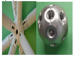
- The space frame has been designed as double layer structure with a rectangular grid as a top layer offset from the bottom grid and interconnected with diagonals. .
- The space frame is idealized as space truss assembled of straight linear elements connected at nodes, so that the primary load transfer action is axial. In the analysis therefore, the mutual connection of linear elements at the joints is considered pinned.
- The roof loading will be transferred from roof sheeting to space frame nodes via purlins that are connected to nodes by means of purlins stools and flanges.
- No direct load will be applied to space frame members. If applied rarely, those members will be checked for combined axial and bending effects of member.
- Purlins will be designed as bending (flexural) members that receive uniformly distributed load from sheeting.
- Space frame rests on RCC Pedestal. The supporting base plate is fixed through an anchorage system.
- Space frame is designed as per Limit state Design IS 800 2007.
C. Introduction
This design document shows the structural design calculation and basic arrangement of Space Frame structure proposed Height of structure is considered to be +15.75 m.
D. Structural Details
|
Structure Description |
Details |
|
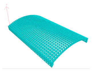
Structure type |
Barrel Vault. |
|
Configuration |
Space Frame. |
|
Typical module size |
2981 mm x 3000 mm & Varies. |
|
System Depth |
2000 mm & Varies. |
|
Overall length, L |
100.00 m |
|
Overall width, w |
64.20 m |
|
Height of the structure, h |
15.75 m |
E. Seismic Loads
Horizontal load per space frame = 15kg/node in X and Y direction.
In accordance with IS 1893-2016 Part-1
Location of building: Bengaluru
Seismic Zone: II
Height of the building = 17.5 m approx.
The approximate fundamental natural period of vibration Ta = 0.085 h0.75 for steel frame buildings
Hence Ta = 0.605 sec
Design horizontal acceleration spectrum value Ah = (Z I/ 2R) (Sa/g)
Zone factor Z= 0.10
Importance factor I: 1.5
Response reduction factor R= 4
Type of soil: Soft Soil
From Fig. 2, Spectral acceleration Sa/g = 2.5
Percentage of damping = 2%. Hence, from table 3, multiplying factor for Ah= 1.4
Thus Ah = 0.0469
Calculation Seismic weight (W)
Dead load on the structure (inclusive of self-weight) =40.5 kg/m2 (S.W+ Purlin weight + Roof Load+ Services)
Number of nodes: 1900
Total surface area (As modeled in software) = 8123 m2
Total seismic weight W = A x Total Load = 24673.61
Design Seismic Base Shear Vb= Ah x W = 0.0469*24673.61 = 1157.19 kg
Seismic load per node = 24673.61 /1900= 12.98 kg say 15 kg/Node
This load is applied along positive and negative directions of two horizontal axes X and Y of the software. i.e. (E+X), (E-X), (E+Y), (E-Y)
F. Temperature Loads
Differential temperature of ± 15° has been considered.
G. Load Cases
Load Name: Load Type
SELF WEIGHT: S.W
DEAD + Services LOADS: D.L
LIVE LOADS: L.L
ROOF WIND LOADS – /+CPe: W(+/-X),W(+/-Y)
WALL CLADDING WIND W(+/-X),W(+/-Y)
SEISMIC LOADS (X direction): E(+X)
SEISMIC LOADS (Z direction): E(+Z)
TEMPERATURE LOADS: T
H. Load Combinations: - (According to IS 800 2007 LSD)
Load Cases
- Self-Weight (S.W)
- Dead Load (D.L)
- Live Load (L.L)
- Services
- Roof Wind Load -0degree(Windward Side )
- Roof Wind Load -0degree(Centre)
- Roof Wind Load -0degree(Leeward Side)
- Roof Wind Load-90degree( Windward Side)
- Roof Wind Load-90degree(Leeward Side)
- Cladding Wind Load -0degree(Windward Side )
- Cladding Wind Load -0degree(Leeward Side )
- Cladding Wind Load -90degree(Windward Side )
- Cladding Wind Load -90degree(Leeward Side )
- Seismic +X (EQ)
- Seismic +Z (EQ)
- Temperature (T)
I. Load Combinations
- Uniform Wind Pressure is applied in each wind load cases
- The effect of net pressure coefficient is simulated by applying multiplication factor along with load factor in load combination
- Co-efficient to load combinations factor multiplication are as below
From Code IS 875-2015 Part-3
J. Material Specifications
Tubular sections: Conforming to IS: 1239 or equivalent of grade Yst 310 / ASTM A53. Minimum yield strength 310N/mm2
Cones / end adaptors: Proprietary end connectors made of grade 250 / ASTM A36 steel. Minimum yield strength 250 N/mm2
High Strength Bolts: Proprietary high strength bolts grade 10.9.
|
IS 806 : 1968 |
Code of practice for use of steel tubes in general building construction |
|
IS 875 : Part 1 : 1987 |
Code of practice for design loads (other than earthquake)for buildings and structures Part 1 Dead loads - Unit weights of building material and stored materials (Incorporating IS:1911-1967) |
|
IS 875 : Part 2 : 1987 |
Code of practice for design loads (other than earthquake) for buildings and structures: Part 2 Imposed loads |
|
IS 875 : Part 3 : 2015 |
Code of Practice for Design Loads (Other than Earthquake) for Buildings and Structures - Part 3 : Wind Loads |
|
IS 1893 : Part 1 : 2016 |
Criteria for Earthquake Resistant Design of Structures - Part 1 : General Provisions and Buildings |
|
IS 1239 : Part 1: 2004 |
Steel tubes, tubular and other wrought Steel fittings — specification Part 1 : Steel Tubes |
|
IS 1161 : 1998 |
Steel Tubes for Structural Purposes - Specification |
|
ASTM A1085 |
HSS: Sections and Properties |
|
IS 2062 : 1999 |
Steel for General Structural Purposes - Specification |
|
IS 4923 : 1997 |
Hollow steel sections for structural use |
|
IS 3757 : 1985 |
Specification for high strength structural bolts.
|
|
IS 4000 : 2003 |
Code of practice for high strength bolts in steel structures. |
K. Properties of Steel
Density 7850 kg/m3
Modulus of Elasticity 2.10 E+05 N/mm2
Poisson’s ratio 0.3
Co eff of thermal expansion 12.0 E-06 / Deg C
L. Codes of Practice
Conclusion
Space structure arrangements are rich and amazing however, except if the creator is furnished with reasonable applied instruments, the undertaking of age of math is incredibly troublesome. Formex variable based math remains solitary as a variable based math which gives a strong numerical premise to new way to deal with information age. Formex setup is arising part of age of math of skeletal designs. It supplements the human creative mind and permits intellectually pictured setup to communicate in a compact and exquisite way. Formian programming gives a stage to formex design handling, age of different kinds of construction like supported arches, frameworks, barrel vaults, pyramid, towers. This product created the math as well as incorporated with other programming like Autodesk Robot Structural Analysis. Notwithstanding this it is likewise produced the information trade record (*.dxf), which can imported in greater part of CAD bundles. This office is proficiently taken advantage of in present work. Loads, matrix size, profundity and rise meaningfully affect the streamlining of barrel vaults likewise number gathering in each layer (in model something like four). The uprooting in the best arrangement is 4.4 cm (limit 19.2 cm) proposes that the design is exceptionally unbending and may look for stunningly better arrangements. The best typical powers (298 KN) at base layer happened near limit line. The quantity of supports on one side was 5 - increment their unquestionably will cause improvement arrangements. An expansion in level (ascent) will decrease powers in the construction yet brings about a general expansion long and weight increment, tragically.
References
[1] C. Vatansever, “Investigation of buckled truss bars of a space truss roof system,” Elsevier, EngineeringAnalysis, vol. 106, August 2019. [2] B. Basil, B. S. Lakshmi, et al., “Space truss design using STADD. Pro Software,” IRJET, Vol. 6, Issue. 4, pp. 3777- 3782, April 2019. [3] G. D. Lorenzo, E. Babilio, A. Formisano and R. Landolfo, “Innovative steel 3D trusses for preservating archaeological sites: Design and preliminary results,” Elsevier, Journal of Construction Steel Research, Vol. 154, pp. 250-262, Dec 2018. [4] F. Fu and G. A. R. Parke, “Assessment of the progressive Collapse Resistance of Double-Layer Grid Space Structures Using Implicit and Explicit Methods,” International Journal of Steel Structures, vol.18,Issue. 3, pp. 831–842, April 2018. [5] P. Sangeetha, “Parametric study on the stiffness and energy.
Copyright
Copyright © 2022 Naveen AJ, Dr. R. Subhash Chandra Bose, Navya K S. This is an open access article distributed under the Creative Commons Attribution License, which permits unrestricted use, distribution, and reproduction in any medium, provided the original work is properly cited.

Download Paper
Paper Id : IJRASET45645
Publish Date : 2022-07-15
ISSN : 2321-9653
Publisher Name : IJRASET
DOI Link : Click Here
 Submit Paper Online