

Ijraset Journal For Research in Applied Science and Engineering Technology
Review on Design and Analysis of Drill Head of Boring Machine by using Vibration Conditioning Monitoring
Authors: Dipali Bhoyar, Sandeep Kumar
DOI Link: https://doi.org/10.22214/ijraset.2023.51781
Certificate: View Certificate
Abstract
In terms of both productivity and product quality, machine tools are now held to high standards in the industrial sector. Vibration is a crucial indicator of a product\\\'s quality. If the patterns of vibration produced by machine tools during cutting operations are recognised, the structure of the machine tool may be built in a way that separates its frequency response from the imposed frequency. The most effective method for managing all machining operations and maintaining machinery operation is tool condition monitoring. Monitoring tool condition affects production costs, tool life expectancy, tool quality, dimensional accuracy within a given tolerance, and surface polish in a machine shop. Here, the machining process is entirely dependent on the operator\\\'s whims and preferences. So, it is more difficult for a novice operator to identify the tool wear point and it is more difficult for the operator to operate the machine. A systematic process is needed for the machining procedure to get around this challenge. Determining the inherent frequency and mode forms of the radial drilling machine construction is the aim of this research as a consequence. Finite element analysis was used to identify the innate frequencies and mode shapes of the radial drilling machine structure.
Introduction
I. INTRODUCTION
Drilled holes can be identified by their sharp edge on the entrance side and by the presence of burrs on the exit side (unless they have been removed). Furthermore, helical feed marks are typically visible inside the hole. [3] operation like By reducing residual stresses around the hole openings and producing a very thin (lean) layer of highly strained and noticeably disturbed material on the freshly created surfaces, drilling can affect the mechanical characteristics of the workpiece. This makes the workpiece more vulnerable to corrosion at the stressed surfaces and more prone to crack formation. These harmful situations can be avoided by performing a completion procedure. The flutes on fluted drill bits are used to scrape out the chips.
The shape of the chips might take the form of microscopic flakes or long spirals, depending on the material and process factors. An procedure known as "boring" is used to produce circular internal profiles on a drilled hole or a hole created using any other process. It makes use of a boring bar, a single point cutting instrument. Both the boring bar and the workpiece can be rotated during a boring operation. Boring machines, also known as boring mills, are machine tools that have a stationary workpiece that the boring bar rotates against. When a spinning work piece is held in the lathe chuck and a stationary boring bar is positioned in the tool post of the turning machine, boring operations can be carried out. Combination tools: Everyone is aware with a Center Drill, which combines a drill with a countersink and is used for lathe work. There are many other sizes and combinations available, but figure 1 only displays a drive matic drill and countersink. When through-hole components are required, these are most frequently used. For standard twist drills, countersink collars are also available, which aid in adjusting the depth of the countersink in relation to the twist drill's tip.
II.PROBLEM DEFINITION
The most well-known machining technique is drilling, which involves creating round apertures in both metallic and non-metallic materials. Drilling operations account for approximately 75% of all metal-cutting techniques. Drills often have a high length to diameter ratio that makes them suitable for creating large holes, but because of their flexibility, important safety precautions must be taken to maintain accuracy and prevent drill from breaking. As a drill leaves the opposite side of the work, it creates a through hole; during the creation of a blind hole, the drill stays inside the work.Chips generated inside the work piece during the process must exit through the flutes and reach the outside of the apparatus. Friction will be created as the chip is created and withdrawn towards the surface. When the drill bit touches the work piece when drilling a hole, friction and heat are also produced.
In this approach, chip transfer and cutting fluids are two of the most crucial factors that need to be taken into account. Depending on the application, holes formed by drilling are frequently larger than the drill's diameter and must undergo a variety of procedures, such as reaming or sharpening, to improve surface completeness and dimensional accuracy.
One of the most crucial machine tools in a workshop is the drilling machine. On metal work pieces, it was intended to create a cylindrical hole with the desired diameter and depth. Although many machine tools in a business can be used to create holes, drilling machines are created expressly to carry out this task and others like it. In a drilling machine, drilling can be done quickly, cheaply, and over a shorter length of time. By removing metal with the rotating edges of a drill, drilling is the process of creating a cylindrical hole with the desired diameter and depth. The drilling machine's spindle is equipped with the cutting device known as a drill. A centre punch is used to make an indentation mark where it is needed. The spinning drill is activated and fed into the work after being pressed into place. The hole can be dug to the necessary depth.
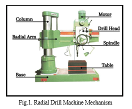
A. Drilling Machine Construction
A drilling machine's foundational components are its base, column, drill head, and spindle. The base constructed of cast iron may rest on a bench, pedestal or floor depending upon the design. Bigger, more powerful devices are grounded to the ground. On top of the base, the column is positioned vertically. It can move the table up and down and is precisely machined. On the top of the column are installed the drill spindle, an electric motor, and a device for controlling the spindle's speed. The spindle receives energy from the electric motor.
B. Drilling Machine Working Principle
This angular drilling machine's operation is initially begun by the universal motor using an AC power supply. There is only one power source in this, and it is the power supply. The indexing mechanism is then controlled, and the desired angle is fixed. To prevent an angle deviation while drilling, a lock nut is fastened to the indexing plate. It will tilt precisely in accordance with drilling requirements. The bevel gear receives the rotational motion of the indexing plate. The shaft is provided this rotating motion, which is then employed to revolve the drill head. The drill head structure's screw will be used to change the cut's depth. Regulator is used to control the motor's speed. After the motor is turned on, the desired angle and speed are fixed, and the drilling process is then carried out. With the aid of our project, we can very precisely create an angle drill hole. Hence, very small angular holes and modifications are possible with our project.
III. OBJECTIVES
The Objective Of This Dissertation Is To Design And Analysis Of Drill Head Of Boring Machine By Using Vibration Conditioning Monitoring. The objectives are:-
- The primary aim of present work is to evaluate the performance of Head Of Boring Machine By Using Vibration Conditioning Monitoring
- To present work is to investigate the effects of process parameters on vibration amplitude, (i.e., displacement) in the drilling to evaluate the performance of drill head over the vibration
- Modeling of all the parts in CATIA.
- Analysis using ANSYS.
- Comparison of results.
- Make research paper and thesis as per the result derived from analysis.
IV. LITERATURE SURVEY
- Liping Liu et al 2017, This paper The tool performance in drilling the composite material is closely tied to a lot of information in this study on the vibration signal. However, because of the piezoelectric accelerometer's limited frequency response capabilities, the monitored vibration signals employed in study were often below 10 kHz. The high frequency vibration signal was therefore disregarded. In this paper, drilling tests on Glass Fiber Reinforced Plastic (GFRP) laminates were performed with candlestick drills. Ten candlestick drills with various drill tip geometry parameters had their high frequency vibration signals investigated and compared in time, frequency, and bispectrum. The findings showed that drilling GFRP laminate produced a high frequency vibration signal exceeding 10 kHz. The factors governing the drill tip shape have an impact on these signals. The variations in these signals' bispectrum energies may be a reflection of alterations in the drills' cutting capabilities and delamination variables.
- Sairaj P Deshmukh et al 2018 , This paper The Special Purpose Machine (SPM) discussed in this study is crucial to raising productivity. Every time we need to manufacture a component, the majority of the machines need settings. Here, one such machine with a multi-spindle drilling head is the SPM created for drilling. The Adftors hold the Components securely in place and horizontally. With hydraulic pressure, the spindle moves in the direction of the component. The drill with a spindle head is powered by an electric motor. The machine is easy to use, quick, and reliable to operate. This increases machining time, accuracy, and productivity.
- Sainath Patil et al 2019 , In order to boost the productivity of machining systems, multi-spindle head machines are discussed in this work. Such machines have spindle heads that may hold a variety of tools to carry out machining operations. The cycle time, which is significantly reduced by parallel machining, is the most notable benefit of adopting multi-spindle machines. Less probability of error, less accumulated tolerance error, and the elimination of tool changes are further advantages. A part that needs to be machined is fastened to the table in a multi-spindle machine like this.
- John Stephen R et.al. 2020, This paper discusses the amplitude of the work piece vibration, which establishes the tool condition following numerous experimental testing, is predicted using Lab View, which is discussed in this study. The characteristic parameter during drill wear represents the increase in RMS value in flank wear in the time domain and also illustrates the linear relationship between these two. The magnitude of vibration amplitude and the rise in flank wear during drill failure are the characteristic parameters in the frequency domain. The back propagation algorithm has been used to train a multilayer Artificial Neural Network (ANN) model, a fuzzy neural network, and the Taguchi method using experimental data. The vibration signals are completely dependent on for drilling condition monitoring. It is possible to determine the tool wear point based on the vibration signal. Results of experiments showed the impact of unconditional drilling operation and detected the tool failure.
- D. Dinakaran, et.al. 2020, The main goal of the research discussed in this paper is to compare the effectiveness of twist drill bits made of high-speed steel (HSS) and tungsten carbide (uncoated) when drilling with vibration assistance. Investigating the impact of process variables on vibration amplitude, or displacement, during the drilling of aerospace alloys such Ti-6Al-4V and Al7075, is another crucial goal of the current effort. In dry machining, the impact of workpiece hardness, cutting speed, feed rate, and the quantity of holes drilled is also investigated. Experiments were carried out on a radial drilling machine in accordance with the full factorial design technique. Drilling produced vibration signals that were recorded by a Laser Doppler Vibrometer. The FFT (Fast Fourier Transform) algorithm's determination of the displacement of the vibration. It was found that tungsten carbide drill performed significantly better than HSS (High-Speed Steel) Drill under all cutting situations (tested). Findings of this work can act as a basis for the real-time competent tool condition monitoring system in vibration-assisted drilling.
- Vishwakarma Prem, et.al. 2021, In this study, the hole must be bored manually since drilling depth cannot be accurately predicted, human mistake increases the risk of project failure, and drilling holes of various sizes requires switching drill bits. time-consuming to perform numerous tasks repeatedly; these are all disadvantages. An automated drilling machine, which is intended to drill the holes automatically over a task according to the drilling depth, was created to address all of these issues. The fundamental idea behind this machine is to continually drill holes over specific jobs at various depths while maintaining a sequence. Since the machine has a drill motor, the movement may be precisely regulated. This essay examines analogous developments made for the work in question, as well as industrial.
- R.Anandhan et. al. 2021, This essay suggests a Nowadays, embedded systems are used widely to control machines. Economical and efficient control of machinery is required to meet the demands of an expanding population. Even our project has been rotated for simple drilling in any direction. Hence, the task establishing procedure is less complicated and takes less time to set up. Also, the most efficient way to manually control the drilling machine is taken into account. This can be used to drill holes in materials such as wood, plastic, and light metals. The work item is secured to the work table, which has a mobile configuration. One of the most crucial machine tools in a workshop is the drilling machine. A drilling machine can drill holes swiftly and affordably. The drill's spinning cutting edge, which applies significant force to the work secured to the table, creates the hole. A "drill press" is a machine tool that creates holes by applying vertical pressure. The process of drilling involves creating a circular hole in a workpiece using a revolving cutter known as a drill; the twist drill is the most popular type of drill. Drilling machine is the name of the machine tool used for drilling. Moreover, the drilling procedure can be carried out on a lathe, where the drill is held in the tailstock and the work is held and rotated by a chuck. This angular drilling is done as part of the working task for different angle drilling. This angular drilling machine has an indexing plate and an up/down mechanism.
V. RADIAL DRILL MACHINE
When the user starts the motor, it starts spinning. The power of the motor is transmitted to the spindle by a gear or pulley. There is a middle steering wheel on the right side of the drill head. Using this wheel, the operator begins to apply slow compression of the work that is already under the drill. Due to the pressure, excess material will come out of the workpiece and a hole will appear in the workpiece.
A. Vibration Analysis of Radial Drilling Machine Structure
The architecture of the drilling machine is taken into account in two dimensions in the vibration analysis of the design of the radial drilling machine. The structure is regarded as one piece and the joints are presumptively stiff. Depreciation has been overlooked.
Ground state displacements are taken to be zero, and clutches, a broader machine base, and the motor operating the drill are not taken into account because they have no effect on the rigidity of the drill construction.
Conclusion
Drilling, boring, and grooving processes are used in conventional machining techniques to create parts with the desired shape and functionality for certain applications. Combining two or more operations is becoming more popular as a way to reduce labour costs and the time wasted between tool changes, as well as the time lost when the machine is idle. Some examples of such tool modifications made with the purpose of reducing machine time include step drills and form tools. In our situation, the application calls for a combination of tooling to develop a bearing for an overhead exhaust fan that runs on wind power, also known as a wind ventilator. A specific industry will create the Nylon-6 bearing for this application material with two different thrust end geometry. The project entails the design, development, and analysis of a tool for a CNC machine with an automatic tool changer that combines drilling and boring (counter-boring) operations in a single tool. The theoretical design will be carried out for the cutting forces produced during operation. Catia will be used for solid modelling, and Ansys Workbench -16 will also be used for strength analysis.
References
[1] Bellmon R.E., Casti. J, 1971, “Differential quadrature and long-term integration”, Journal of Mathematical Analysis and Applications, Vol. 34, pp 233-238. [2] Liew, M.K. Teo, T.M., 1997, “Three-dimensional vibration analysis of rectangular plates using differnetial quadrature method”, Journal of Sound and vibration. pp 577-599. [3] Wei, G.W., 1998, “Vibration analysis by singular convolution”, Journal of Sound and Vibration, Sec. 32, pp 459-473. [4] R.S. Bais,A.K. Gupta,B.C.Nakra,T.K.Kundra,”Studies in dynamic design of drilling machine using updated finite element models”,Mechanism and Machine Theory39(2004) 1307–1320. [5] Saini J. S., Garg M. P., Nanda T., 2005,“Finding the Natural Frequencies and Mode Shapes for Vibration Analysis of Upright Drilling Machine”, IE (I) Journal, MC, vol. 86,pp164-171. [6] Matti Rantataloa, Jan-Olov Aidanpa, Bo Go ranssonc, Peter Normand, “Milling machine spindle analysis using FEM and non-contact spindle excitation and response measurement”, International Journal of Machine Tools & Manufacture 47 (2007) Elsevier Ltd. 1034–1045. [7] Wang Weiwei,”Finite Element Analysis of Dynamic Characteristic for the XK717 CNC Milling Machine” International Conference on Measuring Technology and Mechatronics Automation ,2009, IEEE. [8] H. Nguyen-Xuan , G.R. Liu, C. Thai-Hoang, T. Nguyen-Thoi,”An edge-based smoothed finite element method (ES-FEM) with stabilized discrete shear gap technique for analysis of Reissner–Mindlin plates”, Comput. Methods Appl. Mech. Engrg. 199 (2010)471–489. [9] E.S. Ventsel , V.Naumenko, E.Strelnikova, E.Yeseleva,” Free vibrations of shells of revolution filled with a fluid”, Engineering Analysis with Boundary Elements 34 (2010) Elsevier Ltd. 856–86 [10] Praveenkumar, B. S., Niranjan Hugar, Ajithkumar, “A Design Of Rod Grooving Multispindle Drilling Unit” Asian Journal of Science and Technology.
Copyright
Copyright © 2023 Dipali Bhoyar, Sandeep Kumar. This is an open access article distributed under the Creative Commons Attribution License, which permits unrestricted use, distribution, and reproduction in any medium, provided the original work is properly cited.

Download Paper
Paper Id : IJRASET51781
Publish Date : 2023-05-08
ISSN : 2321-9653
Publisher Name : IJRASET
DOI Link : Click Here
 Submit Paper Online