

Ijraset Journal For Research in Applied Science and Engineering Technology
Design and Fabrication of Exhaust System of Formula Student Car
Authors: Hitesh Naranng, Keshav Sharma, Donil Mehta, Smit Sheth, Smit Bhanderi, Anand Patel
DOI Link: https://doi.org/10.22214/ijraset.2022.43985
Certificate: View Certificate
Abstract
The overall aim of this paper is to refine the design and manufacturing techniques of the exhaust system of FSAE cars. The main objective of this paper is selection of ideal geometry of the 4-cylinder engine (GSX R600) exhaust manifold in terms of optimization of back pressure and reduction in gross weight of the exhaust system. For achieving this, we have considered runner length and diameter, muffler diameter, flow of gases in the exhaust manifold, volumetric efficiency, etc. Softwares used in design and validation are Solid works, Ansys and GT Suite.
Introduction
I. INTRODUCTION
Formula SAE is an annual student design competition in which university students design, manufacture and test their car to compete at national and international levels. It comprises two category of events - static and dynamic events. Engines used in this competition are limited to 710 cc. The objective is to reduce the sound level below 110db at maximum rpm with optimum performance. All parts of the fuel storage and supply system must be adequately protected against any heat sources and located at least 50mm from any exhaust system component. The engine referred to in this paper is Suzuki GSX R600 (2004-05). The general specifications of the engine used are listed in Table I.
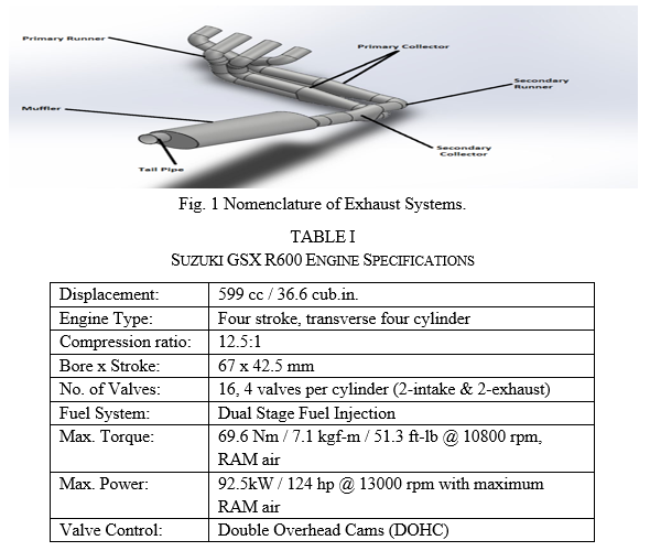
The exhaust manifold serves the purpose of diverting exhaust gases from all cylinders of the engine then releases them through a single opening. In order to characterize the flow and acoustic properties of an IC engine, it is necessary to understand the combustion process (4 stroke cycle). The main role of the exhaust system consists of removal of exhaust gases to create vacuum inside the combustion chamber which leads to induction of charge, regulation of engine noise, and improving engine performance concerning volumetric efficiency, power and torque etc. The components of the exhaust system are divided in two categories - main components and supporting components. The main components comprise of runners, collectors, muffler and tail pipe (Fig 1) whereas supporting components include flanges, springs and mountings.
II. PROJECT METHODOLOGY
The method used for this was the simulation study of a virtual engine model developed for the Suzuki GSX-R600 engine. Ojaswat Motorsports' experience from previous FSAE events were recalled to estimate the operating engine rpm range for the engine. Calculations were performed using mathematical equations in order to discover the diameters and lengths of the exhaust manifold based on the operating rpm ranges. We verified these results by making changes to the 1-D virtual GT-Suite engine as a result of these results. Through multiple iterations, the performance parameters were monitored, and the best result was selected. The final CAD geometry was developed according to the packaging constraints. ANSYS software was used to analyse the final CAD geometry for flow analysis. Various material properties were studied for the specific purpose of fabrication of the exhaust system.
III 1-D ENGINE SIMULATION
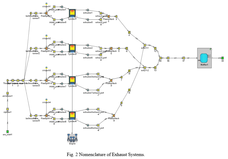
GT-SUITE is the leading engine and vehicle simulation tool used by engine makers and suppliers. This software is the industry-standard engine simulation tool. It is also used for ship and power-generation engines, small 2 and 4 stroke engines and racing engines (F1, NASCAR, IRL etc). The work examines the engine's power performance and component design as well as the major parameters involved in the design and development of race engines. The analysis was carried out using a 1-D simulation model constructed in GT-Suite. The most noticeable development we made using the GT-Suite was our exhaust system simulation accuracy.
IV. DESIGN OF EXHAUST SYSTEM
A. Geometry Selection
- The primary stage of designing the exhaust system begins with the selection of geometry, this selection is based on analysing the available packing space and design goals of the system. The other factors which are taken into account for the selection of geometry includes flow characteristics for the engine at high engine speeds and loss of power associated with it, effects on RPM bands which ultimately affects the peak torque and peak horsepower, variation in volumetric efficiency etc. Besides, other important parameters considered in the design phase were transmission losses of air pressure and sound attenuation ability of the particular geometry, compliance with the goal of overall weight reduction and manufacturing limitations involved during the fabrication process.
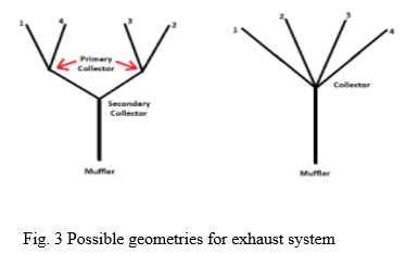
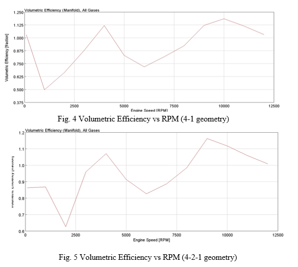
2. As 4-1 headers are generally found on performance cars since they have excellent characteristics at high RPM ranges, the exhaust system of a 4-1 combination was taken into consideration. They usually miss out at low RPM ranges but this loss in power is almost negligible and can be overcome, headers are designed so that all 4 exhaust pipes merge into one. Volumetric efficiency was selected as one of the criteria to be analysed to decide the geometry. Formula SAE competition holds a fuel efficiency event. Based on lap time simulations in MATLAB, the endurance engine speed range was found to be between 4000 and 10,000 rpm. The analysis was performed by performing 1-D engine simulations for both geometries to interpret the results, and comparing which one is better for enhancing engine performance. In the previous model car, a 4-1 geometry was used and it gave good results on the tracks. As a result, with some modifications, iterations were performed on 4-1 geometry. In addition to that, to check the previous exhaust system's performance, a 1-D engine simulation was conducted. However, it was noticed that the 4-1 geometry gave better results at higher RPM only. The team decided to give the 4-2-1 geometry a shot and it was observed that it has 5-10 % higher Volumetric Efficiency than 4-1 geometry. Moreover, the best results were obtained by performing CFD analysis on the iterations. After observing both geometry executions, GT-Suite was used to determine that the geometry of 4-1 produced satisfactory results when applied to higher revolutions. However, the 4-2-1 geometry gave superior results over the entire endurance range of revolutions. Keeping the competition in mind the team decided to select 4-2-1 as the final geometry.
3. On analysing both the geometries in terms of volumetric efficiency, manufacturing aspect & gross weight of the car, the 4-2-1 geometry offered better performance in comparison with the 4-1 geometry. Hence, a 4-2-1 type geometry was selected for the car's exhaust system.
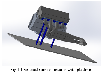
B. Collector
The key role of the collector is to combine exhaust pipe from all the 4 cylinders into a funnel type plenum collecting all exhaust gases entering from headers. As the firing order of the engine used is 1-2-4-3, cylinders runners 1-4 and 2-3 are paired together and then enter the collector. The idea of a collector is to allow one cylinder to benefit from the exhaust gas velocity of an adjacent cylinder. The boundary of increase in area or volume in the collector creates an impedance mismatch, making the incident wave reflect and transmit at this boundary. The reflected wave is used for tuning primary lengths, while the transmitted wave is put to use when tuning secondary headers. The cone shaped collector maintains air speed at the transition from the individual pipes to the collector. The pulses in each pipe will be maintained, but the pulses in the collector will be greatly reduced giving steady state airflow in the collector and tail pipe followed by the muffler reducing the back pressure of the exhaust system. In addition to this, the collector can also be used as a sound attenuating device (small muffler), if designed specifically.
C. Exhaust Runners
- Design Methodology: Runners are the integral part of the exhaust system, they provide flow passage for the exhaust gases to collector & muffler for attenuation of sound. The length of the pipe from where it exits the exhaust port to where both of the cylinder’s flows meet is known as the runner length. The design methodology used is - Initially, the packaging space constraints were studied for the exhaust system. This data after being studied, analyzed & based on past experience of the author, exhaust system geometry analysis was conducted. Due to the intricate nature of scavenging effects, literature reviews often provide equations that are appropriate for a particular engine assuming an ideal straight tailpipe. Analytical calculations were performed using the Smith equation (1972) and Bell equation (1988). With the help of GT-Suite, based on minimum & maximum packaging space available for the exhaust system, we performed different iterations to achieve an optimum runner length. This runner length allows the horsepower/torque curves to be changed by varying them. A shorter runner will produce more peak Horsepower, while the longer runner will shift the torque curve lower in the rpm band.
- Calculations: Two equations by Smith equation (1972) and Bell equation (1988) give estimates lengths from cylinder characteristics and expected engine speeds and are given by
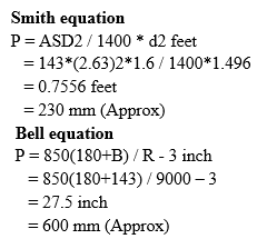
where P represents pipe length, A is exhaust open period in degrees, S is stroke length in inches, D is cylinder bore in inches, d is exhaust valve port diameter in inches, B is the degree of exhaust opens before BDC (bottom dead centre), and R is the target rpm.
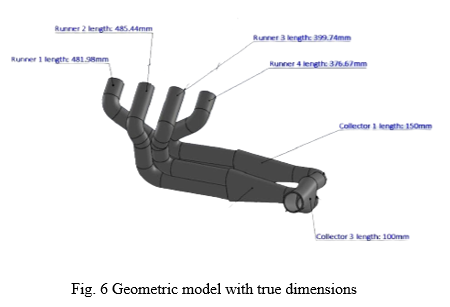
3. Results: The smith & bell equation results in pipe length estimates of 230 mm and 600 mm respectively. So, for better results equivalent length was taken as their average: 400 mm. With the GSX-R600 12000 RPM redline, and current gearing options it is estimated that the majority of competition will be run in the 4000 to 10,000 RPM range. This is helpful to know, as the runner length can be tuned to perform best within the specified range. Based on geometric iterations & available packaging space, optimized runner length dimensions were selected (Fig. 6)
For R1 - Runner length = 481.98 mm
For R2 - Runner length = 485.44 mm
For R3 - Runner length = 399.74 mm
For R4 - Runner length = 375.57 mm
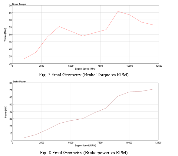
To investigate the effect of length variation, the primary length was varied from 300 to 500 mm, and volumetric efficiency, power and torque curves were plotted. Analysis of the volumetric efficiency showed a change of 5-10% in 4-2-1 geometry showing better results. Further, the graph of Torque vs RPM demonstrated 66.08 kW of torque at 9000 rpm, which was better than the 4-1 geometry. Additionally, a power of 70 kW was achieved at 12000 rpm.
An estimated 5% variance can be observed in torque and power curves if obtained through dyno testing. Variations are primarily caused by losses such as drive axle losses, drivetrain losses, and friction losses between the roller and tire. These losses are not taken into account during simulations. All these results led to the design of an exhaust system that used optimal runner lengths.
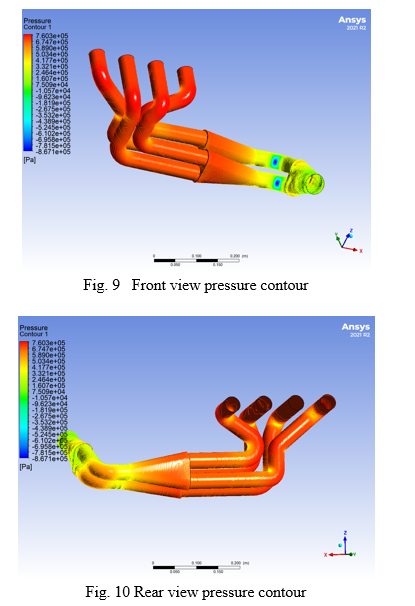
4. CFD: The exhaust system was subjected to a CFD analysis without considering the muffler in order to determine the proper flow of exhaust gases in the manifold. GT-Suite was used as a data acquisition tool for inlet boundary conditions, and atmospheric conditions were taken into consideration for exhaust outlet. The back pressure in an exhaust manifold is an important criterion for efficiency of the engine. According to the results of the pressure contours in Fig 9 and Fig 10, it appears that the exhaust gases created by the engine pass through an area with a low-pressure difference within the back pressure zone of the exhaust manifold.
D. Muffler
- A Muffler is a noise controlling device that is utilized to reduce the sound formed by the exhaust gases pushed out from an IC engine. According to the Formula SAE guide lines the aim is to design and build an exhaust system that will not exceed 103 dB and 110 dB at an idle speed and all supplementary speeds respectively. Selection of the muffler is based on the following factors: Sound to be attenuated, effect on engine performance, space availability, gross weight and cost. There are two types of mufflers - Reflective type muffler & Absorptive type muffler. A reflective muffler employs the process of destructive interference for noise reduction. These are designed in such a way that the sound waves cancel each other to some extent by themselves. Exhaust gases are forced to pass through a series of resonating and expansion chambers which results in reduction of noise at various frequencies. While the absorptive muffler is based on the reduction of sound energy by means of absorption. A sound absorbing material is used in this type of muffler in which the absorbed sound energy is converted into heat. The sound waves are passed through a perforated pipe which is enclosed by a sound absorbing material in a closed casing.
- In this thesis, on the theoretical basis of reflective sound cancellation, the decision was made to use a combination type muffler which uses both sound absorption as well as reflection principles. The designing methodology is based on testing and fabricating mufflers of different sizes, geometries and noise attenuating principles, with an increasing backpressure, till the noise level requirements are met, then the minimum backpressure required to meet the noise level requirements is found. Based on which the lightest and least volume consuming muffler is designed and fabricated. The testing setup will consist of the car, with the engine running on the same conditions for the test and the noise level measured with a dBC scale sound level meter. The design procedure goes like this:
A CAD model of the muffler is made.
It is simulated in ANSYS® Fluent, to get the backpressure at idle RPM and 9000 RPM.
It is then fabricated, weighed and then fixed to testing setup.
The noise level is measured at idle and peak RPM.
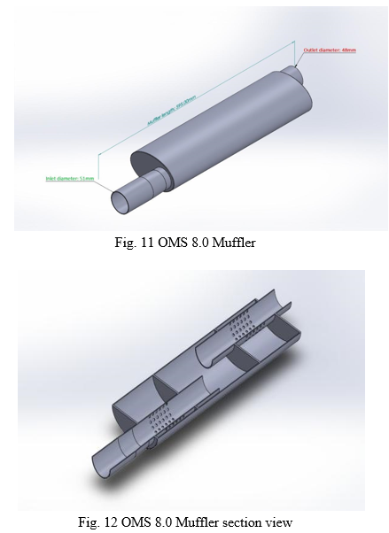
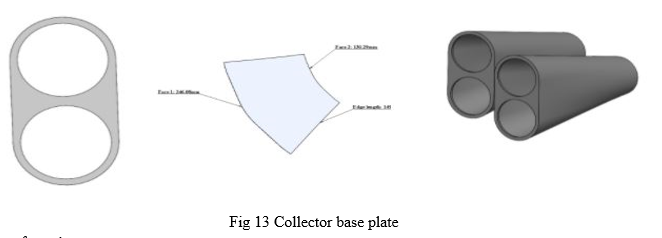
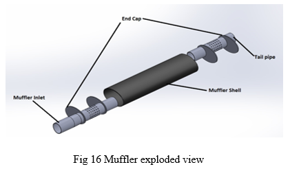
3. Geometrical Explanation: The muffler was designed oval shaped with major & minor diameters as 110 mm & 70 mm. The length of the muffler was 420 mm long having 3 chambers divided by 2 baffle plates of thickness 1.5 mm. The length & dia. of inlet as well as outlet pipes was 170 mm & 51 mm respectively. The pipes were centrally perforated over a length of 50 mm having 100 no. of holes of 3.5 mm dia covering 360° of the pipe. Solidworks & GEM-3D were used to design the muffler. Generally, glass wool was used as the sound absorptive material, while we used rockwool because of its high density & sound absorption properties. Rockwool has 1.0 noise reduction coefficient (NRC) which means it is nearly a perfect sound absorption material while glasswool has 0.8 NRC which makes it less compatible for sound absorption comparatively. Rockwool is less effective at low frequencies, but exhaust systems work at much higher frequencies. So, rockwool appears the best fit as an adoption material for OMS 8.0.
V. MATERIAL SELECTION
A. Exhaust Manifold Material
- Material selection is a very important part of engineering processes as far as the design of systems is concerned. Generally, an effective material selection process implies selecting materials with optimal costs & good performance that meets the component designed service life. For the exhaust system, we used GT-Suite to collect data about the temperature range of the exhaust system & it came out in the range of 490°C - 610°C. So, the selected material for manufacturing the exhaust system should be able to handle temperatures in this range. Also there are various other corrosion factors like high temperature oxidation, de-icing salt contamination and wet corrosion by condensates (mainly towards the tail pipe section).
TABLE II
Material characteristics for OMS 8.0 exhaust system components
|
Criteria |
Exhaust manifold |
Muffler |
Tail pipe |
|
Service temperature |
540-610°C |
270-350°C |
50°C-100°C |
|
Required properties |
-Resistance to high temperature -Thermal fatigue life -Oxidation resistance |
-Corrosion resistance -Oxidation resistance |
-Corrosion resistance -Oxidation resistance
|
2. After observing the properties (TABLE III), SS 304 was selected due to its cost effective, high strength and corrosive resistant properties. But performance wise titanium excels due to its stronger and lighter than steel characteristics. Aside from being extremely lightweight and strong, there is also a noticeable manufacturing problem with titanium. It is difficult to weld titanium because when exposed to the atmosphere, oxygen found in air can infiltrate & hence corrupt the weld. Also, the unavailability of SS 409 & difficult welding & bending of it compared to SS 304 makes the 304 stainless steel more effective & cost efficient. Moreover, SS 304 has more chromium & nickel proportions compared to 409 stainless steel making it more corrosion resistant. Hence, we decided to use 304 stainless steel for the manufacturing of the OMS 8.0 exhaust system.
TABLE III
Properties of Material taken into consideration
|
Material/Grade |
Density (kg/m3) |
Modulus of elasticity (GPa) |
Service temperature (°C) |
Coefficient of thermal expansion (µm/m-°C) |
||
|
0-100°C |
0-315°C |
0-538°C |
||||
|
Ti-6Al-4V (Grade 5)
|
4420 |
114 |
690 |
8.6 |
9.2 |
9.7 |
|
304 |
8000 |
193 |
|
17.2 |
17.8 |
18.4 |
|
409 |
7800 |
200 |
998 |
11.0 |
11.7 |
12.4 |
B. Absorbing material
- In general, soft, pliable, or porous materials (like cloths) serve as good acoustic insulators –absorbing most sound, whereas dense, hard, impenetrable materials (such as metals) reflect the most. Materials which we sorted for our sound absorption layer are: Rockwool, Glass wool and Steel wool
TABLE IV
Properties of Absorbing material
|
Properties |
Glass wool |
Rockwool |
Steel wool |
|
Density (kg/m3) |
10-100 |
80-150 |
50-160 |
|
Applicable Temperature range (°C) |
Up to 230 °C |
Up to 700 °C |
Up to 1000°C |
2. Rockwool can withstand temperatures of up to 700° C, while glass wool melts around 600° C. Rockwool is mostly preferred for high service temperatures because of its high insulation capacity compared to glass wool. So, rock wool was used as an absorption material for the muffler.
VI. MANUFACTURING OF EXHAUST MANIFOLD
A. General Manufacturing
Manufacturing is one of the most important engineering aspects. Selection of standard size raw material is the most favourable in terms of cost and availability. A properly planned manufacturing can neglect the errors while fabricating the exhaust manifold. The errors that can arise are shrinkage due to welding of pipes as the thickness of pipes are very less (1.5mm standard size), angular mismatch, orientation mismatch, irregular profile of pipes which lead to decrease or increase in diameter of exhaust runner which lead to improper flow of exhaust gases. To minimize all these errors, an exhaust manufacturing plan is developed on the basis of experience. Raw Material used for Exhaust manufacturing are SS 304 pipes dia 38mm (according to standard thickness of 1.5mm), SS 304 pipe Dia 51mm, SS 304 elbows (angles) of different arc length, SS 304 sheet cutout (2mm thickness), Aluminum Pipe ID 51mm, Aluminum sheet 2 mm thickness (assumption), Rockwool, Glasswool, Perforated sheet.
B. Collector Manufacturing
Exhaust manufacturing is started after placement of engine in chassis and location of fuel tank is fixed in the cockpit as the FSAE rules indicate that all the exhaust system components should be 50mm away from the fuel tank. Referring to the design a drawing should be prepared (prefer real dimensions) or E-drawing. Before starting manufacturing on car exhaust systems, the prerequisites are, Machining/Cutting of collector sheet (side-1) (Fig 11), Cutting layout of collectors (frustum shape), Rolling of collector cutout and welding with the collector sheet.
???????C. Runner Manufacturing
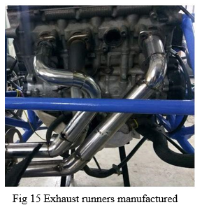
Considering the compact design of the exhaust manifold it is a major concern to maintain the geometrical accuracy, as the profile of bends should be perfectly aligned to the joining member. For observing the geometrical accuracy of the exhaust manifold, a mock manufacturing can be carried out using any other cost-effective material, such as PVC pipes, hardbound cardboard pipes, etc. As a result of the analysis of mock manufacturing, the team created E-drawings of individual runners for angle and length verification in 2D space. For maintaining the geometry in 3D, specially designed fixtures were prepared. These fixtures retain the components in their position after welding. The process of joining metals is carried out at high temperatures, which creates structural deformations due to the formation of internal stresses. Such deformations must be controlled to reduce the risk of failure (Fig 14). These fixtures are classified into two horizontal fixtures and vertical fixtures. The horizontal fixture is placed to maintain the distance between the adjacent runners, while the vertical fixtures are to guide the pipe to maintain the geometry.
???????D. Muffler Manufacturing
An oval shaped shell with a defined distance between baffle plates and perforated pipes was to be manufactured. A cutting operation was performed on the sheet of aluminium to create the chamber of the muffler. Bending operation was used to bend the oval shape of the chamber. An open end of the sheet was then welded to the completed end-chamber of the case, followed by welding a seam down its length. As shown in Fig. 16. To make the end cap, a sheet was holed with inlet and outlet diameters. Following that, the inlet and outlet pipes were perforated, and the baffle plates were also holed as well as the end caps. As a whole assembly of perforated pipes and baffle plates is being inserted into the chamber enclosure, welding beads are being applied on the adjacent corners of the open-end cap. A rigid mount will attach the muffler to the chassis, and a spring will connect the exhaust runner to the muffler.
VII. ACKNOWLEDGMENT
We express our deep sense of obligation and gratitude to our guide, Mr. Anand Patel, for his genuine guidance and continued encouragement throughout this work project. We are very grateful to him, as my honourable guide has given his valuable time to and shared his expert knowledge. We are grateful to the Faculty of Mechanical Engineering of C.S.P.I.T Charusat University- Changa for the permission to carry out the work of the project. We are also grateful to all the colleagues of Ojaswat Motorsports that have directly or indirectly helped me complete my work. We are also thankful to Dr. Mayur Sutharia, Dr. Vijay Chaudray (Mechanical Engineering HOD) and our Principal Dr. Y. P. Kosta for their support.
Conclusion
The final design includes some new features and aspects over the pre-existing design. For 4-cylinder engine (GSX-R600) a 4-2-1 geometry has been finalised as it shows an increase in performance by 5-10% in terms of volumetric efficiency with respect to previous years car. In order to validate the runner length, torque vs RPM and brake power vs RPM graphs have been studied. With the help of acoustics and exhaust scavenging theories exhaust manifold and muffler design has been performed. According to the working conditions of exhaust, different materials have been analysed and SS304 has been selected. Detailed manufacturing techniques were developed for different parts of the exhaust system in order to maintain the accuracy and geometrical correctness.
References
[1] S. M. Metev and V. P. Veiko, Laser Assisted Microtechnology, 2nd ed., R. M. Osgood, Jr., Ed. Berlin, Germany: Springer-Verlag, 1998. [2] J. Breckling, Ed., The Analysis of Directional Time Series: Applications to Wind Speed and Direction, ser. Lecture Notes in Statistics. Berlin, Germany: Springer, 1989, vol. 61. [3] S. Zhang, C. Zhu, J. K. O. Sin, and P. K. T. Mok, “A novel ultrathin elevated channel low-temperature poly-Si TFT,” IEEE Electron Device Lett., vol. 20, pp. 569–571, Nov. 1999. [4] M. Wegmuller, J. P. von der Weid, P. Oberson, and N. Gisin, “High resolution fiber distributed measurements with coherent OFDR,” in Proc. ECOC’00, 2000, paper 11.3.4, p. 109. [5] R. E. Sorace, V. S. Reinhardt, and S. A. Vaughn, “High-speed digital-to-RF converter,” U.S. Patent 5 668 842, Sept. 16, 1997. [6] (2002) The IEEE website. [Online]. Available: http://www.ieee.org/ [7] M. Shell. (2002) IEEEtran homepage on CTAN. [Online]. Available: http://www.ctan.org/tex-archive/macros/latex/contrib/supported/IEEEtran/ [8] FLEXChip Signal Processor (MC68175/D), Motorola, 1996. [9] “PDCA12-70 data sheet,” Opto Speed SA, Mezzovico, Switzerland. [10] A. Karnik, “Performance of TCP congestion control with rate feedback: TCP/ABR and rate adaptive TCP/IP,” M. Eng. thesis, Indian Institute of Science, Bangalore, India, Jan. 1999. [11] J. Padhye, V. Firoiu, and D. Towsley, “A stochastic model of TCP Reno congestion avoidance and control,” Univ. of Massachusetts, Amherst, MA, CMPSCI Tech. Rep. 99-02, 1999. [12] Wireless LAN Medium Access Control (MAC) and Physical Layer (PHY) Specification, IEEE Std. 802.11, 1997.
Copyright
Copyright © 2022 Hitesh Naranng, Keshav Sharma, Donil Mehta, Smit Sheth, Smit Bhanderi, Anand Patel. This is an open access article distributed under the Creative Commons Attribution License, which permits unrestricted use, distribution, and reproduction in any medium, provided the original work is properly cited.

Download Paper
Paper Id : IJRASET43985
Publish Date : 2022-06-08
ISSN : 2321-9653
Publisher Name : IJRASET
DOI Link : Click Here
 Submit Paper Online