

Ijraset Journal For Research in Applied Science and Engineering Technology
Design and Optimization of Crankshaft for 4-Stroke Single Cylinder Engine using Pro-E
Authors: Baragati Raghavendra Swamy, Sudhakar Kodi, Palukuri Veerendra
DOI Link: https://doi.org/10.22214/ijraset.2022.44182
Certificate: View Certificate
Abstract
The design of a crankshaft is of 4 stroke single cylinder engine. so that two revolution of crankshaft for each stroke. The peak pressure acting on the engine crankshaft is 63 bar. The crankshaft of the located model is designed using pro engineering with the accurate dimensions and material standards of located Honda crankshaft. Pro engineer is one of the best design software in design tools were we can easily design components based on it dimensions and analyzing it with accurate results. Crankshaft dynamic analysis is done by using mechanism. Dynamic analysis is used to find out the motion of the bodies with represents to applied loads with the time frame of crank angle. The crank angle is calculated with respect to seconds as it takes 0.008 sec for each stroke with to revolution. This value re calculated by using spread sheet. The results of the analysis indicate the forces diagram of given connections at different crank angle. The piston acceleration is calculated to find out the theoretical and experimental results values of graph shown in results.
Introduction
I. INTRODUCTION
Combustion engines can be classified in two groups, as being follows External combustion (EC) engines and Internal combustion(IC) engines.
A. External Combustion (EC) Engines
In these engines the substances which are used as working products are separated by a conducting wall. Different fluids are used for combustion such as air, fuel and combustion products. These combustion fluids do not contact at any stage in moving parts of the engine. External combustion engines include various types reciprocating and turbine of steam engines and various types’ air or other light gas of Stirling cycle engines.
B. Internal Combustion (IC) Engines
Internal combustion engines produce power by converting chemical energy of the fuel into heat energy. This produces the useful mechanical work by converting the heat energy. In the process of converting this thermal energy into mechanical work, which is performed by increase in pressure which generates forces piston to move with connecting by creating stroke in the cylinder. The fuel combustion occurs inside the cylinder so this process is called internal combustion.
The piston engine is known as internal combustion heat engine. it supply air fuel mixture in to the cylinder where it gets compressed and later burnt resulting the power. The internal combustion engine are reciprocating type engines which are either spark ignition (SI) or compression ignition (CI), where the compression engine are called as diesel engines.
C. Reciprocating Engines
- Two-stroke Engines: This type of two stroke engine where it expansion process the removal of burnt gases at end of each process of expansion and the induction of fresh gas mixture for next cycle. The piston starts at top dead centre (TDC) and it moves downwards in the power stroke and at the bottom of this stroke the exhaust value gets opened or uncovered and so exhaust gases blow down to the exhaust system and at the same time the inlet ports are opened for charging the fuel/air mixture in to case in SI engine and air alone in case of CI engines. Two stroke engine the expansion, power stroke in each cylinder takes place at every revolution of the crankshaft and the exhaust and changing process takes place simultaneously.
- Four stroke Engines: The four stroke engine cycle operation takes place in 4 cycles, where the principles partly used are piston, inlet value, exhaust value and the fuel injection nozzle or injector. The inlet value is on the left side and the exhaust value is on the right side.
- Induction 2.Compression 3. Power 4. Exhaust
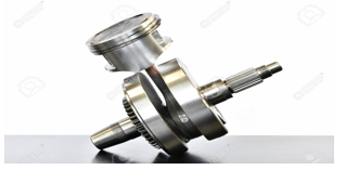
D. Crankshaft
Crankshaft converts the reciprocating motion into rotary motion. The reciprocating motion of the piston is transmitted to connecting rod which then convey to crankshaft. Crankshaft experiences variable forces acting on it. The tensile forces acting on the connecting rod and compressive force on the piston makes the reciprocating motion of the piston to rotary motion.
Crankshaft is made of alloy steel which is suitable as it generates high tensile. The crankshaft right end consists of a drilled flange which takes the flywheel and the power drive. The crankshaft left side to the belt pulley which results in cooling fan. The maximum engine speed and loads acting on the crankshaft determines the number of crankshaft bearings acting on it.
II. LITERATURE REVIEW
Zissimos P. Mourelaos conducted experiments about crankshaft system structure and dynamic analysis based on finite element method in 2001 vehicle design analysis lab, Warren. The experiments conducted on crankshaft response to the sets of loads applied. Crankshaft loading is due to the cylinder pressure acting and inertia due to piston and connecting rod. Zissimos analysed about the force and moment conditions and max pressure acting at different crank angle. The experiments were conducted on six cylinder engine.
From the output here in our project by designing the crankshaft on single cylinder engine in pro engineering software and analysing the response of forces acting on the piston with respect to crank angle and calculating the pressure with revalent to crank angle of honda motor single cylinder engine. But the project of the model design is four stroke engine were calculating the forces due two revolution of crank. The analysed were performed of Zissimos on V six engines have finite element mesh.(Zissimos P. Mourelaos, 2001).
The project output helps in analysing the graphs response of loads acting terms of pressure with respect to crank angle by comparing single cylinder to six cylinder engines. (Zissimos P. Mourelatos, 2001)
F.S.Silva university of Minho, Portugalconducted causes failure in crankshaft the investigated on failures on crankshaft life of 30000 kms the results conducted that the failure is caused due to the three types one is operating, mechanical and repairing failures by analysing these failures causes in design of crankshaft of the crankshaft can be useful by eliminating them.
F.S.Silva concluded that operating failures are due to lack of oil, not proper lubrication, mechanical failure are due to improper size of journal bearing and due to crankshaft vibrations and the repairing failures are due to not proper alignment of crankshaft, high roughness and high stress concentration. By analysing this topic helps project about the standards specification and compare that no mechanical failures occur due to the improper design of crankshaft size.(F.S. Silva, 2003).
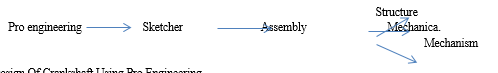
III. PRO-ENGINEERING
It is a computer aided design (CAD) program which develops model in computer. Pro engineer wildfire is based on parametric CAD program. Pro engineer is one of the best design software in design tools were we can easily design components based on it dimensions which is usually in three dimensions process the brief layout is that we need to design the component in sketch tool and developing the component different parts in part command and assembling them in assembly command and analyzing by mechanism..
Pro engineering is perfect option for the manufactures which provides easy applications and idea flexible engineering solutions. It can be used in all industries and consumer goods and engineering components. The finite element analysis of model can be done in pro-mechanica.
Design Of Crankshaft Using Pro Engineering
- Part Modelling: Pro-engineer wildfire 4 is used for design of model. The design of engine crankshaft is done by designing part of the different components and assembling of the part models by using their mechanism.
- Design Of Engine Crankshaft Model Having The Following Components In Pro Engineering
a. Connecting rod
b. Crank web left side
c. Crank web right side
d. Crankpin
e. Piston head
f. Piston rings
g. Gudgeon pin
h. Rod support
i. Circlip
j. Bearings
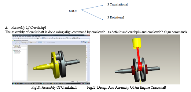
A. Assembly Of An Engine Crankshaft
Assembly is joining of all the components of different parts together to a single assembled component. The assembly of component is created by using align, mate component for automatic assembly and for mechanism the assembly of components by using different types of joints depending upon their mechanism.
Number of degree of freedom (dof) = number of independent parameters
DOF = completely unconstrained body
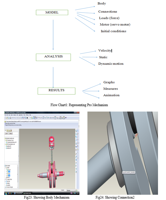
C. Pro Mechanism
The pro mechanism is design software which supports both the design and analysis of mechanism in pro engineering. The mechanisms are used to transfer the forces acting on the component to an output value by means of graph or results.
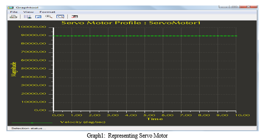
D. Motors
The motors defined as servo motor or force motor were the speed of the crankshaft is determined by selecting the type of motors and type of speed variable or constant speed can be defined by using the motor command. The motor are defined by selecting the geometry or by defining the connection axis. In design of engine crankshaft connection2 is selected for defining the motor.
- Motor Profile: The motors speed is selected in terms of deg/sec. the movement of the motor is at constant speed of 90000 The motors runs at constant speed where the speed of rotation in degrees per sec. so the motor runs at 15,000 rpm which is 250 rev per sec or 90000 degrees per sec. the magnitude value enter is 90000.
The magnitude can be defined as constant, cosine, from the table or user defined. Depending on the terms units of magnitude can be in representing by velocity, acceleration or position. The type of command can be created by selecting
Insert > servo motors
The graph represents the servo motor applied motor speed
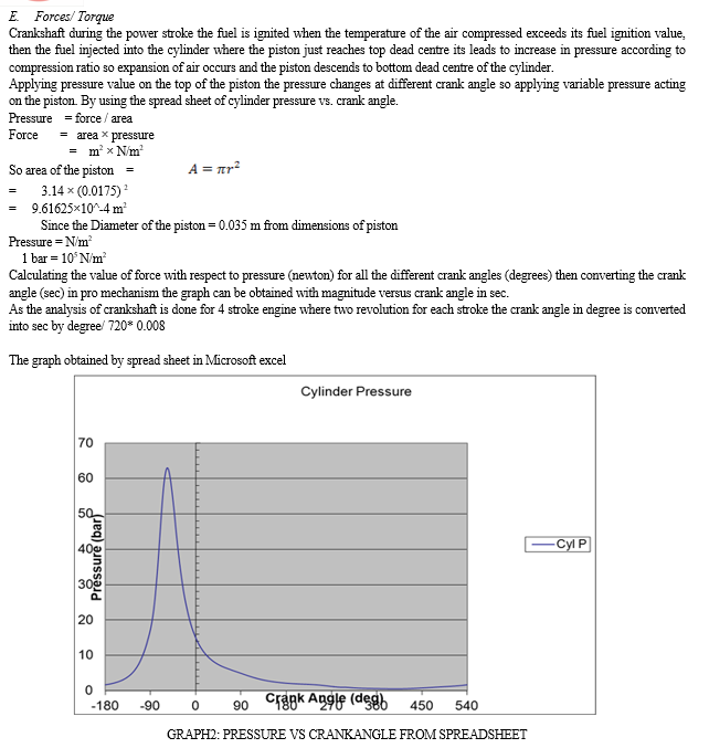
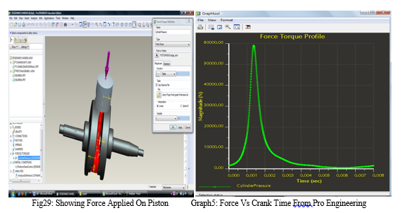
F. The Representing Graph Of Cylinder Pressure Can Be Done In Three Periods
- Ignition Period: It is that period where the spark is about to pass between the spark plug to start of rise of burning produced. The ignition period is between the spark starts ignition by passing through the electrode to produce a flame until the noticeable increase in pressure. Where the graphs start increase in pressure with I about compression pressure. It depends on the temp and pressure of the spark released and nature of the fuel used.
- Rapid Pressure Rise Period: The pressure curve can be represented where the rise in pressure just above the compression pressure to the pressure at peak point of the cylinder where the energy is released the graph increase at the peak point in this period.
- After Burning: The between where the pressure fall down, after burning period is the point after the peak pressure to the exhaust value opening takes place at power stroke .the graph gets decreasing slowing. In this period the burning of the flame is slow down so the pressure decreases. In this period the cylinder expanding takes place. The remaining mixture which is unburnt will burn at this period at a slow rate so the graph represents the pressure will decrease rapidly.
Applying forces to piston:
Forces > new > type of forces
Types of force/torque depending on the component
a. Point force
b. Body torque
c. Point to point force
IV. ANALYSIS
Types of analysis:
- Position
- Kinematic
- Dynamic
- Static
- Force balanced
- Position Analysis
The position analysis is used to position of components which are determined by initial configuration.
2. Static Analysis
The static analysis is done in case of finding the bodies in rest position such that no moving bodies which is in equilibrium position.
3. Kinematic Analysis
The kinematic analysis is done for driving loads which produces motion of mechanism
4. Dynamic Analysis
Dynamic analysis is used to find out the motion of the bodies with represents to applied loads where the time frame conditions exist.
Design of an engine crankshaft in pro engineering is done by using dynamic analysis. The piston is experiencing the cylindrical pressure due to the reciprocating motion, the piston is connecting to connecting rod by crankshaft, and by the rotation of crankshaft motion is generated so by calculating the force acting on the different connections by using dynamic analysis were the force is acting as a load and crankshaft rotation in engine is termed as motor speed.
- Selecting the type of analysis suitable for the component designed whether it is static or dynamic analysis.
- Selecting the duration of analysis
- Time frame of analysis
- Minimum time interval for analysis,
- The length and rate is the end time frame rate for defining the animation process
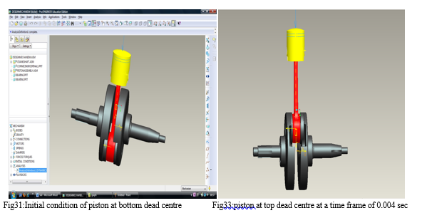
- Selecting initial condition in case of crankshaft design the initial condition of BDC is selected for initial configuration.
- The motors command it shows all the motor applied during the mechanism with starts and end configuration.
- Ext loads command it shows the applied loads during the mechanism in case of crankshaft the cylindrical pressure load with start and end notifications.
- Selecting the gravity option which indicates the enable of gravity considerations.
- Run command to start analysis the model
A. Running Analysis
B. Measures
Understand the mechanism on the bodies, analyzing the results for the applied motion. Acceleration measures:
Is measure is used for measuring the acceleration with to force acting on the moving body. For design of engine crankshaft the acceleration of piston at piston top head with respect to force can be calculated.
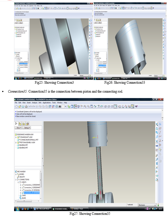
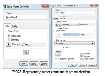
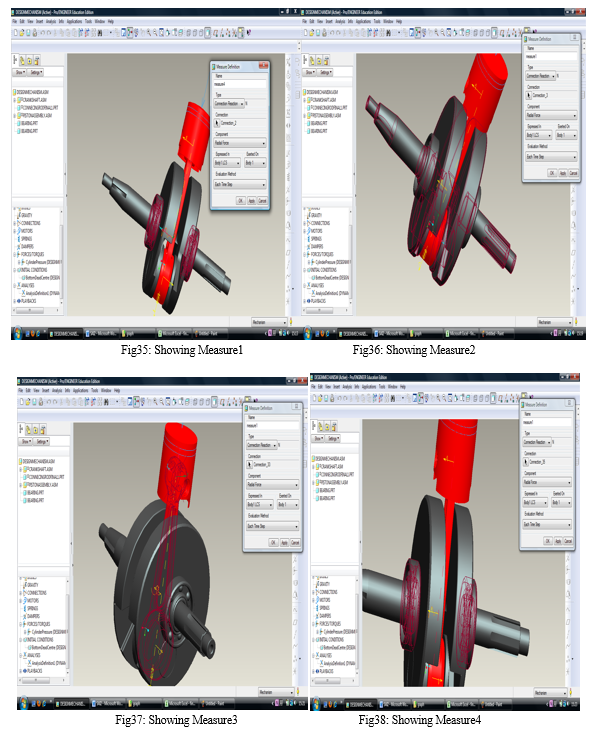
Connection reaction:
Connection reaction measure evaluates the load generated at a connection with respect to forces applied externally. We can measure the forces at different point of connection by using connection reaction.
C. Measures Obtained By Different Connection
VI. FURTHER RESEARCH
- By designing the piston of latest standards which are used in motor racing bikes we can understand and analysis more optimistic measures.
- By increasing the design size of crankshaft which is of single cylinder to multi cylinder engine.
- We can analysis the maximum forces can be applied such that find out the breaking point by using S-N curve applications.
- By using the latest material used in design we can understand more reliable. We can analyse the design in ansys so that we can understand by compare it.
Conclusion
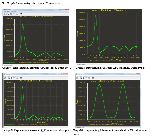
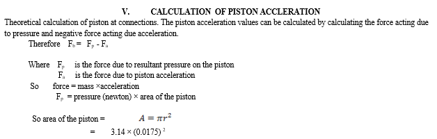
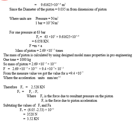
As of measure graphs from the practical design of engine crankshaft in pro engineering are similar to the theoretical graph obtained from the spread sheet. Design of engine crankshaft is analyzed by using the standard forces acting on the piston of four stroke engine. By using dynamic analysis measure at different connection we obtained the forces acting on the connections with represent the movement of crank angle. The peak pressure obtained for an engine crankshaft at 63 bar at a -53.6 deg of crank angle from the spread sheet. By the dynamic analysis of engine crankshaft in pro engineering we obtained. Here the pressure doesn’t go negative as we calculated the absolute pressure in turns of atmospheric pressure. We should minus 1 bar for each of the value to obtain the extract spread sheet of negative value. 1) At Connection2: The peak force of 60000N at 0.0015 sec of crank angle from the graph in pro engineering and in dynamic analysis we obtained force value 3825.11 were the graph show in form. The force is max at 0.0015 sec and decrease at the end of time frame of 0.008 2) At Connection3: The peak force of 58000N at 0.0015 sec of crank angle from the graph in pro engineering the graph obtained is similar to force and time graph in spread sheet to pro engineering as a form. From the dynamic analysis definition measure results we obtained a value of 10596.6N 3) At Connection33: The peak force of 60000N at 0.0015 sec of crank angle from the graph in pro engineering from the dynamic analysis run process we obtained a value of 1382.78. 4) At Connection 35: The peak force of 14000N at 0.0015 sec of crank angle we obtained from the graph. It trend to decrease gradually down after it peak the peak point. The dynamic analysis shows the value of 0.21535. 5) At Piston Acceleration: By theoretical calculating the acceleration of piston with respect to pressure acting on it we can calculated the value of Fb = Fp - Fa which is 3520 N for the peak pressure of 63 bar.
References
[1] Rowland S. Benson, N.D. Whitehouse., Internal combustion engines, Volume1, Robert Maxwell M.C. [2] Brain E. Milton., Thermo dynamics combustion and engines, Chapman& hall. [3] Gordon P. Blair., Design and simulation of two stroke engines. [4] R.W. Bent., Motor vehicle technology, Part II, London sir Isaac Pitman & sons ltd. [5] Kuang - Hua Chang., Pro/Mechanica motion: Mechanism Design and Analysis, Release 2001,Schroff Development Corporation. [6] John B. Heywood., the Two Stroke cycle Engine, Society of automotive engineers, Inc. [7] The Design and Development of small internal combustion engines, papers, ImechE conference Publications. [8] Heinz Heisler., Vehicle and Engine Technology, second edition, Arnold Publishers. [9] Automotive Handbook. 7th Edition, Bentley Publishers. [10] Arthur W. Judge., Modern Smaller Diesel Engines, Volume7, Motor manuals [11] Getting stated with Pro/Engineer wildfire, April 2003, parametric technology corporation. [12] Shigley, Joseph E., Mechanical Engineering Design,3rd edition,1977McGraw-Hill. [13] Dave Cheshire., Dynamic Mechanism design tutorials, PTC [14] Apostolos Papanikolaou., Holistic Ship Design Optimization, Article, National Technical University of Athens, Greece. [15] Ford Motor company, how vehicles work: An Introduction to Automotive Technology, 1997, Ford motor publishers. [16] Roger Too good., Pro engineer Wildfire 4.0 tutorial, 2008, Schroff development publisher. [17] Taylor, Charles Fayette., The internal combustion engine in theory and practice, volume2, M.I.T. Press.
Copyright
Copyright © 2022 Baragati Raghavendra Swamy, Sudhakar Kodi, Palukuri Veerendra. This is an open access article distributed under the Creative Commons Attribution License, which permits unrestricted use, distribution, and reproduction in any medium, provided the original work is properly cited.

Download Paper
Paper Id : IJRASET44182
Publish Date : 2022-06-13
ISSN : 2321-9653
Publisher Name : IJRASET
DOI Link : Click Here
 Submit Paper Online