

Ijraset Journal For Research in Applied Science and Engineering Technology
Design of Pressure Vessel Using Computational Techniques
Authors: Bhavik Chavda, Rupak Shukla, Harshit Tiwari, Ashutosh Pandey, Yusuf Rehman
DOI Link: https://doi.org/10.22214/ijraset.2022.41116
Certificate: View Certificate
Abstract
This paper discusses some of the recent advances in determining the stress concentration factor in pressure vessels at openings, stress analysis of various types of end connections, and stress minimization by optimizing the location and angle of the nozzle on the shell and head. The area of stress concentration analysis in pressure vessels is gaining popularity, according to the literature. The goal of this study is to look at the stress concentrations that occur at the openings of pressure vessels and how to mitigate their effects. The ASME pressure vessel code governs the design of pressure vessels. The code specifies the thickness and stress of fundamental components; it is up to the designer to determine stress due to other loadings using an appropriate analytical approach. Recent and previous developments, theories for stress concentration estimate, and the possibilities for future investigations are all discussed in this study. We\'ll also use data analysis software like Solidworks to computationally assess our design. Also, technologies like Excel were considered for creating our design\'s data sheet, and they were coupled with Solidworks software for a speedy outcome. This strategy will not only save time but will also save money if used on a large basis. The project\'s main goals and objectives are as follows: Design the pressure vessel following the ASME (American Society of Mechanical Engineers) code. Create a Solidworks 3D model of a pressure vessel. Using Solidworks software, analyze the stiffness and strength of pressure vessel material and design. To improve the facility, staff, and public safety. To use simulation tools to check the design\'s accuracy. To ensure computation repeatability by using EXCEL as the design calculation method. To make all design methods more efficient in terms of time. To enhance public and personal security.
Introduction
I. INTRODUCTION
A process in engineering is a collection of interconnected actions that, when combined, change inputs into a certain output. These jobs can be performed by humans, nature, or robots using a variety of resources; an engineering process must be examined in the context of the agents doing the tasks as well as the resource properties. Systems engineering normative papers, as well as those related to Maturity Models, are often built on processes, engineering procedures and the Capability Maturity Model Integration (CMMI) institutionalization and improvement approach. Constraints placed on the tasks and resources needed to complete the project and are required to complete the tasks listed. Process manufacturing is a branch of manufacturing that deals with formulas and production recipes, as opposed to discrete manufacturing, which deals with discrete units, bills of materials, and component assembly. Food, beverage, chemical, pharmaceutical, nutraceutical, consumer packaged products, cannabis, and biotechnology businesses all use process manufacturing. Ingredients, not parts, formulas, not bills of materials, and bulk materials, not individual units, are important in process manufacturing. Despite the fact that there is inevitably cross-over between the two manufacturing branches, the major contents of the end product are the same. Manufacturing systems can generally be classed as one or the other based on the product and the majority of the resource intensity of the production process. A bottle of juice, for example, is a discrete thing, although juice is processed made. Although the plastic used in injection moulding is process produced, the components it shapes are typically separate and require additional assembly.
A. Types of Process Equipment used in industries
- Pumps
- Filters
- Valves
- Vessel and Tanks
- Heat Exchangers
Based on the reliability and feasibility, we chose to design Pressure Vessel (Vessel and Tanks) and perform the analysis of our project using ASME codes, PV Elite, Solidworks and Ansys computational software.
B. Pressure Vessel
A pressure vessel is a container that is designed to hold gases or liquids at a pressure higher than atmospheric pressure. The size of the vessel, the contents, the operating pressure, mass limits, and the number of items required will all influence the construction methods and materials used. Maximum safe operating pressure and temperature, safety factor, corrosion allowance, and minimum design temperature are all factors to consider when designing (for brittle fracture). Nondestructive testing, such as ultrasonic testing, radiography, and pressure tests, are used to evaluate the construction. Water is commonly used in hydrostatic pressure tests, whereas air or another gas is used in pneumatic pressure tests. Hydrostatic testing is favored since it is a safer procedure because if a fracture occurs during the test, substantially less energy is produced (water does not greatly increase its volume when rapid depressurization occurs, unlike gases, which expand explosively). Representatives are frequently seen in mass or batch production products. If the system's overall safety is sufficiently improved, pressure relief devices may be installed. Most countries require vessels of a given size and pressure to be built according to a set of rules. The ASME Boiler and Pressure Vessel Code is the code used in the United States (BPVC). The Pressure Equipment Directive is the code in Europe. The majority of the information on this page is only valid in ASME. Each vessel has a nameplate with pertinent information about the vessel, such as maximum allowable working pressure, maximum temperature, minimum design metal temperature, what company manufactured it, the date, its registration number (through the National Board), and American Society of Mechanical Engineers.
II. LITERATURE REVIEW
In thus section research papers are discussed related to the present work.
Henry H. Bednar (1986), has explained that when the forces applied to a vessel or its structural attachments are referred to as loads and in any mechanical design, the first requirement in vessel design is determine the actual values of the loads and the condition to which the vessel will be subjected in operation. These are also determined on the past experience, design codes, calculations, or testing. They also explained that a design engineer should determine conditions and all pertaining data as thoroughly and accurately and be conservative. The author also studied that Finite Element Analysis (FEA) is the most important numerical method. The reason is that FEA has gaining predominance in the computer process because the method can be formalized in a standard procedure that does not require any engineering decisions and is eminently suitable for computer programming.
Eugene F. Megyesy (2001), has explained about the stresses and different types of pressure under pressure vessels when pressure vessels are subjected to various loadings, which exerts stresses of different intensities in the vessel components. The category and intensity of stresses are the function of the nature of loadings, geometry and construction of the vessel components. When a vessel under external pressure, when other forces are not factors, designed must be resist the circumferential buckling. The code will help to provide the method of design to meet the required outcomes. The author also explained that the code symbol should be applied and vessel shall be designed and stamped with maximum allowable external working pressure. They recommended that a suitable margin is provided when establishing the maximum allowable external pressure to allow for pressure variation in service.
David Heckman (1998), tested contact elements to determine their usefulness in modelling the interaction between pressure vessel cylinder walls and end caps. When they modeled correctly, contact elements proved to be useful, but in this case the operator also to be able to interpret the results properly. Problems such as local stress risers, unrealistic displacements such data become extremely important in this kind of analysis. This highlights the importance of finite element analysis (FEA). The Professor also highlighted that the analyst should also able to approximate the solution using hand calculation in order to verify the solution.
B. S. Thakkar and S. A. Thakkar, did a case study and put efforts to design the pressure vessel using ASME code & standards to legalize the design. The performance of a pressure vessel under pressure can be determined by conducting a series of tests to the relevant ASME standard. Pressure vessel components are selected on the basis of available ASME standard and the manufactures also follow the ASME standard while manufacturing the components so that leaves designer free from designing the components. This aspect of design greatly reduces the development time of new pressure vessel, it also allows the designer to keep free from multiple prototypes for pressure vessel before finalizing the design, here standard part is used so it reduces time for replacement so less overall cost.
Somnath Chattopadhyay, has explained that pressure vessels often have a combination of high pressure together with high temperature, and in some cases flammable fluids or highly radioactive materials. This can occur to an hazards situation, so author explained that the rules for design, fabrication and inspection of pressure vessels are provided by codes that have been developed by industry and government. In various codes all have established rules of safety governing design, fabrication and inspection of boilers, pressure vessels and nuclear components. These codes are intended to provide reasonable protection of life and property and also provide for margin for deterioration in service.
In addition, there is a continuous attempt to understand all failure modes, and provide rational margins of safety against each type of failure. The author also concluded about pressure vessel by using computational techniques. In 1960s the use of components began to make an impact on design and analysis of pressure vessels. The rapid development of finite element software has remarkably impacted the detailed design of pressure vessel components. These developments along continuing increase in computing speed and storage capacity of the computer have really made the design process extremely quick and at the same time have led to very accurate design assessment. Initially the early to mid-1970s, detailed finite element analysis were generally performed for confirmatory analysis. The three-dimensional finite element analysis programs using solid elements are rapidly replacing plate, shell, and two-dimensional programs for routine structural design analysis of pressure vessels. In additions the concepts of computer-aided design (CAD) and computer-aided manufacturing (CAM) are being integrated.
S.J Niranjana, designed and explained that a pressure vessel is a device which has a pressure difference inside it by atmospheric pressure. As high operating pressures are a danger, utmost care should be taken while designing the pressure vessels. Any mechanical structure fails if there are stresses induced in them. The pressure vessel life under cyclic load is related to the number of cycles it is exposed to and to the intensity of the stress. The pressure vessel is assumed to be a thin cylinder, and therefore the analysis follows the thin cylinder formulae. The modeling was done on a modeling software, and a finite element analysis was carried out to highlight the various points of stress concentration. The finite element analysis-based workbench is used for analyzing pressure vessel components. It discusses modeling methods for various parameters in a cracked pressure vessel. It also gives few rules for performing analysis using fem like starting with a simple design and using, closed-form solutions for analysis.
R. Rustam, studied the effectiveness of FEA in the design and analysis of horizontal pressure vessels with and without expansion joints. It was concluded that the FEA tool was useful to design and analyze such components. The FEA results were also found to be in good agreement with mathematical model results. After doing an extensive literature survey it is found that vessels of different shapes and dimensions were designed and analyzed using a dedicated analysis software’s. Thermal and structural loads were considered as the boundary conditions for the same. Materials used in the actual pressure vessel are considered as input parameter. From the available literature it is evident that comparative study of structural performance of pressure vessel of different engineering materials has not been studied extensively.
Literature also suggests that stress analysis in thin-walled pressure vessels has not been validated. Such designs are light weight and compact and useful for small scale industrial plants. Very few studies have focused on the failure study of pressure vessel structures and it is an important factor for the selection of material in the fabrication of such critical components. This study focusses on the failure analysis of different engineering alloys such as stainless steel, carbon steel and titanium alloy used in structural, high strength applications involving dynamic pressure situations. The modelled pressure vessel is subjected to varying pressures keeping in mind the dynamic pressure variations expected in such vessels and their structural performance when subjected to different internal pressure values.
Abdolreza Toudehdehghan And Tan Wai Hong, explained that the design of a vessel needs to achieve a balance between the safety as well as economics. It was concluded that to accomplish this task, it requires the understanding of parameters affecting the pressure vessel due to varying loads, pressure and thickness. ASME code requires the pressure vessel to be designed based on the most severe conditions that the vessel is subjected to, including during the start-up, normal operation, possible deviations, and shut down.
M. A. Khattak, A. Mukhtar, A. F. Rafique and N. Zareen, explained that the design of pressure vessels safety, is the primary consideration, especially for nuclear reactor pressure vessels, due the potential impact of a possible severe accident. In general, however, the design is a compromise between consideration of economics and safety. The design factor used in the ASME Boiler and Pressure Vessel Code is intended to account for unknown factors associated with the design and construction of the equipment. The design formulas and the stress analysis methods are generally approximate and have built-in assumptions. Typically, it is assumed that the material is homogeneous and isotropic.
Matt Weber, explained the simulation and impacts on an object due to real-world loading circumstances were investigated. Computer simulation is a sort of simulation in which Cad Models are used to represent real objects, and varied load conditions are applied to the model to examine real-world impacts. We apply loads to a restricted model under predetermined environmental conditions in Solidworks Simulation and examine the results. Static analysis, in which loads are given to a body, the body deforms, and the effects of the loads are transferred throughout the body, was also discussed by the author. The body generates internal forces and reactions at the supports to balance the applied external loads in order to absorb the effect of loads. Internal forces and reactions produce strain and stress in the body.
Radostina V. Petrova, the principle of the FEM was explained, as well as the meshing of the solid model. The goal of the FEM is to slice the solid body into many small, simple-shaped cells that precisely mimic the body's form. Finite elements (FEs) or simply elements are the names given to these microscopic cells. They communicate with one another at nodes. Meshing is the process of converting a solid body model into a FE model, and it is a crucial stage in the FE workflow. It allows a complex engineering challenge to be replaced by a series of smaller bonded problems that must all be solved at the same time. The software generates a set of algebraic equations on its own, then connects them to construct a single sparse matrix equation.
III. AIMS AND OBJECTIVES
A. Whatever dimensions of the Pressure Vessel they have been computed using ASME codes have there been utilized to form visual understanding.
B. This 3D model is designed for safe working of the Pressure Vessel.
C. It will increase Repeatability.
D. It will increase Reproducibility.
E. This method will be Time Efficient.
F. It can be used for slightly different configuration of vessels for different components.
G. Also, we will use data sheet in solid works which will give the quick calculative results.
H. Use of excel data sheet in industries will save time and also save cost of the worker which will be used in design of vessels in conventional way.
IV. METHODOLOGY
A. Research Methodology
This project is conducted accordingly till the completion of the project in which desired results are obtained as shown below.
- Start
- Select and define research topic
- Prepare and evaluate research plan
- Literature review
- Identify the design parameters for pressure vessel design
- Study and list down the equations involved for design from ASME
- Implement the algorithm based on the design parameters and equations accordingly
- Designing in Solidworks
- Report writing
- End
B. Tools
This project will require the following tools to carry out the project:
- Microsoft Excel: MS Excel is used to calculate the given parameters of the pressure vessel and also with editable format.
- Solidworks 2021: Solidworks is used specifically to design support system for the pressure vessel design based on the suitable algorithm along with equations for pressure vessel design.
V. DESIGN AND CALCULATION
A. Design Of Shell
|
Material: |
SA 516 GR 70 N |
||||||
|
DESIGN CONDITIONS |
|||||||
|
Design Code |
|||||||
|
PARAMETER |
VALUE |
UNITS |
ABREVATION |
||||
|
Internal Design Pressure |
3.5 |
kg /cm2(g) |
P |
||||
|
Design Temperature |
95 |
oC |
T |
||||
|
Min. Design Metal Temperature |
12.5 |
oC |
MDMT |
||||
|
Max. Allowable Working Pressure |
3.5 |
kg / cm2(g) |
MAWP |
||||
|
Allowable stress |
485 |
Mpa |
S |
||||
|
Corrosion Allowance |
3 |
mm |
C. A |
||||
|
Under Tolerance Allowance |
UTP |
||||||
|
Joint efficiency |
0.85 |
E |
|||||
|
Shell Diameter (Internal) |
2100 |
mm |
id |
||||
|
Shell Radius (Internal) |
1050 |
mm |
Ri |
||||
|
Length of the shell |
6000 |
mm |
L |
||||
|
Specific gravity of shell material |
7.85 |
sp.gr. |
|||||
|
CALCULATING REQUIRED THICKNESS FOR DESIGN PRESSURE |
|
||||||
|
|
|||||||
|
Along circumferential |
|
||||||
|
|
|||||||
|
tb = |
P x Ri |
+ C. A |
|
||||
|
S x E - 0.6 x P |
|
||||||
|
|
|||||||
|
|
|||||||
|
tb= |
12 |
mm |
|
||||
|
|
|||||||
|
DISH END |
|
||||||
|
|
|||||||
|
tb= |
P x Di |
+ C. A |
|
||||
|
2SE - 0.2P |
|
||||||
|
|
|||||||
|
tb= |
12 |
mm |
|
||||
B. Weight Calculations
|
Shell: |
|||
|
Ws = π * D * L * t * sp.gr. in kg |
|||
|
where, |
|||
|
D: Mean shell diameter |
2.112 |
m |
|
|
L: Length of the shell |
6 |
m |
|
|
t: Thickness of the shell |
0.012 |
m |
|
|
sp.gr.: Specific gravity of shell material |
7850 |
kg/m3 |
|
|
hence, |
Ws = |
3735.70 |
kg |
|
Dished ends: |
|||
|
Wd = 1.084 * D2 * t * sp.gr. * 2 in kg |
|||
|
hence, |
Wd = |
907.90 |
kg |
|
Manhole & cover: |
205.00 |
kg |
|
|
Nozzles: |
150.00 |
kg |
|
|
Internals: |
200.00 |
kg |
|
|
Externals: |
100.00 |
kg |
|
|
Saddles: |
500.00 |
kg |
|
|
Volume: (Full) |
49.50 |
m3 |
|
|
Volume: (Operating - max. liquid level 1.8m from bottom) |
45.60 |
m3 |
|
|
Specific gravity of process fluid |
0.980 |
|
|
|
Insulation: |
|||
|
Wi = π * D * L * t * sp.gr. + 1.084 * D2 * t * sp.gr. * 2 in kg |
|||
|
were, |
|||
|
D: Mean shell diameter Including insulation |
2.137 |
m |
|
|
L: Length of the shell |
6 |
m |
|
|
t: Thickness of the insulation |
0.025 |
m |
|
|
sp.gr.: Specific gravity of shell material |
7850 |
kg/m3 |
|
|
hence, |
Wi = |
9719.70 |
kg |
|
Fabricated weight: |
5798.60 |
kg |
|
|
after adding 10% extra |
6378.46 |
kg |
|
|
say after rounding off |
1400 |
kg |
|
|
Site erected weight : |
16098.16 |
kg |
|
|
say after rounding off |
1400 |
kg |
|
|
Operating weight (max.) |
46088 |
kg |
|
|
say after rounding off |
46500 |
kg |
|
|
Weight full of water: |
50900 |
kg |
|
|
say after rounding off |
50900 |
kg |
|
|
Maximum Weight: |
50900 |
kg |
|
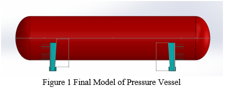
C. 3D Model of Pressure Vessel
In 3D computer graphics, 3D modelling is the process of developing a mathematical coordinate-based representation of any surface of an object (inanimate or living) in three dimensions via specialized software by manipulating edges, vertices, and polygons in a simulated 3D space.
Three-dimensional (3D) models represent a physical body using a collection of points in 3D space, connected by various geometric entities such as triangles, lines, curved surfaces, etc. Being a collection of data (points and other information), 3D models can be created manually, algorithmically (procedural modelling), or by scanning. Their surfaces may be further defined with texture mapping.
Almost all 3D models can be divided into two categories:
- Solid: These models define the volume of the object they represent (like a rock). Solid models are mostly used for engineering and medical simulations, and are usually built with constructive solid geometry.
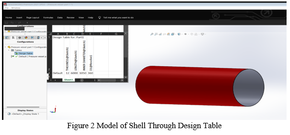
- Shell or boundary: These models represent the surface, i.e. the boundary of the object, not its volume (like an infinitesimally thin eggshell). Almost all visual models used in games and film are shell models.
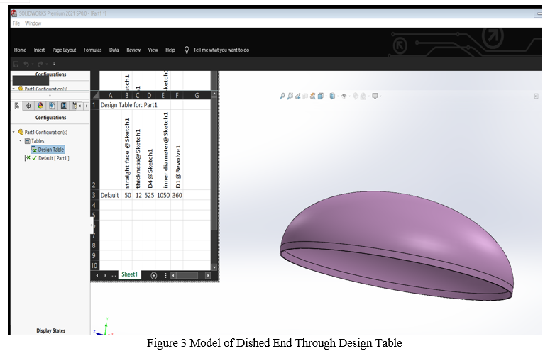
D. Introduction To Design Table
A design table allows you to build multiple configurations of parts or assemblies by specifying parameters in an embedded Microsoft Excel worksheet. The design table is saved in the model document and is not linked to the original Excel file.
Inserting a Design Table
- You can select create in the Design Table Property Manager to insert a design table.
- To have the SOLIDWORKS software insert a design table.
- In a part or assembly document, click Design Table (Tools toolbar) or Insert > Tables > Design Table.
- In the Property Manager, under Source, select Auto-create.
- Set the Edit Control settings and Options, as desired.
- Click Depending on the settings you selected, a dialog box may appear that asks which dimensions or parameters you want to add.
- An embedded worksheet appears in the window, and the SOLIDWORKS toolbars are replaced with Excel toolbars.
- Cell A1 identifies the worksheet as Design Table for: model name.
- Click anywhere outside of the worksheet (but in the graphics area) to close the design table.
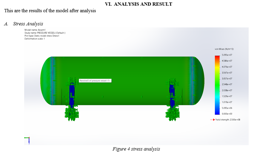
The above figure shows the result of stress analysis performed on Soliworks Simulation.
The value is less than the maximum value. i.e., 5.095 x 10⁷ (N/m2) < 2.5 x 10⁸ (N/m2
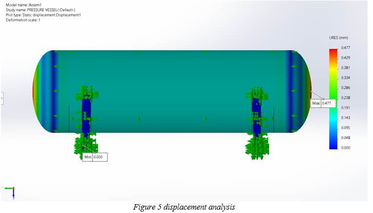
B. Displacement Analysis
As a result, using the List Result Force option, the force required to produce the prescribed displacement can be backed out, and the resulting stresses may be calculated.
If you ever need to apply both a translation and a rotation, you can use the Remote Load/Mass option found under the External Loads pulldown.
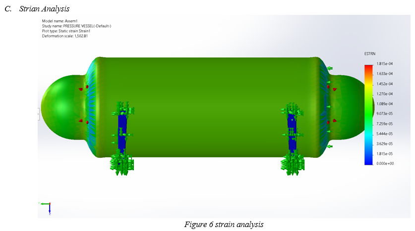
The above figure shows the result of strain analysis performed on solidworks simulation.
D. Result Obtained
|
Test |
Max. Design value |
Obtain value |
Remarks |
|
Displacement |
2mm |
0.477mm |
Safe |
|
Stress |
2.500 x 10⁸ N/m2 |
5.095 x 10⁷ N/m2 |
Safe |
The following values are true and considerably under limit as analysis is concerned.
Therefore, we conclude that the overall design of our SA 516 Gr. 70 N Pressure Vessel is Safe.
VII. FUTURE SCOPE
A. This can be used with Structured Query Language (SQL).
B. It can be used with web development software like java, python, etc.
C. It can be used in FEA software like Ansys, Matlab.
D. Further verification of pressure vessel can be done using PV Elite software.
E. It can also be used for the fluid which is in dynamics.
F. This technique can be introduced in academic syllabus.
G. It can be used using smartphones or tablet pc.
VIII. ACKNOWLEDGMENT
This work was supported by Department of Mechanical Engineering of Theem College of Engineering, Boisar, Maharashtra. And we are also thankful to S. Tech. Consultancy Services, Mumbai for Providing an opportunity and availability of an on-going Industrial Project on Pressure Vessel as a Final Year Project.
Conclusion
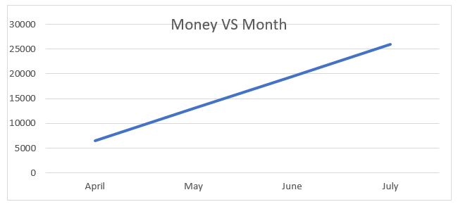
1) In this topic the analysis of pressure vessel is done using ASME codes and Solidworks simulation software. 2) Whatever dimensions have been obtained is useful to design and compute a horizontal pressure vessel. 3) This topic is introduced for small to medium scaled industry which will result in saving capital. 4) In the above given graph, we can see that how the slope increases. The x-axis is represented by month and y-axis is represented by amount in rupees which is to be spent for designing a pressure vessel. 5) In today’s scenario, we assumed the daily wage of the draftsman to be 250 rupees. If we multiply the amount by 26 working days, we would get an amount of rupees 6,500. Which will save 78,000 rupees of the industry yearly. 6) Thus, by introducing this idea in the industry, not only we can save the capital but also can have a good interchangeability, good repeatability, feasibility of the project. 7) This project is looking forward to help industry with user friendly software.
References
[1] B.S.Thakkar, S. (2012). Design of Pressure Vessel using ASME Code, Section 8 Division 1. International Journal of Advanced Engineering Research and Studies, IJAERS/Vol. 1/ Issue 2, 228-234. [2] Bednar, H. H. (1986). Pressure Vessel Design Handbook. Krieger. [3] Chattopadhyay, S. (2004). Pressure Vessel Design and Practice. Taylor % Francis Group, LLC. [4] COMPANY, A. (2017). ASME Boiler and Pressure Vessel Code an International Code. New York. [5] Heckman, D. (1998). Finite Element Analysis of Pressure Vessel. 1-7. [6] Hong, A. T. (2019). A Critical Review and Analysis of Pressure Vessel Structures. International Postgraduate Conference on Mechanical enginering, 7-8. [7] M. A. Khattak, A. M. (2016). Reactor Pressure Vessel Design and Fabrication . Journal of Advanced Research in Applied Mechanics, 1-6. [8] Megyesy, E. F. (1972). Pressure Vessel Handbook. Pressure Vessel Publising,inc. [9] Moss, D. R. (2004). Pressure Vessel Design Manual. USA: Gulf Proffesional. [10] Petrova, R. V. (2015). Introduction to Static Analysis Using Solidworks Simulation. London: CRC Press . [11] Rustam, R. (2018). Finite Element Simulation And Analysis for the Design of Pressure Vessel with Expansion Joint. International Journal of Materials Mechanics And Manufacturing, 268-272. [12] S.J.Niranjana. (2018). Design and Analysis of Vertical Pressure Vessel using ASME Code and FEA TEchnique. IOP Conference Series: Materials Science and Engineering, 1-11. [13] Weber, M. (2017). Solidworks Simulation . USA: CAD/CAM/CAE Works.
Copyright
Copyright © 2022 Bhavik Chavda, Rupak Shukla, Harshit Tiwari, Ashutosh Pandey, Yusuf Rehman. This is an open access article distributed under the Creative Commons Attribution License, which permits unrestricted use, distribution, and reproduction in any medium, provided the original work is properly cited.

Download Paper
Paper Id : IJRASET41116
Publish Date : 2022-03-31
ISSN : 2321-9653
Publisher Name : IJRASET
DOI Link : Click Here
 Submit Paper Online