

Ijraset Journal For Research in Applied Science and Engineering Technology
Design of Solar Panel as Wind Turbine Blades
Authors: Saurabh J. Kamble, Prof. Dr. V. T. Tale
DOI Link: https://doi.org/10.22214/ijraset.2022.43840
Certificate: View Certificate
Abstract
The purpose of this system is to generate the green energy by using wind and solar technology. In conventional wind turbines friction losses due to bearings are more which affect the performance of the turbine. To reduce this friction loss we implement the concept of magnetic levitation in our project. We fabricate Hybrid wind Turbine which produces electricity on the principle of faradays law produced can be Stored of electromagnetic induction as well as solar technology. The electricity can be stored continuously for whole day.
Introduction
I. INTRODUCTION
Now a day, we will ultimately need to search for renewable or virtually inexhaustible energy for the human development to continue. Renewable energy is generally electricity supplied from sources, such as wind power, solar power, geothermal energy, hydropower and various forms of biomass. The popularity of renewable energy has experienced a significant upsurge in recent times due to the exhaustion of conventional power generation methods. The exploration of renewable energy is the only approach to reduce our dependence on fossil fuels. Among the renewable energy sources Wind Energy is one of the fastest growing energy sources which is growing at the rate of 30% annual graph. The wind speeds in most of Asian zone is much lower than 7 m/s, especially in the cities, but the mechanical frictional resistance of existing wind turbines is too big, usually it can't start up when the wind speed is not big enough. This project introduces structure and principle of the proposed magnetic levitation wind turbine for better utilization of wind energy. Maglev Wind turbine has the features of no mechanical contact, no friction etc. minimizing the damping in the magnetic levitation wind turbine, which enables the wind turbine start up with low speed wind and work with breeze. Renewable energy is generally electricity supplied from sources, such as wind power, solar power, geothermal energy, hydropower and various forms of biomass. These sources have been coined renewable due to their continuous replenishment and availability for use over and over again. The popularity of renewable energy has experienced a significant upsurge in recent times due to the exhaustion of conventional power generation methods and increasing realization of its adverse effects on the environment. This popularity has been bolstered by cutting edge research and ground breaking technology that has been introduced so far to aid in the effective tapping of these natural resources and it is estimated that renewable sources might contribute about 20% – 50% to energy consumption in the latter part of the 21st century. Facts from the World Wind Energy Association estimates that by 2010, 160GW of wind power capacity is expected to be installed worldwide which implies an anticipated net growth rate of more than 21% per year. This project focuses on the utilization of wind energy as a renewable source. In the United States alone, wind capacity has grown about 45% to 16.7GW and it continues to grow with the facilitation of new wind projects. The aim of this major qualifying project is to design and implement a magnetically levitated vertical axis wind turbine system that has the ability to operate in both high and low wind speed conditions. Our choice for this model is to showcase its efficiency in varying wind conditions as compared to the traditional horizontal axis wind turbine and contribute to its steady growing popularity for the purpose of mass utilization in the near future as a reliable source of power generation.
II. OBJECTIVES
- To design a Wind turbine system is safe, reliable and able to Generate power and lower the height level using as solar panel as wind mill blades
- To develop a system that is powered by solar power
- Use of solar panel as wind turbine blades.
With populations increasing exponentially and our natural resources being strained by increases in demand, it is more important than ever to invest in renewable energy. Our consumption of fossil fuels as energy has been traced to be a leading cause in environmental issues. The byproduct of fossil fuel consumption is carbon dioxide, which has been named to be a primary constituent leading to Global Warming.
III. METHODOLOGY
I- We are using the First Law of Faraday's Electromagnetic Induction state that whenever a conductor are placed in a varying magnetic field emf are induced which is called induced emf, if the conductor circuit are closed current are also induced which is called induced current.
II- Use of the copper coils and neodymium magnets system, magnets which mounted on turbine base and the coils on the steady plate of the turbine its start producing the power with the coils.
III-We are saving this power to battery to reutilize it.
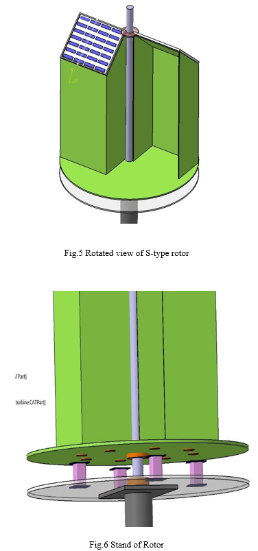
IV- Solar panels at the top of wind turbine to make the Right trapezoid shape.
IV. LITERATURE SURVEY
Mr. Sthita Prajna Mishra, Dr.S.M.Ali, Ms. Prajnasmita Mohapatra, Ms.Arjyadhara Pradhan, “A Hybrid System (Solar and Wind) Energy System for Remote Areas,” states that the collection of the solar panel was enhanced by 68.5% from that of the single panel with the help of reflectors and tracking. Further energy obtained using the windmill with addition of dedicated wind sensor and altered design together adds to an increase in the efficiency by an overall margin of above 50%. The paper explains the advantages and working hybridized wind and solar system. There are two types of solar systems; those that convert solar energy to D.C power, and those that convert solar energy to heat. Photovoltaic are solar cells that convert sunlight to D.C electricity. These solar cells in PV module are made from semiconductor materials. When light energy strikes the cell, electrons are emitted. The electrical conductor attached to the positive and negative scales of the material allow the electrons to be captured in the form of a D.C current. The wide spread use of PV generation is however mainly hampered by economic factors. Today the theoretical efficiency of a solar PV cell can be 25% - 30 % and a practical efficiency around 17%.To maximize the falling of sun rays on solar panel the proposed solution in this paper is to use reflectors which reflect rays toward panel and placed at an angle of 60 degrees. A wind turbine is a machine for converting the kinetic energy in wind into mechanical energy. Wind turbines can be separated into two basic types based on the axis about which the turbine rotates. Turbines that rotate around a horizontal axis are more common. Vertical-axis turbines are less frequently used. Wind turbines can also be classified by the location in which they are used as Onshore, Offshore, and aerial wind turbines. J.Godson,M.Karthick, T.Muthukrishnan, M.S.Sivagamasundari, “SOLAR PV-WIND HYBRID POWER GENERATION SYSTEM,” International Journal of Advanced Research in Electrical, Electronics and Instrumentation Engineering states that A portion of the energy requirement for a private house, farm house, a small company where used has been supplied with the electricity generated from the wind and solar power. It reduces the dependence on one single source and has increased the reliability Renewable energy sources i.e. Energy generated from solar, wind, biomass, hydro power, geothermal and ocean resources are considered as a technological option for generating clean energy. But the energy generated from solar and wind is much less than the production by fossil fuels, however, electricity generation by utilizing PV cells and wind turbine increased rapidly in recent years. This paper presents the Solar-Wind hybrid Power system that harnesses the renewable energies in Sun and Wind to generate electricity. Solar-Wind hybrid Power system is the combined power generating system by wind mill and solar energy panel. It also includes a battery which is used to store the energy generated from both the sources. Using this system power generation by windmill when wind source is available and generation from PV module when light radiation is available can be achieved. Both units can be generated power when both sources are available. By providing the battery uninterrupted power supply is possible when both sources are idle. Energy stored in the battery is drawn by electrical loads through the inverter, which converts DC power into AC power. The inverter has in-built protection for Short-Circuit, Reverse Polarity, Low Battery Voltage and Over Load.
Ashish S. Ingole, Prof. Bhushan S. Rakhonde,’Hybrid Power Generation System Using Wind Energy and Solar Energy,"states that hybrid power generation system is good and effective solution for power generation than conventional energy resources. It has greater efficiency. It can provide to remote places where government is unable to reach. So that the power can be utilize where it generated so that it will reduce the transmission losses and cost. Cost reduction can be done by increasing the production of the equipment. People should motivate to use the non-conventional energy resources. It is highly safe for the environment as it doesn’t produce any emission and harmful waste product like conventional energy resources. It is cost effective solution for generation. Hybrid energy system is the combination of two energy sources for giving power to the load. . In other word it can defined as “Energy system which is fabricated or designed to Extract power by using two energy sources is called as the hybrid energy system.” Hybrid energy system has good reliability, efficiency, less emission, and lower cost. In this proposed system solar and wind power is used for generating power. Solar and wind has good advantages than other than any other non-conventional energy sources. Both the energy sources have greater availability in all areas. It needs lower cost. There is no need to find special location to install this system.
Solar-wind hybrid energy systems needs only initial investment. It will compete well in generation with the conventional energy sources. When accounted for a lifetime of reduced or avoided utility costs. The cost of the system depends on the system chosen, wind resource on the site, electric costs in the area, and the battery bank required. Cost of the Wind-Solar Hybrid system is to be minimized. For minimize the cost of the system we need to increase the use of non-conventional energy sources. So that production of solar and wind power generator will be increase. That will reduce cost of the whole system.
Deshmukh and S.S Deshmukh, discuss methods of modeling and designing hybrid renewable energy systems, and also issues involved in increasing the penetration of such systems.
The input energy to PV system is solar radiation and total solar radiation on an inclined surface is estimated as
IT= IbRb + IdRd + (Ib+Id) Rr
Where Ib and Id are direct normal and diffuse solar radiations, Rd and Rr are the tilt factors for the diffuse and reflected part of the solar radiations.
Ravindra Kashyap : US7045702B2 United States
Solar-paneled windmill .A solar-paneled windmill is provided having aerodynamic fan blades provided with solar panels. The windmill produces electricity using wind energy and solar energy. In another embodiment, magnets are provided to the solar-paneled windmill fan blades to generate magnetic fields to increase the amount of electrical energy produced.
G.Thilak, S.Prabakaran, G.Sathi “Design And Analysis of Savonius wind Turbine with magnetic Repulsion” gives us all information about vertical wind turbine and use of it to generate electricity with help of magnetic repulsion. Wind energy conversion systems are an old concept in harnessing energy. Wind power was earlier used in small applications such as moving boats where sailing was employed, cooling houses, running machines in large farms, and even in small production facilities. The importance was redefined when conversion of the wind energy to electrical power highlighted a turning point for the wind power industries. Due to the impact in energy crisis and changes in the climates, wind turbines started to spread rapidly across the globe in the past decades. However, wind power is far from its full outcomes. Manufacturers have incrementally improved conventional wind turbines in the last few decades –but the greatest energy output has less starting torque. To overcome this we have used magnets to gain initial starting torque.
As we studied the research papers there some gaps , also considered the missing piece or pieces , hybridization is studied by every researcher also energy combinations but the wind and solar working mechanism combination not explored by any researcher , our focus is combing the both power plus the working mechanism as we know the solar panel charging angle is 45 degree to the solar rays for the maximum efficiency of panel so we are placing the panel at this angle also we are using this panel itself as the wind turbine blades with the help of air trapping blades of wind turbine.
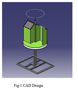
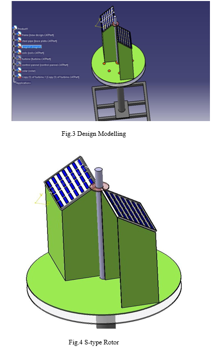
V. CAD MODELLING
VI. POWER CALCULATION
The wind turbine works on the principle of converting kinetic energy of the wind to mechanical energy.
The kinetic energy of any particle is equal to one half its mass times the square of its velocity,
K.E=1⁄2Mv² (1)
Where,
K.E=kinetic-energy
M=mass
v = velocity,
M = ρAV (2)
Subtituting eq. 2 in eq. 1
K E =1/2ρAV³ watts.
Where,
A= swept area of turbine.
ρ= density of air (1.225 kg/m³)
V=wind velocity.
Therefore power developed by wind turbine= 1⁄2ρAV³ watts.
Coefficient of power (CP)
Coefficient of power is the ratio of mechanical power developed by the turbine to power of wind.
CP=0.593
Power of Turbine (PT)
PT = 1⁄2ρAV³*CP watts
To find dimensions of turbine (H & D)
Assume: Power to be generated = 20 watt
Average wind speed = 6 m/s
PT = 1⁄2ρAV³*CP
20 = 1⁄2*1.225*A*(6)³*0.59
A= 0.2562 m²
Considering aspect ratio = 1.5
A=R*H
Therefore, A = R*(1.5R)
Where,
H= Height of turbine,
R= Radius of turbine
0.2562= R²*(1.5)
R=0.4132 m & H=0.6198 m
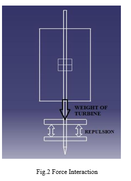
VII. MAGNETIC LEVITATION
Magnetic Levitation occurs when the two similar pole are repelled without each other. The ring shaped permanent magnets of grade N35 are used for the levitation.
Dimensions: Outer diameter = 40 mm
Inner diameter = 20 mm
Thickness =10mm
The force between this two like magnetic pole are to be calculated as,
F= Μqm1qm2/4πr²
Where,
qm1 & qm2= magnitudes of magnetic poles (Amp- mtr)
μ= permeability of intermediate medium as air, 4π*10-7 N/A-7
r= Distance between two magnetic pole.
qm1 & qm2=HC1, C2 *A= 900*103 A/m
F= μ0HC1HC2/4πr²
According to equilibrium forces;
∑F=0
Mg –F = 0
F = Mg
Where,
F is magnetic force, N
M is total mass of rotor to levitate, kg
g is gravitational acceleration m/s²
Therefore total weight of the turbine is around 4 kg.
F = 4*9.81= 39.24 N
Available Neodymium magnet with dimensions 40*20*10mm having capacity to repel 39.24 N force can be used for levitation between stator and rotor to maintain air gap.
Drag force is given by;
Fd =1/2 *ρ*A*V²*Cd
where;
Cd = coefficient of drag = 1.42
Fd = 1⁄2*1.225*.2562*6²*1.42
Fd = 8.02 N
Drag force is 8.02 N.
VIII. DESIGN OF MODEL
A digital mock up (DMU) designed as per standard part availability in market and there dimensions, A digital mock up (DMU) provides us with the basis for evaluating optimum package usage. As specialists in production-ready development, we make sure all components are ideally positioned – including the ability to accommodate components in terms of geometry and actually fixing them in position. To ensure production gets off to a smooth start. This is best industry method to design any machine using 3d software’s.
A. Catia v5 Software is used in this Model.
IX. MATERIAL SELECTION
Major Components of Maglev Vertical Axis Wind Turbine
- Blades
- Neodymium magnet
- Generator
A. Blades
A wide range of materials can be select as a turbine blade in wind turbines. Depending on a size of our project here we use aluminum for blade material. Aluminum is a metal like steel, brass, copper, zinc, lead or titanium. Aluminum is a very light metal with a specific weight of 2.7 g/cm2, about a third that of steel. Its strength can be adapted to the application required by modifying the composition of its alloys. Aluminum naturally generates a protective oxide coating and is highly corrosion resistant. Aluminum is a good reflector of visible light as well as heat, and that together with its low weight makes it an ideal material for reflectors in, for example, light fittings or rescue blankets. Aluminum is strong with a tensile strength of 70 to 700 MP depending on the alloy and manufacturing process. Extrusions of the right alloy and design are as strong as structural steel. This means that the moment of inertia has to be three times as great for an aluminum extrusion to achieve the same deflection as a steel profile.
|
Property |
Value |
|
Density |
2712 kg/m3 |
|
Thermal Conductivity |
0.180 Kw/m-C |
|
Specific Heat |
920 J/kg-C |
|
Modulus of Elasticity |
68947.570 MPa |
|
Poisson’s Ratio |
0.330 |
|
Yield Stress |
275.790 MPa |
|
Ultimate Stress |
310.264 MPa |
Table 1. Property Values of AL 6061-T6
B. Neodymium Magnets
Neodymium magnet is the composition of neodymium, iron, boron & few transition metals. Thus magnets are extremely strong for their small size, metallic in appearance and found in simple shape such as rings, blocks and disk. Neodymium magnets are develop rapidly and applied widely due to their perfect characteristics
|
Melting point |
1297 K |
|
Boiling point |
3347 K |
|
Density |
7.01 g/cm3 |
|
Heat of fusion |
7.14 kJ/mol |
|
Heat of vaporization |
289 kJ/mol |
|
Molar heat capacity |
27.45 J/mol. K |
|
Thermal expansion |
9.6 um/m.K |
|
Thermal conductivity |
16.5 W/m.K |
|
Young’s modulus |
41.4 GPa |
|
Shear modulus |
16.3 GPa |
|
Bulk modulus |
31.8 GPa |
|
Poisson ratio |
0.281 |
Table. 2 Properties of Neodymium Magnet
C. Selection of Neodymium Magnet
Some factors need to be assessed in choosing the permanent magnet selection that would be best to implement the maglev portion of the design. Understanding the characteristics of magnet materials and the different assortment of sizes, shapes and materials is critical. There are four classes of commercialized magnets used today which are based on their material composition each having their own magnetic properties. The four different classes are Alnico, Ceramic, Samarium Cobalt and Boron neodymium Iron also known Nd-Fe-B. Nd-Fe-B is the most recent addition to this commercial list of materials and at room temperature exhibits the highest properties of all of the magnetic materials the purpose of achieving vertical orientation with our rotors as well as the axial flux generator.
Table 3. Comparisons between Neodymium &Samarium Cobalt
|
Property |
Neodymium |
Samarium Cobalt |
|
Remanence (T) |
1-1.3 |
0.82-1.16 |
|
Coercivity (MA/m) |
0.875-1.99 |
0.49-1.59 |
|
Relative Permeability |
1.05 |
1.05 |
|
Density (g/cm3) |
7.3-7.5 |
8.2-8.4 |
|
Compressive Strength (N/mm2) |
1100 |
800 |
|
Tensile Strength (N/mm2) |
75 |
35 |
The magnetic repulsion will be strong enough to keep both magnets at a distance away from each other. The force created as a result of this repulsion can be used for suspension purposes and is strong enough to balance the weight of an object depending on the threshold of the magnets. In this project, we expect to implement this technology form.
D. Generator
The basic understanding of a generator is that it converts mechanical energy to electrical energy. Generators are utilized extensively in various applications and for the most part have similarities that exist between these applications. However the few differences present is what really distinguishes a system operating on a motors. With the axial flux generator design, its operability is based on permanent magnet alternators where the concept of magnets and magnetic fields are the dominant factors in this form of generator functioning. These generators have air gap surface perpendicular to the rotating axis and the air gap generates magnetic fluxes parallel to the axis. In further chapters we will take a detailed look into their basic operation and the configuration of our design.
E. Coil Design
The number of windings per coil produces a design challenge. The more windings will increase the voltage produced by each coil but in turn it will also increase the size of each coil. In order to reduce the size of each coil a wire with a greater sizes gage can be utilized. Again another challenge is presented, the smaller the wire becomes the less current will flow before the wire begins to heat up due to the increased resistance of a small wire. Each one of our coils has a measured resistance of 40 ?; a smaller gage wire would further reduce this resistance.
When designing a generator the application, which it will be used for, must be kept in mind. The question must be answered, which property, the current or the voltage, is of greater importance? The problem that is produced by a larger coil is the field density is decreased over the thickness of the coil.
The thickness of the coil is what reduces the flux magnitude. In our design we have chosen to sandwich the coils between two Attracting magnets this design will increase the field density greatly improving the voltage output. The increased thickness of a coil would therefore increase the distance between the two magnets reducing the flux. A balance must be found between the amount of voltage required and the amount of current required.
We have chosen to use a very high gage wire to increase the amount of voltage the generator can provide. If the generator is required to produce more current the coils can be replaced with those of a smaller gage wire. The permanent magnets we have chosen to use provide a very strong magnetic field.
F. Four Batteries in Series / Parallel connection
If the amount of current was more important in the output of the system, neglecting the voltage, the coils could have been replaced with lesser gauge and they could have been connected in parallel. You could also connect the batteries using a series-parallel connection. Then connect the two groups in parallel. Connect the – of the two coils (on the right in the picture) together and the + of the other two (on the left in the picture) together. The – of the coil on the top right in the picture connects to the – of the coil and the + of the coil on the top left in the picture connects to the + of the coil.
X. RESULTS AND DISCUSSIONS
|
Wind velocities at different location points on the turbine in m/s
|
Avg. Wind Speed in m/s
|
Speed Of Turbine in rpm
|
|||
|
V1 |
V2 |
V3 |
V4 |
||
|
0 |
0 |
0 |
0 |
0 |
0 |
|
0.2 |
0.5 |
0.3 |
0.5 |
0.325 |
17.12 |
|
0.5 |
0.7 |
0.9 |
0.8 |
0.725 |
18.3 |
|
0.8 |
1.1 |
1.3 |
1.1 |
1.075 |
20.2 |
|
1.3 |
1.6 |
2.2 |
1 |
1.525 |
23.1 |
|
1.6 |
1.8 |
1.6 |
0.8 |
1.45 |
27.4 |
|
1.1 |
2.9 |
1.7 |
2.5 |
2.05 |
38.7 |
|
3.3 |
3.5 |
3.2 |
2 |
3 |
46.3 |
Table 2. Testing and Result
XI. RESULTS AND DISCUSSIONS
- Clean And Efficient Source Of Power Generating Device Using Renewable source of Energy
- Design And Development of Power Generating Device with maximum possible efficiency.
References
[1] Mr.Sthita Prajna Mishra et.al,’A Hybrid System (Solar and Wind) Energy System for Remote Areas’, International Journal of Engineering Research And Development, 2012, pp.64-68. [2] J.Godson, M.Karthick et.al ‘Solar PV Wind Hybrid Power Generation System’, IJAREEIE, 2013, vol 2. [3] Ashish S. Ingole, Prof. Bhushan S. Rakhonde,’Hybrid Power Generation System Using Wind Energy and Solar Energy’, International Journal of Scientific And Research Publications, 2015. [4] M.k Deshmukh,S.S Deshmukh, Renewable and Sustainable Reviews,2006 [5] G.Thilak, S.Prabakaran, G.Sathi ,’Design And Analysis of Savonius wind Turbine with magnetic Repulsion’, IJARIIE. [6] Mayur Patel,Aditya Thakur et.al,’Design,Analysis & Fabrication of Maglev Vertical Axis Wind Turbine’, IJIRSET.
Copyright
Copyright © 2022 Saurabh J. Kamble, Prof. Dr. V. T. Tale. This is an open access article distributed under the Creative Commons Attribution License, which permits unrestricted use, distribution, and reproduction in any medium, provided the original work is properly cited.

Download Paper
Paper Id : IJRASET43840
Publish Date : 2022-06-05
ISSN : 2321-9653
Publisher Name : IJRASET
DOI Link : Click Here
 Submit Paper Online