

Ijraset Journal For Research in Applied Science and Engineering Technology
Design of Transmission Tower for a Sub Station of 132 KV
Authors: Pranjal Dupare, Amey Sarage, Atharva Nilawar, Nilakshi Somkunwar , Mangesh Bhorkar
DOI Link: https://doi.org/10.22214/ijraset.2023.52032
Certificate: View Certificate
Abstract
In order to properly plan and design a structure, it is necessary to have not only imagination and conceptual thinking, but also a solid understanding of the science of structural engineering, as well as practical knowledge of recent design codes and regulations, all supported by ample experience, intuition, and judgment, with the goal of ensuring safety while maintaining a careful balance between economy and safety. One type of steel structure that has seen significant progress in recent years is the transmission tower, which must be constructed with great care and maintenance in order to ensure the safety and comfort of surrounding beings. While traditional methods of designing and analyzing transmission towers can be time-consuming, software such as \"Spadaro V8i\" can be used to expedite the process. In this research manual calculation is done by traditional method and after that modelling is done with software.
Introduction
I. INTRODUCTION
Transmission Tower
Towers are tall structures with a height greater than their width, allowing for various functions to be achieved. They come in many types, including clock towers, castles, bridges, transmission towers, lighthouses, and signal towers. Transmission towers, specifically, are tall structures designed to support overhead power lines, transmitting electricity from generation stations to sub-stations in high voltage AC and DC systems. They come in a wide variety of shapes and sizes, with typical heights ranging from 15 to 55 meters (49 to 189ft), and are also known as power towers, cellular phone towers, or electric towers depending on their purpose. ISA sections, with dimensions according to steel tables, are commonly used to construct transmission towers, with K bracings, X bracings, and KX bracings used to reduce the total weight of the tower. When designing a transmission tower, several considerations must be taken into account, such as the minimum ground clearance of the lowest conductor point, the length of the insulator string, the minimum clearance to be maintained between conductors and the tower, and the location of the ground wire with respect to the outermost conductors. Additionally, transmission lines must be carefully designed to withstand natural disasters and meet requirements from both structural and electrical perspectives, with insulation and safe clearances of power carrying conductors from the ground being of utmost importance. The design of transmission towers is typically based on minimum weight, and they are often modeled as jointed space trusses using steel angle sections of different grade
II. LITERATURE REVIEW
Transmission line towers constitute about 28 to 42 percent of the cost of the transmission line. The transmission towers are constructed for transmitting the electricity from generation station to substations. The function of transmission tower is to support the conductor wires and ground wires at suitable distance and safe height from ground. Therefore, transmission line towers should be designed considering both structural and electrical requirements for a safe and economical design. In this study an attempt is made to model, analyze and design a 220kV double circuit transmission line towers. STAAD Pro program is going to be used for analysis and design of the members of 220kV double circuit tower. The transmission tower has a height of 32m and base width of 8m. [1,2] Transmission towers are essential for the purpose of supplying electricity to various regions of the nation. That’s why power stations are increased & provided at different corners where it’s needed. Interconnections between systems are also increasing to improve accuracy and economy. If Transmission line is not designed carefully, they can fail due to any natural disaster. That’s why it should be stable and carefully designed so that they do not fail during natural disaster. [3,4] The structural planning and design process includes not only creativity and logic, but also a solid understanding of structural engineering science, as well as practical knowledge of modern design codes and bye laws, as well as a wealth of experience, intuition, and judgement. [5,6] e categories: lattice, pole and guyed. The supports of EHV transmission lines are normally steel lattice towers.
The cost of towers constitutes about quarter to half of the cost of transmission line and hence optimum tower design will bring in substantial savings. The selection of an optimum outline together with right type of bracing system contributes to a large extent in developing an economical design of transmission line tower. The height of tower is fixed by the user and the structural designer has the task of designing the general configuration and member and joint details. [7,8]
III. METHODOLOGY
Methodology consists of collection of data, material used, study of research paper, calculation of various load acting on the tower and design of tower in software. Then analysis of tower in software, result and conclusion.
A. Transmission Tower Configuration
Below specified values are taken with reference to actual site condition and location as per IS 802:1995 (Part1/sec10), IS 875 part 3, IS 800:2007. In this study special importance is given to actual condition of concern area atmosphere, wind velocity, extreme climatic condition.
Table 1 Configuration of transmission tower
|
Parameters |
Values |
|
Reliability level |
2 |
|
Wind zone |
2 |
|
Terrain category |
2 |
|
Wind speed, Vb |
44m/s |
|
Design wind pressure, Pd |
1.5 KN/m2 |
|
Ground clearance, h1 |
7.00m |
|
Maximum sag of the lower most conductor wires, h2 |
6.7m |
|
Vertical distance between conductor wires, h3 |
4m |
|
Vertical distance between top conductor and ground wire, h4 |
3.125m |
|
Base width of the tower, b |
5.5m |
|
Length of each cross arms |
6 m |
|
Maximum sag of lower most conductor |
6.734m |
|
Temperature T1 |
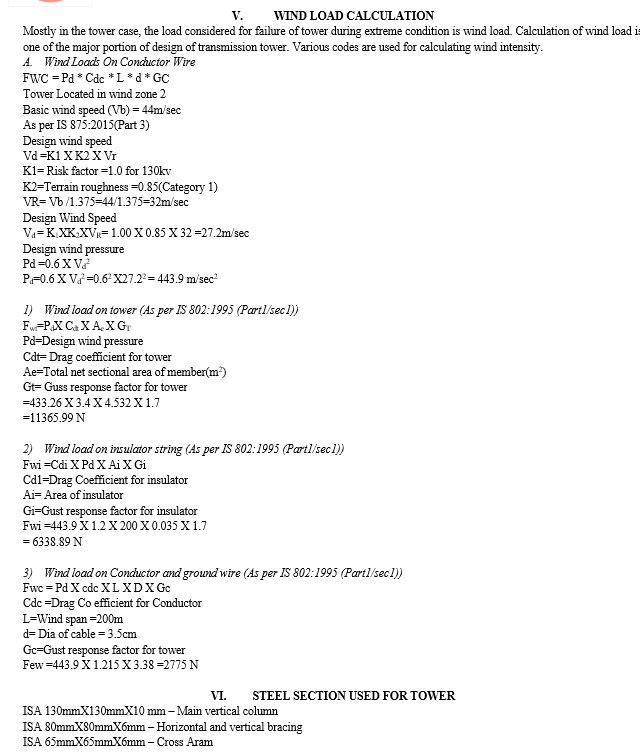
5 °C |
|
Temperature T2 |
60°C |
B. Properties of Conductor Wire
The capacity of conductor for transferring current over a large distant place is entirely depend upon the strands used in the conductor wire.so, the designer must ensure minimum specified limit as per concern Indian is code.
Table 2 Details of transmission tower conductor wire
|
Type of conductor |
ASCR conductors |
|
Voltage |
130 KV |
|
Conductor size |
6.54/30mm + 7/30mm |
|
Area of the conductor (for all strands) |
475.379mm2 or 4.7537cm2 |
|
Weight of the conductor(w) |
16.70 n/m |
|
Ultimate tensile strength |
13316kg or 130.30kN |
|
Coefficient of linear expansion(α) |
19.3X10⁻⁶ per oc |
|
Modulus of Elasticity (E) |
0842X105 N/M2 |
|
Diameter of the ASCR wire |
30MM |
C.. Properties of Earth Wire
Earth wire are the part of transmission tower which is place at the top of the tower, which acts as a insulator during the extreme rainfall. Probability of lighting fall on the tower is more, this wire act as earthing during storm.
3 Details of transmission tower earth wire
|
Type of earth wire |
Galvanized steel |
|
Size of the earth wire |
7/3.15mm |
|
Configuration |
One continuously to run horizontally on the top of the towers and conductors |
|
Overall diameter |
10MM |
|
Weight of conductor |
6N/M |
|
Ultimate tensile strength |
58.4kN or 5955.14 kg |
|
Area of cross- section |
545.5mm2 |
|
Coefficient of linear expansion |
11.5X10⁶/oc |
|
Modulus of elasticity |
1.933X10⁶kgf/cm2 |
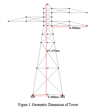
IV. TOWER GEOMETRY
Dimension of tower is determined as per Indian standard specification. Height of tower is fixed according to seismic zones, Climatic condition, Soil Bearing capacity. Selection of Indian standard angles are chosen from the previous research done. If this angles fails, selection of another greater dimension angle is to be considered. Calculation of maximum sag of conductor wire, Dimension of cross arm, Ground clearance is calculated.
Isolated footing for each four corners of transmission tower is constructed and analysis of such fixed condition is done in software. Soil present and their bearing capacity is tested by the plate bearing test before as per records of the previously constructed tower of double circuit.
VII. MODELING OF TOWER
STAADPRO V8i is a versatile software program that allows for modeling, static and dynamic analysis, non-linear dynamic analysis, and non-linear static pushover analysis. This program is user-friendly and offers a wide range of features. Specifically, STAAD.Pro V8i is an excellent choice for seismic analysis of multistory buildings with or without floating columns. It is an all-inclusive finite element analysis and design software, which includes a user-friendly interface, visualization tools, and design codes. STAAD.Pro V8i can analyze any structure exposed to static loading, dynamic response, wind, earthquake, and moving loads. It is capable of providing FEM analysis and design for various types of projects such as towers, culverts, plants, bridges, stadiums, and marine structures.
VIII. RESULTS AND DISCUSSIONS
As per the stud and modelling, analysis of tower in STAAD.PRO software, the angle section used in the tower for vertical, horizontal and in inclined member is passed against the load acting on the tower. According to result, used of such angle in actual tower is satisfactory or is the ideal design for specified location for which these research is carried out.
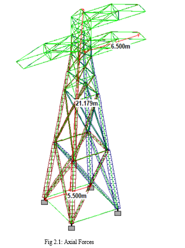
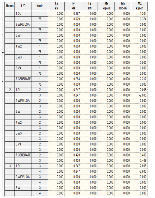
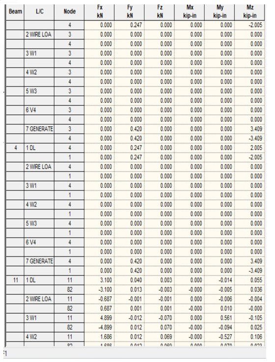
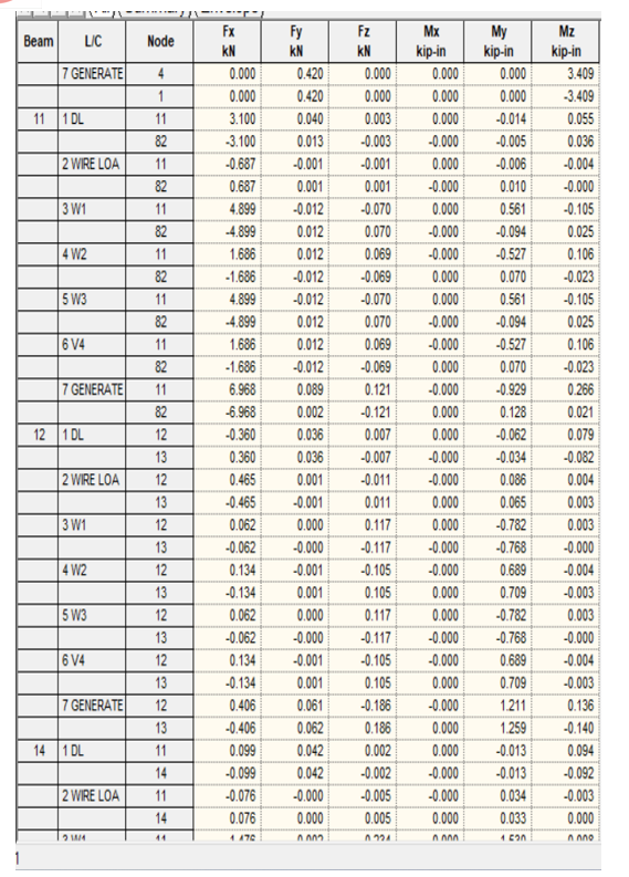
A. Axial Forces Acting In The Tower
Axial forces are the forces which is acting through the members longitudinal axis. For the determination of such forces various method is used. Below given are the axial forces acting in the various member of tower calculated in STAADPRO software
Conclusion
The growing demand for reliable and sufficient electricity supply in all sectors, driven by the increase in population, necessitates the use of transmission towers. These towers must be able to withstand dead load, live load, and wind load under normal operating conditions. The maximum nodal displacement occurs at the top node (13), with a displacement of 175.255 mm. All sections considered in the design have been found to be safe against critical load combinations. The estimated steel required for construction is 5.2 tones (51 KN). Further studies could focus on designing transmission towers with a more appealing aesthetic appearance. Dynamic loads should be applied during the tower\'s analysis. The quantity of steel required can be optimized by using different bracing systems. The cost of construction can be compared for different bracing systems.
References
[1] S B Chaudhari, J S Nikam, Dr. P D Jadhao. “ANALYSIS AND DESIGN OF TRANSMISSION TOWER WITH DIFFERENT CONFIGURATION AND BRACING SYSTEM”, IJSRD – International Journal of Science Research and Development, ISSN (Online):2321-0613 Volume 5, Issue 11, 2018. [2] Sai Avinash, Rajashekar P, Harinarayan R, Chamandeep and Yashdeep. “ANALYSIS AND DESIGN OF TRANSMISSION TOWER USING STAAD pro”, International Journal of Earth Science and Engineering ISSN: 0974- 5904, Volume 9 no.3. [3] Tanvi G Londhe, Prof. M S Kakamare. “REVIEW PAPER ON COMPARITIVE STUDY OF DYNAMIC ANALYSIS OF TRANSMISSION TOWER”, International Research Journal of Engineering and Technology (IRJET), ISSN (Online): 2395-0056, ISSN (print):2395-0072, August 2018. [4] Sayed Abdul Hussain, Bibek Samantha. “STRUCTURAL OPTIMIZATION AND DESIGN OF ELECTRIC TRANSMISSION TOWER”, International Journal of Innovative Research in Science, Engineering and Technology, ISSN (Online): 2319-8753 ISSN (print):2347-6710, Volume 7, Issue-6, June 2018. [5] Archana R, Aswathy S Kumar. “ANALYSIS AND DESIGN OF FOUR LEGGED TRANSMISSION TOWER”, International Journal of Science and Research (IJSR), ISSN (Online):2319-7064 Volume 5 Issue 7, July 2016. [6] Gopi Sundam Punse. “ANALYSIS AND DESIGN OF TRANSMISSION TOWER”. International Journal of Modern Engineering Research (IJMER), ISSN: 2249–6645, Volume 4, Issue 1, Jan. 2014. [7] D.B.Sonowal, J.D.Bharali, M.K.Agarwalla, N. Sarma, P. Hazarika. “Analysis and Design of 220 kV Transmission Line Tower (A conventional method of analysis and Indian Code based Design)”. IOSR Journal of Mechanical and Civil Engineering (IOSR-JMCE), e-ISSN: 2278-1684, p-ISSN: 2320–334X, PP 40 -49. [8] Arya, S., & Er. Sindhu, A. R. (2020). Analysis and Design of Transmission Tower with Isolated Footing. Journal of Science and Technology, 35-42. [9] B. Bharath Kumar Reddy, K. Rasagnya, & V. Sanjay Gokul. (2016). A Study on Analysis of Transmission Line Tower and Design of Foundation. International Journal of Engineering Development and Research , 2214-2224. [10] CH. Prasad Babu, & N. Vikram. (2020). DESIGN OF TRANSMISSION TOWER AND ITS FOUNDATION. IJARIIE, 364-375. [11] Heera Lal Bhardwaj, Ajit, & Yogesh Kaushik. (2015). Analysis and Design of Four Leg Steel Transmission Tower using Staad.Pro. International Journal of Advanced Engineering, Management and Science (IJAEMS) , 7-13.
Copyright
Copyright © 2023 Pranjal Dupare, Amey Sarage, Atharva Nilawar, Nilakshi Somkunwar , Mangesh Bhorkar. This is an open access article distributed under the Creative Commons Attribution License, which permits unrestricted use, distribution, and reproduction in any medium, provided the original work is properly cited.

Download Paper
Paper Id : IJRASET52032
Publish Date : 2023-05-11
ISSN : 2321-9653
Publisher Name : IJRASET
DOI Link : Click Here
 Submit Paper Online