

Ijraset Journal For Research in Applied Science and Engineering Technology
Designing of Water Distribution System using EPANET Software
Authors: Haritha K, Haripriya H N, Najmu Sahidha K A, Sridhar Hariharan A
DOI Link: https://doi.org/10.22214/ijraset.2023.52871
Certificate: View Certificate
Abstract
Introduction
I. INTRODUCTION
Next to air, the important requirement of human life to exist is water. It is available from various sources such as rivers, lakes, streams, etc. The importance of water in human life is so much that the development of many of the world’s ancient cities has taken place near water sources.
The reliance on the monsoon for the supply of water is also significant. Every living thing requires water for its survival, health, and sanitation. Moreover, it is the main raw material for production and many other users outside the home and farm.
In addition to the direct consumption of water at homes and farms, there are many indirect ways water affects our daily lives. For example, water plays a vital role in manufacturing essential commodities, electric power generation, transportation, and recreational and industrial activities. Thus water can be considered as the most important raw material of civilization. The water demand is increasing day by day, and hence every country has to take preventive measures to avoid pollution of the available water resources.
According to the Indian Constitution, legislating regarding matters related to the provision of drinking water supply and sanitation is the responsibility of the State governments as it falls in the state list included in its seventh schedule. The 73rd and the 74th Amendment to the constitution required the state governments to devolve drinking water and sanitation services to the Panchayati Raj Institutions (PRI) in rural areas or municipalities in urban areas, called Urban Local Bodies (ULB).
Various ministries share the responsibility for water supply and sanitation at the central and state level. At the central level, three ministries have responsibilities in this sector. The Ministry of Drinking Water and Sanitation (until 2011, the Department of Drinking Water Supply in the Ministry of Rural Development) is responsible for rural water supply and sanitation. The Ministry of Housing and Urban Poverty Alleviation and the Ministry of Urban Development share the responsibility for urban water supply and sanitation. There are about 100,000 rural water supply schemes in India. At least in some states, responsibility for service provision is in the process of being partially transferred from State 2 Water Boards and district governments to Panchayati Raj Institutions (PRI) at the block or village level. Blocks are an intermediate level between districts and villages.
Water plays a vital role in the life of all living organism. Water used for domestic purposes as well as irrigation and industrial purposes. A water distribution network should be designed such a way that it meets the demand of increased population. An adequate water supply can give better living standards. The water quality should not get deteriorated in the distribution pipes. The deficiencies of water supply in urban regions are becoming a major challenge for authorities. Because most of the water supply scheme are intermittent system. When using an intermittent system the water is distributed to residents for few hours in a day, hence most of the times the pipe lines are empty or partially full. A good water distribution network is the one which provide sufficient pressure at each point of distribution with less loss. A good water distribution network satisfies the consumer demand at required time. The design and analysis of water distribution network is a complex process in metropolitan areas where there is large number of pipes. In general, the layout of a water distribution network can be classified as dead end system, ring system, grid system or radial system. A dead end system has water mains along the roads without a particular pattern for towns that do not have road network patterns. A radial system delivers water into multiple zones. At the center of each zone, the water is delivered radially toward the customers. A grid system follows the general layout of the grid road infrastructure with water mains and branches connected in rectangles. Drawbacks of this topology include difficulties of sizing the system. A ring system is a topology with each water main that go to each road, and there is a sub-main that is branched off the water main to provide a circulation of two directions. This system has many advantages over the grid system. The three methods of water distribution are gravitational system, pumping system and combined gravity and pumping system. In gravity system, the water from a high leveled source is distributed to the consumers at low levels by the mere action of gravity without pumping. This method is the most economical and reliable since no pumping involved. However this method needs lakes or reservoir as a source of supply. In the pumping system the treated water is directly pumped into the distribution mains without storing anywhere.
It is also known as pumping without storage system. In a combined gravity and pumping system, the treated water is pumped at a constant rate and stored into an elevated distribution reservoir. This system helps in operating the pumps at constant speed at their rated capacities, thus increasing their efficiency and reducing their wear and tear. This type of system is invariably and almost universally adopted.
A. EPANET
EPANET was developed by the water supply and water resources division (formally the drinking water research division) of the Environmental Protection Agency’s National risk Management Research Laboratory.
EPANET is a computer program that performs extended period simulation of hydraulic and water quality behavior within pressurized pipe networks. A network consists of pipes, nodes, pumps, valves and storage tanks or reservoirs. EPANET tracks the flow of water in each pipe, the pressure at each node, the height of water in each tank, and the concentration of a chemical species throughout the network during a simulation period comprised of multiple time steps. In addition to chemical species, water age and source tracing can also be simulated. Typical uses for the EPANET model would include hydraulic calibration using chemical tracers (e.g., fluoride), design of sampling programs, evaluation of modified system operation (e.g., altered source utilization or tank operation), selection of satellite treatment locations, and use of targeted pipe clean- ing and replacement to enhance water quality.
EPANET is designed to be a research tool for improving our understanding of the movement and fate of drinking water constituents within distribution systems. It contains a state of-the-art hydraulic analysis engine that includes the following capabilities:
- Places no limit on the size of the network that can be analysed.
- Computes friction head loss using the Hazen-William, Darcy-Weisbach or ChezyManning formula.
- Includes minor head losses for bends, fittings, etc.
- Models constant or variable speed pumps.
- Computes pumping energy and cost.
- Models various types of valves including shutoff, check, pressure regulating, and flow control valves.
- Allows storage tanks to have any shape (i.e., diameter can vary with height).
- Considers multiple demand categories at nodes, each with its own pattern of time variation.
- Models pressure-dependent flow issuing from emitters (sprinkler heads).
- Can perform system operation on both simple tank level and timer controls and on complex rule-based controls.
It can be used for many different kinds of applications in distribution systems analysis. Sampling program design, hydraulic model calibration, chlorine residual analysis, and consumer exposure assessment are some examples. Running under Windows, EPANET provides an integrated environment for editing network input data, running hydraulic and water quality simulations, and viewing the results in a variety of formats. These include color-coded network maps, data tables, time series graphs, and contour plots.
B. Aim
To design a water distribution system and analyse it using water simulating software EPANET at Anakkara Grama panchayath.
C. Objectives
The main objective of this project is to plan and design a suitable water supply system for Anakkara panchayath. This includes,
- Forecasting the population for the design period
- Estimating the water demand
- Designing the layout of distribution system
- Analysis of distribution system using EPANET software.
D. Scope
The other manual methods used for the design of water distribution system consumes more time whereas the EPANET helps to save the time. This is freely downloadable and it does not have any charges. In future this software can make lot of innovations and can make the water distribution system more simplest and easier by installing EPANET in all water distribution network increases the accuracy. This software performs hydraulic and water quality analysis of water distribution network. Also determine the required amount of disinfectant to be used for disinfection of water. In this project, the amount of chlorine required for each node is calculated by using trial and error method.
II. LITERATURE REVIEW
Athulya.T, Anjali.K.Ullas (2020) studied that a water distribution network should be designed such a way that it meets the demand of increased population. An adequate water supply can give better living standard. The deficiencies of water supply in urban regions are becoming a major challenge for authorities. Because most of the water supply scheme are intermittent system. When using an intermittent system the water is distributed to residents for few hours in a day, hence most of the times the pipe lines are empty or partially full.
A good water distribution network is the one which provide sufficient pressure at each point of distribution with less loss. A good water distribution network satisfies the consumer demand at required time. The design and analysis of water distribution network is a complex process in metropolitan areas where there is large number of pipes. The major purpose of providing a good distribution network is to provide sufficient pressure at each point with less loss. A water distribution network consists of pipes, valves, tanks etc. EPANET is a computer programme that tracks the flow of water in each pipe, the pressure at each node and height of water in each tank. Hardy-Cross method is a manual method that makes corrections to initial assumed value by using equations. In this paper it was used to carry out the design and hydraulic analysis of water distribution network using EPANET software and Hardy-Cross method. The method of distribution used here is combined gravity and pumping system. The performance of system designed using EPANET was later compared with manual method. It was obtained that the pressure at all junctions and flow with their velocities at all pipes are feasible.
Harshan K G, Keerthana L Madhu & Anjali A (2018) compared Hardy Cross method with results from EPANET software. The distribution layout used here is loop system which is according to the layout of the area. The results were checked for accuracy using Hardy-Cross method for one loop. In manual calculation using Hardy-Cross method, for a single loop it took about forty iterations. It is time consuming and the chance of causing error is high. For a large area, it includes larger number of loops and hence the calculation and design part itself may take many years. The number of professionals needed for the completion of work will also be high.
Future studies are also recommended for more areas for validation of results. The EPANET software is a simple tool for the design of water distribution network. If proper water distribution networks are not laid, it will affect the water supply of the whole areas served by the system. To design a water distribution system a thorough study of the nearby available water resources, existing distribution network, water demand and required discharge etc are necessary. Since manual design becomes difficult, software assisted analysis are nowadays used.
Manoj Nallanathel , B. Ramesh , A P Santhosh(2018) analyzed the flow of water in water distribution network throughout the campus and checked whether there is any shortage of water at particular node. And also explains about the daily usage of water in the campus. From the obtained results, the pressure is quite enough to serve all buildings in campus i.e. the maximum pressure is 33.32 m and the flow is also quite reasonable for transporting the water to the consumers. The velocity will be always low, because of the gravity flow network.
At peak hours also the pressure at the junctions is quite enough to supply the water to the customers. Peak hour 4 am – 5 am, where the water is distributed from main tank to other individual tanks over the building. The water demand in the peak hour is 162.6 m3/h and during non peak hour is 33.6 m3/h. Excess water can be stored in sumps or underground tanks and later it can be used in peak hours. The overall supply of water is 1600 m3in one day but the required demand is around 1200 m3. By considering all the conditions and results obtained from the analysis concluded that there is no shortage of water while distributing the water.
R. K. Rai, and P. S. Lingayat ,(2019)studied that EPANET software is time saving and has no limitation for number of nodes, number of pipes or pumps to be modelled and analysed in it so complex networks can be easily solved. As the number of iterations increase, the value of head loss becomes closer to zero and to verify the obtained answers, balancing of flows at each point is done. The results obtained using Hardy Cross method and EPANET software are nearly equal. Newton-Raphson method is quite difficult to for the analysis of large network, but it gives acceptable result in less number of iteration. This paper aims to develop a simple procedure for analysis of water distribution network using hardy cross method with the help of electronic spreadsheets and EPANET. Engineers may not have enough time to monitor all the hydraulic parameters under different operating conditions. Hence a number of modification attempts to the standard solution methods for the development of a powerful algorithm may help to assess both steady- state solution and particularly time dependent simulations of water distribution systems when the nodal demands change on a daily basis. This paper highlights the effective analysis and distribution of network of pipes using EPANET tool as well as Hardy Cross method and Newton-Raphson method. The findings may help to understand the pipelines system of the study area in a better way. This work deals with the analysis of urban water distribution network in developing countries.
Venkata Ramanaa, Ch. V. S. S. Sudheerb B.Rajasekharc (2017) studied that a numerical model of a water distribution network designed for a town with 50,000 inhabitants was implemented in EPANET. Demonstrated that an efficient method for analysing pipe networks consists in solving the generalized loop equations by means of the Newton-Raphson method combined with the linear theory method as a simple and robust starting procedure. The paper also presents a methodology for computing the chlorine residual concentration in the urban area for 3 days of simulation period. Chlorine concentration of 0.45 mg/l was injected at the source tank. Final data are reported for the third day of the simulation, at three representative time moments, namely: the average daily consumption moment, an off-peak hour and a peak consumption hour.
III. METHODOLOGY
Initially the map of study area was extracted by using Google Earth software. The obtained map was then converted into EPANET file. Elevation, pipe diameter and length had given to each node and pipe for hydraulic analysis by using scale tool from Google earth software. Total area was divided into two grids and demand path is estimated by depending on the number of houses living in the area taken in grid.
A. Design Considerations
The layout of the distribution network is drawn based on the existing road pattern. Length of the pipe is taken as the road length. The diameter of the pipe is considered based on the purpose served by the pipe, such as main, sub main, branch pipes. Pipe roughness coefficient is taken 120, since Galvanized Iron pipes are used. The simulation period was set for 24 hours.
B. Estimating population
The knowledge of population is essential for designing any water supply scheme, as the supply should be sufficient to satisfy the people’s demand during the entire design period. The populations are increased by births, decreased by deaths, increased/decreased by migration, and increased by annexation. These all four factors affect the change in population. The present population may be obtained from the census record. The forecast is done by an appropriate method depending on the nature of the city, its environment, possible development of trade and industries, etc.
C. Demand Calculation
Geometrical Increase Method is used for population forecasting. In this method the percentage increase in population from decade to decade is assumed to remain constant. Geometric mean increase is used to find out the future increment in population. Since this method gives higher values and hence should be applied for a new industrial town at the beginning of development for only few decades.
The population at the end of nth decade ‘Pn’ can be estimated as:
Pn = P (1+ IG/100)n
Where, IG = geometric mean (%)
P = Present population
N = no. of decades
The design period for the system is taken as thirty years. After the population forecast the maximum daily demand was calculated using the general equations. Also the minimum required diameter is calculated.
D. Steps in Using EPANET
The layout of the distribution network is drawn based on the existing road pattern in an AUTOCAD file. This network is now converted into an EPANET file by using various software such as “EPACAD”. EPACAD converts the AUTOCAD file to EPANET file by considering intersections of the lines as nodes and lines as links. Then edit the properties of the objects that make up the system. The input parameters for each nodes and pipes are to be properly assigned. Describe how the system is operated. Then select a set of analysis options. Finally run a hydraulic/water quality analysis. The last step is to view the results of the analysis.
E. Model Input Parameters
In order to analyze the water distribution network using EPANET following input data files are needed:
- Junction Report: Junctions are points in the network where links join together and where water enters or leaves the network. The basic input data required for junctions are:
- Elevation above some reference (usually mean sea level)
- Water demand (rate of withdrawal from the network)
- Initial water quality
The output results computed for junctions at all time periods of a simulation are:
- Hydraulic head (internal energy per unit weight of fluid)
- Pressure
- Water quality
2. Pipe Report: Pipes are links that convey water from one point in the network to another. EPANET assumes that all pipes are full at all times. Flow direction is from the end at higher hydraulic head (internal energy per weight of water) to that at lower head.
The principal hydraulic input parameters for pipes are:
- Start and end nodes
- Diameter
- Length
- Roughness coefficient (for determining Head-loss)
- Status (open, closed, or contains a check valve)
The output results for pipes include:
- Flow rate
- Velocity
- Head-loss
- Darcy-Weisbach friction factor
- Average reaction rate (over the pipe length)
- Average water quality
The hydraulic head lost by water flowing in a pipe due to friction with the pipe walls can be computed using one of three different formulas:
- Hazen-Williams formula
- Darcy-Weisbach formula
- Chezy-Manning formula
The Hazen-Williams formula is the most commonly used head loss formula in Kerala by Kerala Water Authority.
IV. PRELIMINARY DATA COLLECTION
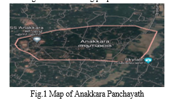
A. Study Area
Anakkara Grama panchayath is the oldest habitations in Palakkad district. Bhararthapuzha is skirting along the boundary of this project. The other local water sources are ponds, open wells and bore wells. Majority of the open wells and ponds go dry during summer season. These are extensively used for irrigation and drinking purposes.
Majority of the families are depending on the open wells and bore wells for their drinking water needs. Majority of the open wells dry up during summer. Due to the high density of bore wells and excessive pumping for irrigation/ drinking purpose have resulted in sharp decline of the ground water table, which in turn affected the open wells as well as bore well in the vicinity. At present, no water supply scheme is in use in the selected area. Hence a comprehensive scheme is to be designed. Efficient scheme components and lines are an absolute necessity to satisfy the drinking water needs of these portions .The terrain of the project area is more or less undulating with hard soil.
- Open Wells
The Grama panchayath have a large number of open wells, most of them with the private owners. Majority of population depend on these open wells for their drinking and other domestic needs. Majority of these wells are non- perennial and dry up during summer months of March to May.
2. Bore Wells
There are few bore wells in the Anakkara Grama panchayath cater a substantial number of households for their domestic and agricultural needs. Indiscriminate and uncontrolled drilling of bore wells and excessive pumping from these wells have resulted in fast depletion of ground water resources and lowering of ground water table.
3. Socio Economic Status
The main occupation of the people in the Scheme area is Agriculture. The main agriculture products are paddy, coconut, Areca nut, rubber, pepper plantation etc. Manufacturing of umbrellas, ceramic wares, garments, surgical materials, bricks, food products such as pappad, tailoring, wood industries etc are the major small scale industries in these panchayath. According to the details collected from the concerned offices, 90 % (average figure) of the total number of houses have sanitary latrines. Hence the sanitary status is satisfactory. The average literacy percentage is about 90 %. There are many LP schools, UP schools and higher secondary schools catering to the basic education needs of the people in the project area and nearby areas. There are many clinics and health centers in this area.
4. Source
To make the scheme successful, it is also necessary to have an adequate source of water supply the aspects of the scheme, namely demand of water, and available quantity of water, should balance each other. The source of the scheme is River Bhrathappuzha ( Intake Well cum pump house on the bank of Bhrathappuzha). As per the details received from Water Resource Department (WRD), the source is capable of meeting water requirement of the system for the design period.
B. Forecasting Population
Design of water supply and sanitation scheme is based on the projected population of a particular city or town, estimated for the design period. Any underestimated value will make system inadequate for the purpose intended; similarly overestimated value will make it costly. Change in the population of the city over the years occurs, and the system should be designed taking into account of the population at the end of the design period.
Factors affecting changes in population are:
- Increase due to births
- Decrease due to deaths
- Increase/ decrease due to migration
- Increase due to annexation.
The present and past population record for the city can be obtained from the census population records. After collecting these population figures, the population at the end of design period is predicted using various methods as suitable for that city considering the growth pattern followed by the city.
Geometric increase method is used for population forecasting. In this method, percentage increase is assumed to be the rate of growth and the average of the percentage increases is used to find out future increments in population. This method gives higher value and mostly applicable for growing towns and cities having vast scope for expansion.
Water Supply projects are usually designed to meet the requirements over thirty years after their completion.
The time lag between design and completion of the project should also be taken into account, which should not exceed two years to five years, depending on the size of the project. The thirty-year period may, however, be modified regarding certain components of the project depending on their useful life or the facility for earning out extensions when required and the rate of interest so that expenditure far ahead of utility is avoided.
Table shows the ward wise population in 2011 as per census records and expected population of the area at in 2051 and no. of households.
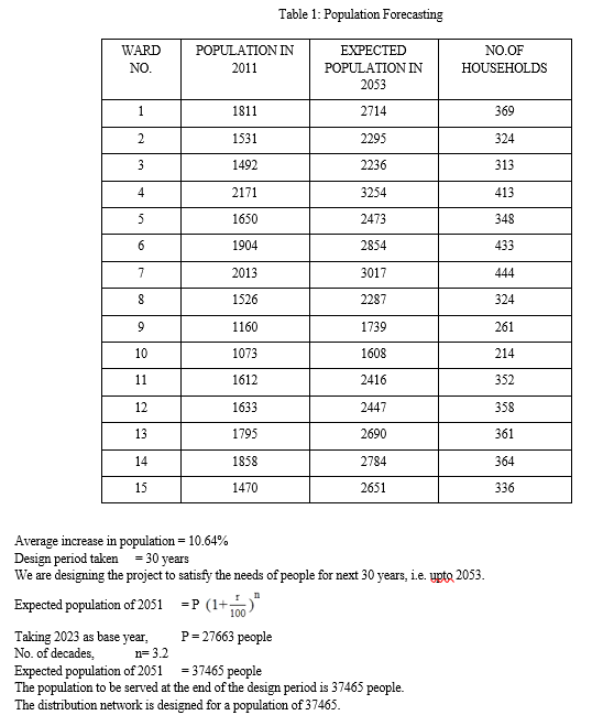
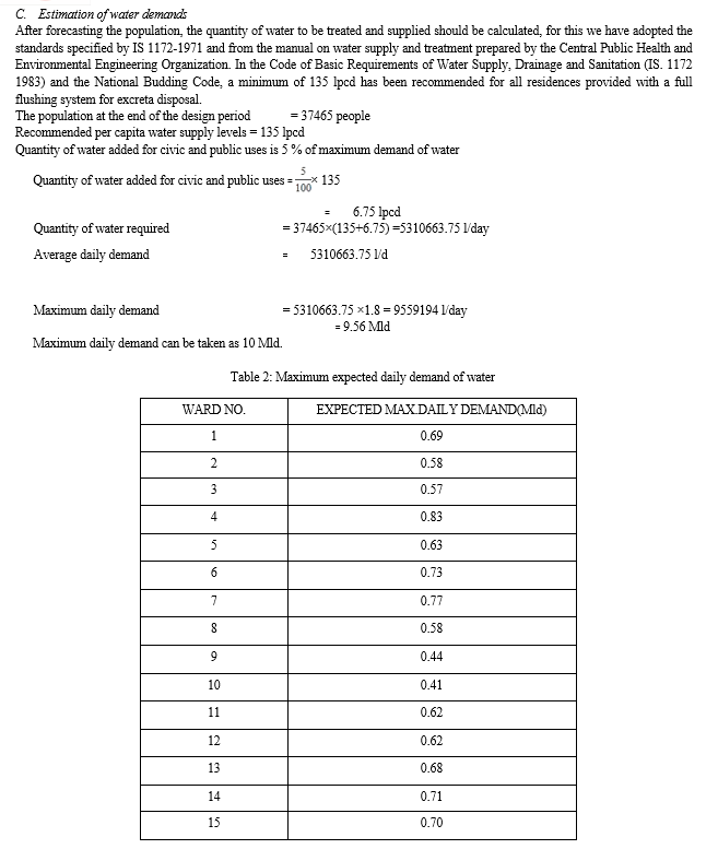
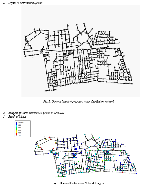
Table 3: Result of nodes
|
|
Elevation |
Head |
Pressure |
|
Node ID |
m |
m |
m |
|
n1 |
20.33 |
29.46 |
9.13 |
|
n2 |
16.26 |
29.46 |
13.2 |
|
n4 |
15.78 |
29.46 |
13.68 |
|
n5 |
19.46 |
29.46 |
10 |
|
n6 |
21.34 |
29.49 |
8.15 |
|
n7 |
19.13 |
29.44 |
10.31 |
|
n8 |
15.78 |
29.46 |
13.68 |
|
n9 |
20.99 |
29.66 |
8.67 |
|
n10 |
22.5 |
29.69 |
7.19 |
|
n11 |
23.48 |
29.7 |
6.22 |
|
n12 |
22.29 |
30.1 |
7.81 |
|
n13 |
21.93 |
29.71 |
7.78 |
|
n15 |
21.34 |
29.77 |
8.43 |
|
n16 |
26.84 |
29.65 |
2.81 |
|
n17 |
17.28 |
29.2 |
11.92 |
|
n18 |
16.88 |
29.19 |
12.31 |
|
n20 |
5.81 |
29.2 |
23.39 |
|
n21 |
15.1 |
29.19 |
14.09 |
|
n22 |
15.07 |
29.19 |
14.12 |
|
n23 |
16.26 |
29.18 |
12.92 |
|
n24 |
16.05 |
29.18 |
13.13 |
|
n26 |
16.29 |
29.18 |
12.89 |
|
n27 |
15.33 |
29.17 |
13.84 |
|
n29 |
15.93 |
29.19 |
13.26 |
|
n30 |
20.28 |
29.43 |
9.15 |
|
n31 |
16.62 |
29.43 |
12.81 |
|
n32 |
22.89 |
29.55 |
6.66 |
|
n33 |
20.52 |
29.78 |
9.26 |
|
n35 |
20.93 |
29.55 |
8.62 |
|
n36 |
20.8 |
29.82 |
9.02 |
|
n37 |
17.69 |
29.8 |
12.11 |
|
n38 |
17.66 |
29.79 |
12.13 |
|
n39 |
18.55 |
29.79 |
11.24 |
|
n40 |
12.14 |
29.8 |
17.66 |
|
n41 |
11.68 |
30.21 |
18.53 |
|
n42 |
17.23 |
30.4 |
13.17 |
|
n43 |
16.98 |
30.63 |
13.65 |
|
n44 |
15.04 |
30.62 |
15.58 |
|
n45 |
17.94 |
29.44 |
11.5 |
|
n46 |
16.75 |
29.4 |
12.65 |
|
n48 |
14.74 |
29.43 |
14.69 |
|
n49 |
13.31 |
29.26 |
15.95 |
|
n50 |
12.05 |
29.19 |
17.14 |
|
n51 |
15.41 |
29.32 |
13.91 |
|
n52 |
11.27 |
29.21 |
17.94 |
|
n53 |
13.29 |
29.15 |
15.86 |
|
n54 |
15.12 |
29.15 |
14.03 |
|
n55 |
16.97 |
29.04 |
12.07 |
|
n56 |
13.25 |
29.04 |
15.79 |
|
n57 |
16.94 |
29.1 |
12.16 |
|
n58 |
16.96 |
29.15 |
12.19 |
|
n59 |
16.03 |
29.15 |
13.12 |
|
n60 |
16.5 |
29.2 |
12.7 |
|
n62 |
14.34 |
29.2 |
14.86 |
|
n63 |
15.95 |
29.3 |
13.35 |
|
n64 |
15 |
29.5 |
14.5 |
|
n66 |
16.77 |
29.17 |
12.4 |
|
n67 |
18.22 |
29.17 |
10.95 |
|
n68 |
17.04 |
29.07 |
12.03 |
|
n69 |
21.75 |
29.04 |
7.29 |
|
n70 |
12.68 |
29.04 |
16.36 |
|
n71 |
17.39 |
29.01 |
11.62 |
|
n72 |
15.56 |
29.43 |
13.87 |
|
n73 |
17.68 |
29.32 |
11.64 |
|
n74 |
15.53 |
29.01 |
13.48 |
|
n75 |
13.96 |
29.03 |
15.07 |
|
n76 |
15.32 |
29.05 |
13.73 |
|
n77 |
20.67 |
28.99 |
8.32 |
|
n79 |
22.46 |
28.99 |
6.53 |
|
n80 |
21.71 |
28.99 |
7.28 |
|
n81 |
21.71 |
29 |
7.29 |
|
n82 |
22.4 |
29 |
6.6 |
|
n84 |
23.08 |
28.99 |
5.91 |
|
n85 |
22.39 |
29 |
6.61 |
|
n86 |
21.81 |
29 |
7.19 |
|
n87 |
20.57 |
29.01 |
8.44 |
|
n89 |
13.51 |
29.17 |
15.66 |
|
n90 |
22.31 |
29.02 |
6.71 |
|
n91 |
21.85 |
29 |
7.15 |
|
n92 |
14.08 |
28.98 |
14.9 |
|
n94 |
12.46 |
28.98 |
16.52 |
|
n95 |
18.43 |
28.99 |
10.56 |
|
n96 |
12.29 |
28.98 |
16.69 |
|
n97 |
18.74 |
28.99 |
10.25 |
|
n98 |
19.82 |
28.99 |
9.17 |
|
n99 |
19.5 |
28.99 |
9.49 |
|
n101 |
20.4 |
29.07 |
8.67 |
|
n102 |
17.04 |
29.06 |
12.02 |
|
n103 |
17.78 |
28.99 |
11.21 |
|
n104 |
18.51 |
28.99 |
10.48 |
|
n105 |
20.32 |
28.99 |
8.67 |
|
n106 |
22.79 |
28.99 |
6.2 |
|
n107 |
18.51 |
28.98 |
10.47 |
|
n108 |
17.03 |
30.91 |
13.88 |
|
n110 |
16.7 |
32.85 |
16.15 |
|
n111 |
19.24 |
33.16 |
13.92 |
|
n114 |
18.01 |
33.41 |
15.4 |
|
n115 |
17.28 |
32.88 |
15.6 |
|
n116 |
16.93 |
30.69 |
13.76 |
|
n118 |
21.11 |
29.73 |
8.62 |
|
n119 |
20.03 |
29.74 |
9.71 |
|
n120 |
21.27 |
29.76 |
8.49 |
|
n122 |
15.73 |
30 |
14.27 |
|
n123 |
17.69 |
30.03 |
12.34 |
|
n124 |
16.98 |
30.07 |
13.09 |
|
n125 |
18.2 |
29.99 |
11.79 |
|
n127 |
15.44 |
30.01 |
14.57 |
|
n128 |
16.05 |
30.01 |
13.96 |
|
n129 |
14.31 |
30.01 |
15.7 |
|
n130 |
16.01 |
30.02 |
14.01 |
|
n131 |
15.55 |
30.45 |
14.9 |
|
n133 |
16.93 |
30.55 |
13.62 |
|
n134 |
16.91 |
30.51 |
13.6 |
|
n135 |
16.19 |
30.49 |
14.3 |
|
n136 |
15.9 |
30.45 |
14.55 |
|
n137 |
17.81 |
30.47 |
12.66 |
|
n138 |
25 |
30.44 |
5.44 |
|
n139 |
17.7 |
32.4 |
14.7 |
|
n140 |
17.96 |
32.83 |
14.87 |
|
n141 |
19.72 |
33.55 |
13.83 |
|
n142 |
17.29 |
33.42 |
16.13 |
|
n143 |
20.32 |
34.36 |
14.04 |
|
n144 |
28 |
36.45 |
8.45 |
|
n145 |
18.21 |
33.56 |
15.35 |
|
n150 |
15.94 |
30.61 |
14.67 |
|
n152 |
12.79 |
29.92 |
17.13 |
|
n153 |
17.96 |
32.48 |
14.52 |
|
n154 |
18.1 |
32.76 |
14.66 |
|
n156 |
21.18 |
33.6 |
12.42 |
|
n157 |
21.11 |
33.6 |
12.49 |
|
n161 |
22.76 |
29 |
6.24 |
|
n162 |
14.76 |
28.99 |
14.23 |
|
n163 |
19.32 |
30.43 |
11.11 |
|
n164 |
30 |
30.42 |
0.42 |
|
n165 |
17.72 |
30.42 |
12.7 |
|
n167 |
17.38 |
30.43 |
13.05 |
|
n168 |
14.84 |
30.44 |
15.6 |
|
n169 |
30 |
30.44 |
0.44 |
|
n171 |
33.78 |
41.54 |
7.76 |
|
n173 |
40 |
45.03 |
5.03 |
|
n176 |
14.48 |
30.03 |
15.55 |
|
n177 |
13.75 |
30.03 |
16.28 |
|
n178 |
10.53 |
30.03 |
19.5 |
|
n179 |
12.7 |
30.01 |
17.31 |
|
n180 |
14.06 |
30.02 |
15.96 |
|
n181 |
30 |
41.65 |
11.65 |
|
n183 |
30.34 |
41.83 |
11.49 |
|
n184 |
32.69 |
41.37 |
8.68 |
|
n185 |
26.6 |
35.52 |
8.92 |
|
n188 |
23.35 |
34.57 |
11.22 |
|
n189 |
26.75 |
35.11 |
8.36 |
|
n190 |
26.73 |
34.98 |
8.25 |
|
n191 |
17.82 |
34.94 |
17.12 |
|
n192 |
22.69 |
34.95 |
12.26 |
|
n193 |
15.45 |
34.95 |
19.5 |
|
n194 |
33 |
44.09 |
11.09 |
|
n196 |
16.34 |
30.06 |
13.72 |
|
n199 |
16 |
30.06 |
14.06 |
|
n201 |
16.34 |
30.11 |
13.77 |
|
n202 |
50 |
65.4 |
15.4 |
|
n204 |
17.93 |
34.91 |
16.98 |
|
n205 |
15.71 |
34.88 |
19.17 |
|
n206 |
17.18 |
34.86 |
17.68 |
|
n207 |
17.9 |
34.86 |
16.96 |
|
n208 |
17.85 |
34.86 |
17.01 |
|
n209 |
16.52 |
34.86 |
18.34 |
|
n210 |
18.82 |
34.87 |
16.05 |
|
n211 |
19.29 |
34.87 |
15.58 |
|
n214 |
21.59 |
34.87 |
13.28 |
|
n215 |
22.28 |
34.9 |
12.62 |
|
n216 |
19.97 |
34.89 |
14.92 |
|
n219 |
22.12 |
34.89 |
12.77 |
|
n220 |
15.94 |
34.89 |
18.95 |
|
n221 |
16.72 |
34.89 |
18.17 |
|
n222 |
21.6 |
34.89 |
13.29 |
|
n223 |
16.07 |
34.89 |
18.82 |
|
n224 |
30.42 |
43.11 |
12.69 |
|
n225 |
36 |
44.37 |
8.37 |
|
n226 |
16.66 |
29.46 |
12.8 |
|
n227 |
15.4 |
30.45 |
15.05 |
|
n229 |
21.87 |
30.23 |
8.36 |
|
n230 |
31.56 |
42.88 |
11.32 |
|
n231 |
28.27 |
36.51 |
8.24 |
|
n232 |
19.56 |
29.79 |
10.23 |
|
n233 |
22.76 |
29.79 |
7.03 |
|
n234 |
21.73 |
29.76 |
8.03 |
|
n235 |
16.8 |
29.11 |
12.31 |
|
n236 |
21.28 |
28.99 |
7.71 |
|
n237 |
17.62 |
28.99 |
11.37 |
|
n238 |
16.84 |
28.99 |
12.15 |
|
n239 |
17.39 |
29.24 |
11.85 |
|
n241 |
23 |
30.1 |
7.1 |
|
n242 |
24.55 |
34.46 |
9.91 |
|
n244 |
15.22 |
34.89 |
19.67 |
|
n246 |
15.73 |
29.19 |
13.46 |
|
n247 |
16.81 |
29.2 |
12.39 |
|
n249 |
10.32 |
29.17 |
18.85 |
|
n250 |
10 |
29.16 |
19.16 |
|
n252 |
15.5 |
29.18 |
13.68 |
|
n253 |
16.91 |
29.22 |
12.31 |
|
n255 |
14.93 |
30.01 |
15.08 |
|
n256 |
19.32 |
29.94 |
10.62 |
|
n257 |
16.2 |
29.97 |
13.77 |
|
n260 |
19.08 |
29.79 |
10.71 |
|
n261 |
15 |
29.46 |
14.46 |
|
n263 |
11.64 |
29.19 |
17.55 |
|
n264 |
9.66 |
29.2 |
19.54 |
|
n265 |
15.71 |
29.19 |
13.48 |
|
n266 |
11.95 |
29.19 |
17.24 |
|
n267 |
14.87 |
29.18 |
14.31 |
|
n268 |
12.96 |
29.45 |
16.49 |
|
n269 |
16.54 |
30.01 |
13.47 |
|
n270 |
11.12 |
30.01 |
18.89 |
|
n272 |
12.76 |
29.04 |
16.28 |
|
n273 |
20.01 |
33.38 |
13.37 |
|
n274 |
20.22 |
33.38 |
13.16 |
|
n275 |
12.06 |
29.43 |
17.37 |
|
n276 |
17.76 |
29.99 |
12.23 |
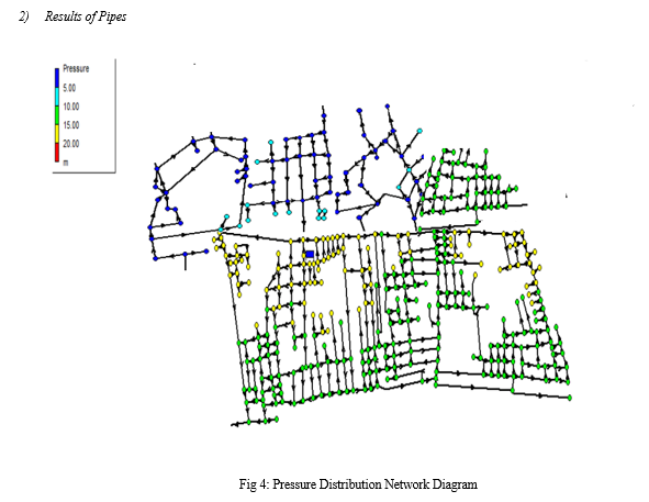
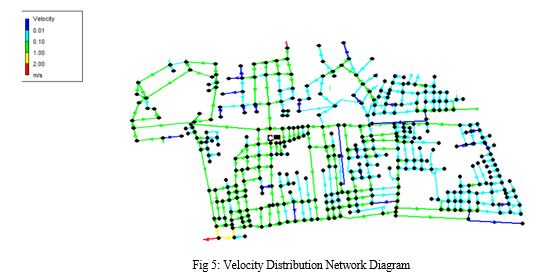
Table 4: Result of pipes
|
|
Length |
Roughness coefficient |
Flow |
Velocity |
Unit Headloss |
Friction Factor |
|
Link ID |
m |
|
LPS |
m/s |
|
|
|
Pipe p1 |
69.04 |
130 |
0.29 |
0.04 |
0.03 |
0.039 |
|
Pipe p3 |
43.76 |
130 |
1.69 |
0.22 |
0.71 |
0.03 |
|
Pipe p4 |
39.24 |
130 |
1.34 |
0.17 |
0.46 |
0.031 |
|
Pipe p5 |
45.47 |
130 |
0.12 |
0.02 |
0.01 |
0.044 |
|
Pipe p6 |
86.91 |
130 |
1.12 |
0.14 |
0.33 |
0.032 |
|
Pipe p10 |
153.27 |
130 |
1.78 |
0.23 |
0.78 |
0.03 |
|
Pipe p11 |
67.52 |
130 |
0.59 |
0.08 |
0.1 |
0.035 |
|
Pipe p14 |
87.14 |
130 |
0.04 |
0 |
0 |
0.054 |
|
Pipe p15 |
97.68 |
130 |
0.21 |
0.03 |
0.01 |
0.041 |
|
Pipe p17 |
141.26 |
130 |
0.49 |
0.06 |
0.07 |
0.036 |
|
Pipe p18 |
131.64 |
130 |
0.37 |
0.05 |
0.04 |
0.038 |
|
Pipe p19 |
70.03 |
130 |
0.45 |
0.06 |
0.06 |
0.037 |
|
Pipe p21 |
78.26 |
130 |
-0.58 |
0.07 |
0.1 |
0.035 |
|
Pipe p22 |
89.82 |
130 |
0.48 |
0.06 |
0.07 |
0.036 |
|
Pipe p23 |
82.23 |
130 |
1.75 |
0.22 |
0.76 |
0.03 |
|
Pipe p26 |
68.55 |
130 |
1.03 |
0.13 |
0.28 |
0.032 |
|
Pipe p27 |
56.87 |
130 |
0.89 |
0.11 |
0.22 |
0.033 |
|
Pipe p28 |
51.82 |
130 |
0.28 |
0.04 |
0.03 |
0.039 |
|
Pipe p29 |
92.2 |
130 |
0.04 |
0 |
0 |
0.053 |
|
Pipe p30 |
105.87 |
130 |
2.76 |
0.35 |
1.76 |
0.028 |
|
Pipe p31 |
61.14 |
130 |
0.87 |
0.11 |
0.21 |
0.033 |
|
Pipe p32 |
46.64 |
130 |
0.68 |
0.09 |
0.13 |
0.034 |
|
Pipe p33 |
121.6 |
130 |
0.95 |
0.12 |
0.24 |
0.033 |
|
Pipe p35 |
50.69 |
130 |
0.02 |
0 |
0 |
0.055 |
|
Pipe p36 |
141.7 |
130 |
1.33 |
0.17 |
0.45 |
0.031 |
|
Pipe p37 |
263 |
130 |
1.3 |
0.17 |
0.43 |
0.031 |
|
Pipe p38 |
114.2 |
130 |
0.05 |
0.01 |
0 |
0.049 |
|
Pipe p39 |
123.5 |
130 |
0.31 |
0.04 |
0.03 |
0.039 |
|
Pipe p40 |
85.47 |
130 |
1.49 |
0.19 |
0.56 |
0.031 |
|
Pipe p41 |
157.8 |
130 |
0.07 |
0.01 |
0.01 |
0.047 |
|
Pipe p45 |
104.3 |
130 |
1.99 |
0.25 |
0.96 |
0.029 |
|
Pipe p48 |
85.83 |
130 |
0.04 |
0.01 |
0 |
0.051 |
|
Pipe p49 |
214 |
130 |
0.68 |
0.09 |
0.13 |
0.034 |
|
Pipe p50 |
180 |
130 |
0.18 |
0.02 |
0.01 |
0.042 |
|
Pipe p51 |
165.19 |
130 |
0.91 |
0.12 |
0.23 |
0.033 |
|
Pipe p52 |
119.9 |
130 |
1.91 |
0.24 |
0.89 |
0.029 |
|
Pipe p54 |
195.9 |
130 |
0.67 |
0.09 |
0.13 |
0.034 |
|
Pipe p55 |
108.6 |
130 |
0.81 |
0.1 |
0.18 |
0.033 |
|
Pipe p56 |
203 |
130 |
0.48 |
0.06 |
0.07 |
0.036 |
|
Pipe p58 |
140.84 |
130 |
0.07 |
0.01 |
0.01 |
0.047 |
|
Pipe p60 |
41.92 |
130 |
0.15 |
0.02 |
0.01 |
0.043 |
|
Pipe p62 |
83.37 |
130 |
0.51 |
0.06 |
0.08 |
0.036 |
|
Pipe p63 |
45.84 |
130 |
0.56 |
0.07 |
0.09 |
0.035 |
|
Pipe p64 |
47.11 |
130 |
0.94 |
0.12 |
0.24 |
0.033 |
|
Pipe p65 |
98.7 |
130 |
1 |
0.13 |
0.27 |
0.032 |
|
Pipe p68 |
83.61 |
130 |
0.88 |
0.11 |
0.21 |
0.033 |
|
Pipe p69 |
141.9 |
130 |
0.78 |
0.1 |
0.17 |
0.034 |
|
Pipe p72 |
85.16 |
130 |
0.15 |
0.02 |
0.01 |
0.043 |
|
Pipe p73 |
49.63 |
130 |
0.02 |
0 |
0 |
0.057 |
|
Pipe p74 |
53.89 |
130 |
0.12 |
0.01 |
0 |
0.045 |
|
Pipe p75 |
17.67 |
130 |
0.09 |
0.01 |
0 |
0.046 |
|
Pipe p77 |
122.3 |
130 |
0.06 |
0.01 |
0 |
0.048 |
|
Pipe p78 |
48.13 |
130 |
0.04 |
0.01 |
0 |
0.051 |
|
Pipe p79 |
135.3 |
130 |
0.24 |
0.03 |
0.02 |
0.04 |
|
Pipe p80 |
137.83 |
130 |
0.09 |
0.02 |
0.02 |
0.044 |
|
Pipe p81 |
48.93 |
130 |
0.19 |
0.04 |
0.04 |
0.04 |
|
Pipe p82 |
85.85 |
130 |
3.86 |
0.49 |
3.27 |
0.027 |
|
Pipe p84 |
110.4 |
130 |
3.59 |
0.46 |
2.85 |
0.027 |
|
Pipe p89 |
220.46 |
130 |
3.44 |
0.44 |
2.64 |
0.027 |
|
Pipe p91 |
89.67 |
130 |
0.79 |
0.1 |
0.17 |
0.034 |
|
Pipe p92 |
66.23 |
130 |
0.85 |
0.11 |
0.2 |
0.033 |
|
Pipe p93 |
65.55 |
130 |
0.91 |
0.12 |
0.22 |
0.033 |
|
Pipe p94 |
58.11 |
130 |
0.97 |
0.12 |
0.25 |
0.033 |
|
Pipe p96 |
148.4 |
130 |
0.83 |
0.11 |
0.19 |
0.033 |
|
Pipe p97 |
61.6 |
130 |
2.38 |
0.3 |
1.33 |
0.029 |
|
Pipe p99 |
78.53 |
130 |
0.28 |
0.04 |
0.02 |
0.039 |
|
Pipe p100 |
36.88 |
130 |
0.08 |
0.02 |
0.01 |
0.046 |
|
Pipe p101 |
106.4 |
130 |
0.6 |
0.08 |
0.11 |
0.035 |
|
Pipe p103 |
95.74 |
130 |
1.36 |
0.17 |
0.47 |
0.031 |
|
Pipe p104 |
46.48 |
130 |
1.29 |
0.16 |
0.43 |
0.031 |
|
Pipe p105 |
161.2 |
130 |
0.61 |
0.08 |
0.11 |
0.035 |
|
Pipe p107 |
109.04 |
130 |
0.99 |
0.13 |
0.26 |
0.032 |
|
Pipe p108 |
75.92 |
130 |
5.19 |
0.66 |
5.66 |
0.025 |
|
Pipe p109 |
74.72 |
130 |
2.76 |
0.35 |
1.76 |
0.028 |
|
Pipe p111 |
59.56 |
130 |
13.92 |
1.77 |
35.15 |
0.022 |
|
Pipe p112 |
77.83 |
130 |
7.17 |
0.91 |
10.28 |
0.024 |
|
Pipe p117 |
97.04 |
130 |
3.79 |
0.48 |
3.16 |
0.027 |
|
Pipe p120 |
64.92 |
130 |
4.45 |
0.57 |
4.26 |
0.026 |
|
Pipe p123 |
133.9 |
130 |
0.06 |
0.01 |
0 |
0.049 |
|
Pipe p128 |
81.48 |
130 |
0.71 |
0.09 |
0.14 |
0.034 |
|
Pipe p129 |
184.97 |
130 |
0.09 |
0.01 |
0 |
0.047 |
|
Pipe p132 |
78.29 |
130 |
0.45 |
0.06 |
0.06 |
0.036 |
|
Pipe p133 |
148.52 |
130 |
0.13 |
0.02 |
0.01 |
0.044 |
|
Pipe p135 |
142.92 |
130 |
14 |
1.78 |
35.55 |
0.022 |
|
Pipe p140 |
91.23 |
130 |
0.11 |
0.01 |
0 |
0.045 |
|
Pipe p141 |
76.96 |
130 |
0.04 |
0 |
0 |
0.053 |
|
Pipe p143 |
63.05 |
130 |
0.57 |
0.07 |
0.1 |
0.035 |
|
Pipe p144 |
69.01 |
130 |
2.62 |
0.33 |
1.59 |
0.028 |
|
Pipe p147 |
25.67 |
130 |
9.75 |
1.24 |
18.19 |
0.023 |
|
Pipe p151 |
92.66 |
130 |
2.51 |
0.32 |
1.47 |
0.028 |
|
Pipe p152 |
120.3 |
130 |
1.08 |
0.14 |
0.31 |
0.032 |
|
Pipe p153 |
59.07 |
130 |
1.31 |
0.17 |
0.44 |
0.031 |
|
Pipe p154 |
63.08 |
130 |
0.03 |
0 |
0 |
0.055 |
|
Pipe p161 |
127.52 |
130 |
1.16 |
0.15 |
0.35 |
0.032 |
|
Pipe p166 |
144.3 |
130 |
0.12 |
0.02 |
0.01 |
0.045 |
|
Pipe p167 |
54.85 |
130 |
0.03 |
0.01 |
0 |
0.052 |
|
Pipe p168 |
147.5 |
130 |
0.05 |
0.01 |
0 |
0.049 |
|
Pipe p169 |
47.36 |
130 |
0.14 |
0.02 |
0.01 |
0.044 |
|
Pipe p170 |
191 |
130 |
0.43 |
0.05 |
0.06 |
0.037 |
|
Pipe p171 |
102.11 |
130 |
0.05 |
0.01 |
0 |
0.05 |
|
Pipe p175 |
150.6 |
130 |
1.15 |
0.15 |
0.35 |
0.032 |
|
Pipe p177 |
59.95 |
130 |
0.55 |
0.07 |
0.09 |
0.035 |
|
Pipe p179 |
88.07 |
130 |
0.16 |
0.02 |
0.01 |
0.042 |
|
Pipe p180 |
166.9 |
130 |
-0.05 |
0.01 |
0 |
0.05 |
|
Pipe p181 |
28.25 |
130 |
0.4 |
0.05 |
0.05 |
0.037 |
|
Pipe p182 |
97.47 |
130 |
0.04 |
0.01 |
0 |
0.051 |
|
Pipe p184 |
33.79 |
130 |
6.35 |
0.81 |
8.21 |
0.025 |
|
Pipe p185 |
30.64 |
130 |
0.54 |
0.07 |
0.09 |
0.035 |
|
Pipe p186 |
37.69 |
130 |
0.3 |
0.04 |
0.03 |
0.039 |
|
Pipe p190 |
168.74 |
130 |
4.09 |
0.52 |
3.63 |
0.026 |
|
Pipe p191 |
257.76 |
130 |
1.73 |
0.22 |
0.74 |
0.03 |
|
Pipe p193 |
27.42 |
130 |
6.36 |
0.81 |
8.23 |
0.025 |
|
Pipe p196 |
84.22 |
130 |
0.6 |
0.08 |
0.1 |
0.035 |
|
Pipe p198 |
223.3 |
130 |
0.95 |
0.12 |
0.24 |
0.033 |
|
Pipe p202 |
39.19 |
130 |
0.04 |
0.01 |
0 |
0.051 |
|
Pipe p203 |
26.31 |
130 |
-0.01 |
0 |
0 |
0 |
|
Pipe p205 |
64.83 |
130 |
2.08 |
0.27 |
1.04 |
0.029 |
|
Pipe p206 |
217.76 |
130 |
0.32 |
0.04 |
0.03 |
0.038 |
|
Pipe p209 |
236.11 |
130 |
0.1 |
0.01 |
0 |
0.045 |
|
Pipe p210 |
159.7 |
130 |
1.7 |
0.22 |
0.72 |
0.03 |
|
Pipe p211 |
160.3 |
130 |
1.56 |
0.2 |
0.61 |
0.03 |
|
Pipe p212 |
125.81 |
130 |
2.86 |
0.36 |
1.88 |
0.028 |
|
Pipe p214 |
39.34 |
130 |
2.93 |
0.37 |
1.96 |
0.028 |
|
Pipe p215 |
120.1 |
130 |
1.44 |
0.18 |
0.53 |
0.031 |
|
Pipe p216 |
249.6 |
130 |
1.16 |
0.15 |
0.35 |
0.032 |
|
Pipe p217 |
185.1 |
130 |
1.12 |
0.14 |
0.33 |
0.032 |
|
Pipe p218 |
229.9 |
130 |
0.85 |
0.11 |
0.2 |
0.033 |
|
Pipe p221 |
121.25 |
130 |
0.16 |
0.02 |
0.01 |
0.042 |
|
Pipe p226 |
364.1 |
130 |
0.16 |
0.02 |
0.01 |
0.042 |
|
Pipe p232 |
94.08 |
130 |
0.82 |
0.1 |
0.19 |
0.033 |
|
Pipe p233 |
67.56 |
130 |
0.27 |
0.03 |
0.02 |
0.039 |
|
Pipe p234 |
66.12 |
130 |
1.57 |
0.2 |
0.62 |
0.03 |
|
Pipe p237 |
44.27 |
130 |
0.29 |
0.04 |
0.03 |
0.039 |
|
Pipe p238 |
86.16 |
130 |
2.88 |
0.37 |
1.9 |
0.028 |
|
Pipe p241 |
216.53 |
130 |
0.8 |
0.1 |
0.18 |
0.034 |
|
Pipe p242 |
46.6 |
130 |
2.24 |
0.28 |
1.19 |
0.029 |
|
Pipe p245 |
167 |
130 |
1.88 |
0.24 |
0.87 |
0.03 |
|
Pipe p246 |
61.58 |
130 |
0.03 |
0 |
0 |
0.056 |
|
Pipe p247 |
48.57 |
130 |
0.66 |
0.08 |
0.12 |
0.035 |
|
Pipe p248 |
209.84 |
130 |
0.17 |
0.02 |
0.01 |
0.042 |
|
Pipe p250 |
145.9 |
130 |
0.07 |
0.01 |
0.01 |
0.047 |
|
Pipe p251 |
106.78 |
130 |
0.05 |
0.01 |
0 |
0.05 |
|
Pipe p253 |
107.96 |
130 |
0.05 |
0.01 |
0 |
0.051 |
|
Pipe p256 |
86.6 |
130 |
0.07 |
0.01 |
0.01 |
0.047 |
|
Pipe p257 |
78.24 |
130 |
0.02 |
0 |
0 |
0.056 |
|
Pipe p258 |
79.61 |
130 |
0.52 |
0.07 |
0.08 |
0.036 |
|
Pipe p259 |
125.81 |
130 |
0.06 |
0.01 |
0 |
0.048 |
|
Pipe p260 |
153.04 |
130 |
0.48 |
0.06 |
0.07 |
0.036 |
|
Pipe p262 |
68.03 |
130 |
0.63 |
0.08 |
0.11 |
0.035 |
|
Pipe p263 |
142.5 |
130 |
2.11 |
0.27 |
1.07 |
0.029 |
|
Pipe p264 |
113.4 |
130 |
0.05 |
0.01 |
0.01 |
0.049 |
|
Pipe p265 |
108.68 |
130 |
0.52 |
0.07 |
0.08 |
0.036 |
|
Pipe p266 |
89.97 |
130 |
0.21 |
0.03 |
0.02 |
0.041 |
|
Pipe p267 |
73.96 |
130 |
0.81 |
0.1 |
0.18 |
0.033 |
|
Pipe p268 |
103.6 |
130 |
4.35 |
0.55 |
4.08 |
0.026 |
|
Pipe p269 |
113.7 |
130 |
0.94 |
0.12 |
0.24 |
0.033 |
|
Pipe p270 |
86.72 |
130 |
0.04 |
0 |
0 |
0.054 |
|
Pipe p271 |
104 |
130 |
0.05 |
0.01 |
0.01 |
0.049 |
|
Pipe p272 |
200.2 |
130 |
1.77 |
0.23 |
0.77 |
0.03 |
|
Pipe p274 |
75.9 |
130 |
0.63 |
0.08 |
0.11 |
0.035 |
|
Pipe p275 |
100.5 |
130 |
0.05 |
0.01 |
0 |
0.05 |
|
Pipe p276 |
82.29 |
130 |
0.12 |
0.02 |
0.01 |
0.044 |
|
Pipe 3 |
36 |
130 |
0.27 |
0.03 |
0.02 |
0.039 |
|
Pipe 4 |
86 |
130 |
0.04 |
0.01 |
0 |
0.05 |
|
Pipe 6 |
126.12 |
130 |
0.37 |
0.05 |
0.04 |
0.038 |
|
Pipe 8 |
70.48 |
130 |
0.45 |
0.06 |
0.06 |
0.037 |
|
Pipe 10 |
32.56 |
130 |
1.06 |
0.14 |
0.3 |
0.032 |
|
Pipe 11 |
120.21 |
130 |
0.43 |
0.06 |
0.06 |
0.037 |
|
Pipe 12 |
59.93 |
130 |
1.08 |
0.14 |
0.31 |
0.032 |
|
Pipe 13 |
168.57 |
130 |
2.29 |
0.29 |
1.25 |
0.029 |
|
Pipe 14 |
61.66 |
130 |
0.61 |
0.08 |
0.11 |
0.035 |
|
Pipe 15 |
179.53 |
130 |
2.11 |
0.27 |
1.07 |
0.029 |
|
Pipe 16 |
155.14 |
130 |
0.07 |
0.01 |
0.01 |
0.047 |
|
Pipe 17 |
135.73 |
130 |
0.33 |
0.04 |
0.03 |
0.038 |
|
Pipe 20 |
81.64 |
130 |
3.66 |
0.47 |
2.97 |
0.027 |
|
Pipe 22 |
189 |
130 |
4.93 |
0.63 |
5.13 |
0.026 |
|
Pipe 23 |
155.95 |
130 |
0.07 |
0.01 |
0.01 |
0.047 |
|
Pipe 24 |
38.61 |
130 |
0.13 |
0.02 |
0.01 |
0.044 |
|
Pipe 25 |
71.79 |
130 |
0.03 |
0.01 |
0 |
0.054 |
|
Pipe 26 |
102.11 |
130 |
0.46 |
0.06 |
0.06 |
0.036 |
|
Pipe 27 |
158.57 |
130 |
0.83 |
0.11 |
0.19 |
0.033 |
|
Pipe 28 |
99.5 |
130 |
0.53 |
0.07 |
0.08 |
0.036 |
|
Pipe 29 |
130.49 |
130 |
7.79 |
0.99 |
12 |
0.024 |
|
Pipe 30 |
136.03 |
130 |
3.48 |
0.44 |
2.7 |
0.027 |
|
Pipe 31 |
210.78 |
130 |
1.52 |
0.19 |
0.58 |
0.03 |
|
Pipe 32 |
112.65 |
130 |
2.69 |
0.34 |
1.68 |
0.028 |
|
Pipe 33 |
140.6 |
130 |
11.54 |
1.47 |
24.83 |
0.023 |
|
Pipe 34 |
57.67 |
130 |
6.81 |
0.87 |
9.35 |
0.024 |
|
Pipe 35 |
24.04 |
130 |
9.39 |
1.2 |
16.97 |
0.023 |
|
Pipe 37 |
149.84 |
130 |
0.07 |
0.01 |
0.01 |
0.047 |
|
Pipe 38 |
82.88 |
130 |
1.24 |
0.16 |
0.4 |
0.031 |
|
Pipe 39 |
59.07 |
130 |
0.6 |
0.08 |
0.1 |
0.035 |
|
Pipe 40 |
151.14 |
130 |
6.26 |
0.8 |
8.01 |
0.025 |
|
Pipe 41 |
36.16 |
130 |
12.52 |
1.59 |
28.91 |
0.022 |
|
Pipe 42 |
57.13 |
130 |
9.48 |
1.21 |
17.25 |
0.023 |
|
Pipe 43 |
274.11 |
130 |
9.62 |
1.22 |
17.74 |
0.023 |
|
Pipe 46 |
48.82 |
130 |
0.95 |
0.12 |
0.24 |
0.033 |
|
Pipe 48 |
123.97 |
130 |
0.95 |
0.12 |
0.24 |
0.033 |
|
Pipe 49 |
89.49 |
130 |
0.64 |
0.08 |
0.12 |
0.035 |
|
Pipe 50 |
229.2 |
130 |
0.33 |
0.04 |
0.03 |
0.038 |
|
Pipe 18 |
187.85 |
130 |
0.33 |
0.04 |
0.03 |
0.038 |
|
Pipe 19 |
44.94 |
130 |
-0.05 |
0.01 |
0 |
0.05 |
|
Pipe 36 |
140.62 |
130 |
4.55 |
0.58 |
4.43 |
0.026 |
|
Pipe 51 |
47.25 |
130 |
4.71 |
0.6 |
4.72 |
0.026 |
|
Pipe 52 |
184.3 |
130 |
0.66 |
0.08 |
0.13 |
0.034 |
|
Pipe 53 |
128.91 |
130 |
0.09 |
0.01 |
0 |
0.047 |
|
Pipe 54 |
55.54 |
130 |
1.4 |
0.18 |
0.5 |
0.031 |
|
Pipe 55 |
159.27 |
130 |
1.61 |
0.2 |
0.64 |
0.03 |
|
Pipe 56 |
161.23 |
130 |
4.46 |
0.57 |
4.28 |
0.026 |
|
Pipe 57 |
228.07 |
130 |
0.1 |
0.01 |
0 |
0.045 |
|
Pipe 58 |
202.29 |
130 |
24.57 |
3.13 |
100.73 |
0.02 |
|
Pipe 59 |
169.26 |
130 |
2.32 |
0.3 |
1.27 |
0.029 |
|
Pipe 60 |
117.87 |
130 |
0.92 |
0.12 |
0.23 |
0.033 |
|
Pipe 61 |
116.47 |
130 |
0.16 |
0.02 |
0.01 |
0.043 |
|
Pipe 5 |
128.2 |
130 |
0.83 |
0.11 |
0.19 |
0.033 |
|
Pipe 7 |
172.99 |
130 |
0.43 |
0.06 |
0.06 |
0.037 |
|
Pipe 44 |
109.16 |
130 |
1.23 |
0.16 |
0.39 |
0.031 |
|
Pipe 45 |
108.37 |
130 |
0.37 |
0.05 |
0.04 |
0.038 |
|
Pipe 62 |
71.27 |
130 |
0.03 |
0 |
0 |
0.058 |
|
Pipe 63 |
84.87 |
130 |
0.47 |
0.06 |
0.06 |
0.036 |
|
Pipe 64 |
72.61 |
130 |
-0.61 |
0.08 |
0.11 |
0.035 |
|
Pipe 65 |
128.11 |
130 |
0.36 |
0.05 |
0.04 |
0.038 |
|
Pipe 66 |
90.86 |
130 |
0.13 |
0.02 |
0.01 |
0.044 |
|
Pipe 47 |
249.45 |
130 |
2.6 |
0.33 |
1.57 |
0.028 |
|
Pipe 67 |
124.23 |
130 |
1.36 |
0.17 |
0.47 |
0.031 |
|
Pipe 68 |
31.96 |
130 |
1.68 |
0.21 |
0.7 |
0.03 |
|
Pipe 69 |
42.19 |
130 |
1.78 |
0.23 |
0.78 |
0.03 |
|
Pipe 79 |
72.9 |
130 |
0.28 |
0.04 |
0.02 |
0.039 |
|
Pipe 80 |
61.02 |
130 |
0.03 |
0.01 |
0 |
0.054 |
|
Pipe 81 |
142.53 |
130 |
0.07 |
0.01 |
0.01 |
0.047 |
|
Pipe 82 |
20.56 |
130 |
0.19 |
0.02 |
0.01 |
0.041 |
|
Pipe 83 |
51.34 |
130 |
0.37 |
0.05 |
0.04 |
0.038 |
|
Pipe 84 |
61.81 |
130 |
8.15 |
1.04 |
13.04 |
0.024 |
|
Pipe 85 |
124.94 |
130 |
5.28 |
0.67 |
5.83 |
0.025 |
|
Pipe 86 |
56.66 |
130 |
3.25 |
0.41 |
2.38 |
0.027 |
|
Pipe 87 |
109.86 |
130 |
1.78 |
0.23 |
0.78 |
0.03 |
|
Pipe 88 |
112.04 |
130 |
2.74 |
0.35 |
1.74 |
0.028 |
|
Pipe 71 |
59.59 |
130 |
2.66 |
0.34 |
1.63 |
0.028 |
|
Pipe 72 |
121.68 |
130 |
3.37 |
0.43 |
2.54 |
0.027 |
|
Pipe 75 |
44.12 |
130 |
1.38 |
0.18 |
0.48 |
0.031 |
|
Pipe 76 |
30.52 |
130 |
2.18 |
0.28 |
1.14 |
0.029 |
|
Pipe 77 |
73.93 |
130 |
6.01 |
0.76 |
7.41 |
0.025 |
|
Pipe 78 |
55.12 |
130 |
3.33 |
0.42 |
2.49 |
0.027 |
|
Pipe 89 |
49.72 |
130 |
3.76 |
0.48 |
3.11 |
0.027 |
|
Pipe 90 |
75.18 |
130 |
11.01 |
1.4 |
22.76 |
0.023 |
|
Pipe 91 |
66.55 |
130 |
5.91 |
0.75 |
7.2 |
0.025 |
|
Pipe 92 |
47.72 |
130 |
0.56 |
0.07 |
0.09 |
0.035 |
|
Pipe 93 |
49.73 |
130 |
1.06 |
0.13 |
0.3 |
0.032 |
|
Pipe 94 |
27.01 |
130 |
1.44 |
0.18 |
0.53 |
0.031 |
|
Pipe 95 |
21.66 |
130 |
12.88 |
1.64 |
30.43 |
0.022 |
|
Pipe 96 |
150.03 |
130 |
6.43 |
0.82 |
8.41 |
0.025 |
|
Pipe 97 |
49.27 |
130 |
0.45 |
0.06 |
0.06 |
0.036 |
|
Pipe 1 |
117.36 |
130 |
24.66 |
2.18 |
41.71 |
0.021 |
|
Pipe 2 |
203.02 |
130 |
0.07 |
0.01 |
0.01 |
0.047 |
Conclusion
The project aims to design a water supply distribution system in Anakkara Grama panchayath in Palakkad District. Since there does not exist any water supply schemes the area there is a scarcity of potable water during the non-monsoon period. Hence, it has to be supplemented by a new scheme that can fulfil the requirements of providing safe potable water for the people in the area. With this in mind, we have decided to plan and design an efficient water supply scheme for the ward. The different components of the water supply scheme including Overhead water tank, and pumping units have to be effectively and economically planned and designed. The network designed has to be modelled using Epanet and checked for its viability.
References
[1] Athulya.T , Anjali. K. Ullas “Design of Water distribution network using EPANET software” International Research Journal of Engineering and Technology Volume 07, March 2020. [2] Harshan K. G , Keerthana. L. Madhu , Anjali.A “ Design of water distribution network for a small rural area using EPANET” International Journal of Research and Scientific Innovation Volume V, Issue IV, April 2018. [3] Manoj Nallanathel , B. Ramesh , Santhosh “An Over view of water distribution network design” International Journal of Pure and Applied Mathematics Volume 119 No. 17 2018. [4] R.K.Rai ,P.S Lingayat “ Analysis of water distribution network using EPANET” , 2019. [5] G. Venkata Ramanaa, Ch. V. S. S. Sudheerb B.Rajasekharc “Network analysis of water distribution system in rural areas using EPANET” 13th Computer Control for Water Industry Conference, CCWI 2015. [6] CPHEEO, (1999), “Manual on water supply and Treatment”, Ministry of Urban development, Gov. of India, New Delhi. [7] EPANET 2.0 user manual [8] Arunkumar ,M., Nethaji Mariappan, V.,E.’Water Demand analysis of municipal water supply using EPANET software’. International Journal on Applied Bioengineering, Vol. 5, No.1.2018. [9] Lewis A., Rossman. EPANET 2 USERS MANUAL Water Supply and WaterResources Division National Risk Management Research Laboratory Cincinnati, OH 4526810.
Copyright
Copyright © 2023 Haritha K, Haripriya H N, Najmu Sahidha K A, Sridhar Hariharan A. This is an open access article distributed under the Creative Commons Attribution License, which permits unrestricted use, distribution, and reproduction in any medium, provided the original work is properly cited.

Download Paper
Paper Id : IJRASET52871
Publish Date : 2023-05-23
ISSN : 2321-9653
Publisher Name : IJRASET
DOI Link : Click Here
 Submit Paper Online