

Ijraset Journal For Research in Applied Science and Engineering Technology
Development of Application for Airfoil Generation and Testing
Authors: Yash Choudahri, Mandar Karande, Shreeram Bhoite, Mrugendra Gade
DOI Link: https://doi.org/10.22214/ijraset.2023.53198
Certificate: View Certificate
Abstract
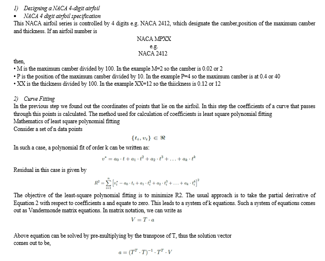
CAD automation works by utilizing tools and technology to increase the speed at which a design is completed. The CAD workflows that you set up can be carried out over and over again much like any other repetitive task in your office. This allows for multiple designs to be completed with reduced effort, freeing up valuable time for more important tasks and creativity. The application devloped automates the processes required to create an 3D part file of any airfoil.The application also provides a script to automate the next step i.e CFD analysis of the airfoil. The application is divided in 4 major parts according to the task automated. In the first section , the user can enter the parameters of desired airfoil,these parameters are then utilized by the software to create coordinates of the points that lie on airfoil. After this a curve is fitted to the airfoil points and the coefficients of the fitted curve are displayed and stored. In the section , the coefficients generated in the first section are utilized to generate CAD files of the airfoil. In the third section the software provides a python script that automates the task of carrying out the CFD simulation of airfoil. Lastly the “results” section provides a workspace to analyze the output of CFD simulation. Thus the application acts as a complete workstation for design life cycle of the airfoil.
Introduction
I. INTRODUCTION
In engineering scenarios, one may encounter complex design situations. Previously, designs were drawn on sheets and manufactured manually using old school techniques. But now, things have changed with the introduction of CAD customization and design automation.
- CAD customization is the development of support tools and technology which drives CAD automation of repetitive tasks in the design process.
- Design automation is a knowledge-based engineering approach which logically combines various engineering concepts with real time application study during product development.
In this project, design automation of airfoils has been carried out. CAD Automation applications are developed as add-ons over CAD platforms (like AutoCAD, Revit, Inventor, SolidWorks, Creo, etc). Mundane tasks that require rule-based decision making are ideal for automation. These applications intelligently extract data, apply rules, make decisions, and perform operations automatically. In this project we have used Autodesk Inventor API to provide design automation. The next functionality i.e automation of CFD simulation utilizes the python scripting functionality provided by Autodesk CFD. The application has been developed using C++ language with the help of Microsoft’s MFC library.
A. Project Identification
CAD integration enables engineers to create 3D designs instantly, removing the need for engineering consultation. In addition, CAD integration lets customers see a 3D model of their product without requiring the engineer’s input. This advancement is the next step in the manufacturing industry’s evolution. Automating the design process will allow companies to move the configuration process along faster and ensure the products are appropriately designed. And, with today’s faster processors and improved graphics, CAD automation is becoming more popular. Currently there is no software that provides automation facility for airfoil generation in CAD ecosystem. The application developed would reduce the time required for product design and analysis and streamline the entire process.
B. Project Objectives
- To develop a software that can automate CAD file generation of airfoil.
- To automate the CFD simulation of airfoil.
- To carry out data extraction from the automated CFD simulation.
C. Scope Of Work
- Visualization of airfoil based on its parameters.
- Rapid prototyping.
- Carry out a complete design study of an airfoil
- Select the optimum operating condition for a particular airfoil.
II. LITERATURE REVIEW
In the earlier chapter we looked at CAD automation, its benefits, challenges and its applications. In this chapter we will take a deep dive into the technologies used for developing the project application. Their origin, current state and usage is discussed.
A. Microsoft Foundation Class Library (MFC)
Microsoft Foundation Class Library (MFC) is a C++ object-oriented library for developing desktop applications for Windows. MFC was introduced by Microsoft in 1992 and quickly gained widespread use. While Microsoft has introduced alternative application frameworks since then, MFC remains widely used. MFC was introduced in 1992 with Microsoft’s C/C++ 7.0 compiler for use with 16-bit versions of Windows as an extremely thin object-oriented C++ wrapper for the Windows API. C++ was just beginning to replace C for development of commercial application software at the time. In an MFC program, direct Windows API calls are rarely needed. Instead, programs create objects from Microsoft Foundation Class classes and call member functions belonging to those objects. Many of those functions share their names with corresponding API functions.
B. Autodesk Inventor API
API, or Application Programming Interface, is a term used to describe the functionality exposed by an application that allows it to be used through a program.
For example, you can use Inventor’s API to write a program that will perform the same types of operations you can perform when using Inventor interactively. Having an API is important because it allows you to add functionality to Inventor that is specific to your needs. Inventor, by necessity, is a general CAD system, meaning that it’s not aimed at any specific industry or used to model only certain types of products.
By providing an API, Inventor allows you to add additional functionality and optimize repetitive operations to make it more productive for your individual needs. By providing an API, Inventor also provides you the ability to better integrate Inventor into your overall Enterprise process.
For example, you might write a program that interfaces with your company’s inventory database to obtain the current price for components so that the price shown in a part list is always up-to-date. You might also write a program that extracts data from assemblies to provide MRP systems with their required information. All of this can be done manually, but by automating it using a program you’re able to significantly increase productivity and minimize errors.
C. Autodesk CFD API
The Autodesk CFD Application Programming Interface (API) provides ways to work with Autodesk R CFD functionality that are not readily available in the user interface. The API is a platform for customization, and can significantly benefit your design process. It is very flexible, and can be used for a wide variety of tasks.
Here are a few examples of potential applications:
- Automate repetitive tasks normally performed in the user interface.
- Create custom tasks.
- Create custom results quantities.
- Output results in customized or specialized formats.
The API is based on the Python scripting language. Python has been widely accepted, and is both easy to use and flexible. Python has built-in connections with other technologies, including Microsoft Office tools such as Excel, that make it an ideal “glue language.” Autodesk CFD is distributed with Python version 2.7.
III. METHODOLODY
The development of application has been divided into four parts according to the four major components of the application.
The four individual components are -
- Sandbox - Allows 2D visualization of airfoil and generates parameters for CAD automation.
- CAD Automation - Generates 15 CAD files of the airfoils with AoA ranging from 0 to 14 degrees.
- CFD Automation - Creates 15 design studies for each individual airfoils and runs simulations for each one.
- Result Interpreter - Provides functionality to interpret the data obtained from CFD simulation. Helps in generating insights from acquired data .
A. SANDBOX
The sandbox environment allows for rapid prototyping of airfoil. The curve fitting and subsequent parameter generation takes place in this component. The component also displays the accuracy with which the curve mimics the airfoil curvature.
B. CAD Automation
This component of the application automates the steps that are required for creating an extruded profile of an airfoil. Autodesk Inventor API was selected for this task, because it has wide user base, and a complete library of functions that can automate any task needed.
The tasks that are automated in the order in which they execute are -
- Importing parameters of airfoil from a text file and saving it in the current autodesk environment.
- Creation of “sketch” object.
- Creation of the upper and lower curve of airfoil from the parameters that were imported earlier.
- Closing the sketch loop and adding fillets and other end effects required to obtain a sketch profile that can be extruded.
- Providing an angle of attack to the airfoil profile created in previous step.
- Extruding the profile.
- Creation and extrusion of an enclosure profile that will act as fluid domain for the airfoil. This is utilized in the next component i.e CFD Automation.
- Saving the file in project directory.
Above steps are repeated a total of 15 times to create 15 CAD files of airfoil ranging from AoA of 0o to AoA of 14o.
In order to initiate the execution of the above steps a button labelled “Generate Airfoil” is created and added to tools tab of Autodesk Inventor. By clicking on the “Generate Airfoil” button the above steps are initiated.
C. CFD Automation
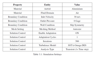
This component of the application deals with automating the general steps that are undertaken in a CFD analysis. Autodesk CFD is used for automation, since it has a built-in facility to run python scripts.
The tasks that are automated in the order in which they execute are -
- Creating a new design study.
- Applying material to the airfoil and fluid domain.
- Applying boundary conditions at inlet, outlet and the reamining walls of fluid domain.
- Meshing and configuration of solution control.
- Running the simulation.
- Calculation of lift and drag force on airfoil.
- Saving the reuslt for further analysis.
The above steps are repeated 15 times, one for each CAD file that was created by the previous component.
D. Result Interpretation
The final component of application helps in summarising and analysing the data obtained in the previously done CFD simulation.
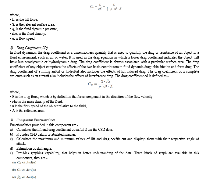
1) Lift Coefficient (CL)
In fluid dynamics, the lift coefficient (CL) is a dimensionless quantity that relates the lift generated by a lifting body to the fluid density around the body, the fluid velocity and an associated reference area. A lifting body is a foil or a complete foil-bearing body such as a fixed-wing aircraft.
IV. RESULTS
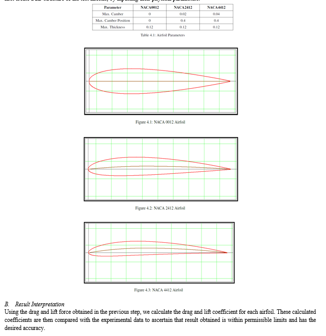
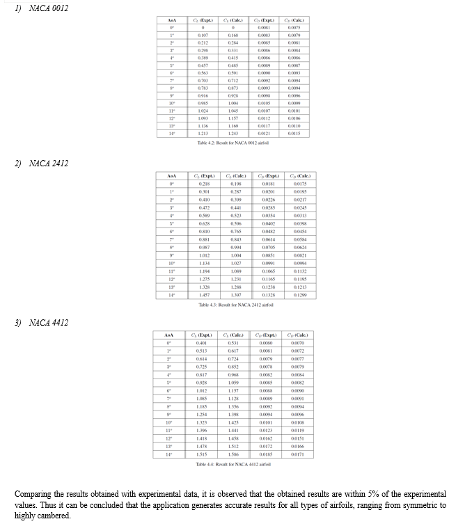
In the previous chapter we discussed about the methodology followed during the development of each individual component of the application. In this chapter we will discuss about the tests that were carried out, and the technical obstacle faced during the development of application. To validate the working of our application, we ran three tests using it. For each test we chose a different airfoil. The airfoils that were selected for testing were symmetric airfoil NACA 0012, slightly cambered airfoil NACA 2412, large cambered airfoil NACA 4412.
These airfoil had been chosen because they have been widely used and have readily available experimental data. The drag and lift coefficient obtained from the application are compared with the experimental data available and the accuracy of the obtained results is presented.
A. Input Parameters
The first step was to generate the polynomial parameter file for each airoil, which is required for CAD automation. To do so, we first create a 2D structure of the test airfoils, by inputting their physical parameters.
V. ACKNOWLEDGEMENT
We would like to express our heartfelt gratitude to all those who have contributed towards the successful completion of this mechanical project report. First and foremost, we would like to extend our sincere thanks to our project guide, Mr S.P.Mankani, for providing us with invaluable guidance, support, and motivation throughout the project. Their expertise and insightful feedback have been instrumental in shaping the report and achieving the project’s objectives. We would also like to thank the Mechanical Department of WIT Solapur for providing us with the necessary resources and facilities to carry out this project. Furthermore, we would like to express gratitude to our colleagues, friends, and family for their constant encouragement, moral support, and valuable insights, which has helped us to stay focused and motivated throughout the project. Lastly, we would like to thank all the authors, researchers, and professionals whose works I have referred to while preparing this report. Their ideas, findings, and suggestions have been a great source of inspiration and have enriched our understanding of the subject.
Conclusion
In the earlier chapter results and challenges were discussed. By the results it was found out that the application provides accurate results and helps in determining the optimal working condition of the airfoil. In this chapter, the project is concluded. 1) Rapid prototyping of airfoil has been achieved. 2) Redundant CAD and CFD tasks have been automated. 3) Tools to generate insights from results has been developed.
References
[1] Abbott, Ira Herbert; Von Doenhoff, Albert Edward (1959). Theory ofWing Sections, Including a Summary of Airfoil Data. Dover. ISBN 978-0-486-60586-9. [2] Babinsky, Holger (November 2003). “How do wings work?” (PDF). Physics Education. 38 (6): 497–503. Bibcode:2003PhyEd..38..497B. doi:10.1088/0031-9120/38/6/001. S2CID 1657792 [3] Bertin, John J.; Cummings, Russel M. (2009). Aerodynamics for Engineers (5th ed.). Pearson Prentice Hall. ISBN 978-0-13-227268 1. [4] Clancy, L.J. (1975). Aerodynamics. London: Pitman. ISBN 0-273-01120-0. [5] Halliday, David; Resnick, Robert (1988). Fundamentals of Physics (3rd ed.). JohnWiley and Sons. [6] Houghton, E. L.; Carpenter, P. W.; Collicott, Steven H.; Valentine, Daniel (2012). Aerodynamics for Engineering Students (6th ed.). Elsevier. ISBN 978-0-08-096633-5. [7] Morris, Wallace J., II (2009). A universal prediction of stall onset for airfoils at a wide range of Reynolds number flows (PhD). Harvard University. [8] Morris,Wallace J.; Rusak, Zvi (October 2013). “Stall onset on aerofoils at low to moderately high Reynolds number flows”. Journal of Fluid Mechanics. 733: 439–472. [9] Phillips, Warren F. (2004). Mechanics of Flight. John Wiley and Sons. ISBN 978-0-471- 33458-3. [10] Ramesh, Kiran; Gopalarathnam, Ashok; Granlund, Kenneth; Ol, Michael V.; Edwards, Jack R. (July 2014). “Discrete-vortex method with novel shedding criterion for unsteady aerofoil flows with intermittent leading-edge vortex shedding”. Journal of Fluid Mechanics. 751: 500–538. [11] Traub, Lance W. (24 March 2016). “Semi-Empirical Prediction of Airfoil Hysteresis”. Aerospace.
Copyright
Copyright © 2023 Yash Choudahri, Mandar Karande, Shreeram Bhoite, Mrugendra Gade. This is an open access article distributed under the Creative Commons Attribution License, which permits unrestricted use, distribution, and reproduction in any medium, provided the original work is properly cited.

Download Paper
Paper Id : IJRASET53198
Publish Date : 2023-05-28
ISSN : 2321-9653
Publisher Name : IJRASET
DOI Link : Click Here
 Submit Paper Online