

Ijraset Journal For Research in Applied Science and Engineering Technology
Development of Pipe Inspection Robot
Authors: Marala Bhavvyya Sree, Krishna Mohan VSS, Hrithik R, Hrudai HG, Nachikethan HD
DOI Link: https://doi.org/10.22214/ijraset.2022.44714
Certificate: View Certificate
Abstract
Pipelines have been a major source to transfer oil and gas from one destination to another as they are economical when compared to other transportation means. Usually metal pipes are used which can undergo corrosion, develop cavities and holes leading to leakage of fluid and develop irregularities on the inner surface. And therefore require proper periodic maintenance. The inspection of pipes is difficult as they carry toxic chemicals, fluids and most of the time have small internal diameter or bends and also usually underground which become inaccessible to humans. This brings the need to develop an inspection device.
Introduction
I. OBJECTIVES
- Reduce human interactions with dangerous pipelines.
- Accessibility in smaller pipes where humans can’t reach.
- To design a robot that can move horizontally and vertically inside the pipe and also navigate through bends.
- It should be able to move in various diameters of pipe.
- Detects the defects and transmit the location accurately.
- Make the device modular and economical.
II. PROBLEM STATEMENT
- Inspecting a pipeline often requires actively navigating into the pipes to detect the damage.
- There are small, battery-operated CCTV pipe inspection robots t hat can essentially take on the mind and function of a human employee.
- We've already covered the fact that pipe inspection robots make the job safer for employees by diving headfirst into conditions that could otherwise be perilous for human employees.
- A robot can stay inside of the pipeline for a much longer duration of time without facing additional risk. Meanwhile, a human inspector can stay safely above ground, monitoring and controlling its actions accordingly.
III. DESIGN
- The mechanism we chose for our robot is the three wheeled, wall pressed robot with individual springs for each arm.
- The three wheeled wall pressed type has 3 moving arms connected at one end to the body (rotational movement) and the other end connected to the wheels (pressed to the wall of the pipes).
- These arms are also connected to one end of the springs (somewhere on the arm) and the other end of the spring is connected to the body.
- So there are 3 arms which are connected to the body of the robot with 120 degrees to each other which hold the robot in place inside the pipe.
- Advantages over other mechanisms:
a. This mechanism was the best suited for our application because of the individual spring which is the only type which would help in turning through bends in pipe.
b. It also has lesser moving parts than the other types.
c. It can be used for a wide range of pipe diameters.
d. Better stability, control, grip inside the pipe.
IV. PARTS
- Shell: Aluminum shell housing all the electronics and acts as the core.
- Motor + gearbox: Low speed, High torque with 90 deg Bevel gear box.
- Spring: Keeps the wheels attached to the walls of the pipe.
- Arm: Aluminum arm connecting the motor and the shell.
- Camera : With night vision , helps detect the surface defects
V. CALCULATION
A. For Vertical Movement of Robot
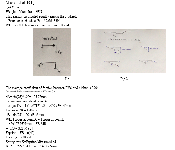
B. Fabrication
- The center shell is a hollow cylinder of OD 4 inches and thickness 3mm Aluminum pipe
- The arms are laser cut 5mm thick Al sheet into rectangles 30mm wide 310mm long
- 3 arms are placed perpendicular to the shell and at 1200 w.r.t to each other
- The arms are connected to the center shell by means of pivot arm bearings
- The motor gear box shaft is coupled with the wheel and mounted on the arm free end
- A compression spring of 38 N/m stiffness connects the center shell to the center of the arm.
- This spring is bolted on both the ends.
- This whole setup is joint to a mirror setup by means of a UV joint.
- All the electrical components including the camera and controller are housed inside the center shell.
- A 1800 view night vision camera is mounted in front of the center shell.
C. Electric Circuit
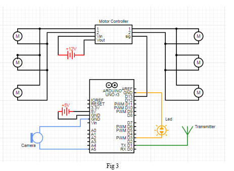
The brain of the system is the Arduino Uno which stores all the codes and works along with other modules. The three motors on each arm work simultaneously and are driven by a motor controller with which the speed and the direction of the motor can be controlled.
The LED lights for visibility are connected to the digital pins of the board.
VGA CMOS Camera Image Sensor Module is used to detect the defects on the walls of the pipes and the data is transmitted to the on site engineer for further processing .The entire system is powered by a 12V 10000 mAh lithium Ion Battery and has a duration of approximately one hour per full charge.
VI. METHODOLOGY
To execute the project, the entire timeline was divided into five phases- starting with the
- Research Phase: It involves research on the mechanism that can be incorporated for the robot to adjust to the various diameters of the pipes. Along with it, the mechanical parts and the sensors required for the project.
- Design Phase: Starts with the design of all the required parts and checking their assembly and mounting in the entire model. With the entire model, the animation of the movement of the robot inside the pipe with its adaptation to the varying diameter will be performed.
- Fabrication: The selection of the material happens side by side along with the design. Later the materials are acquired and the fabrication of the model will be done.
- Testing: Once the robot is designed, it will be tested inside different pipe materials to check its accuracy and reliability.
- Improvisation: With the data from testing, the necessary improvements will be done on the design and the testing will be carried out again.
VII. RESULTS AND DISCUSSION:
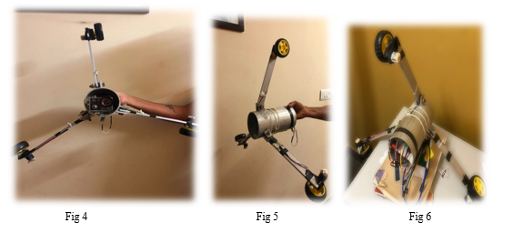
A. Mechanical Design
The team was able to design the different components of the robot and assemble it on Autodesk fusion 360.
- The robot consists of a shell made of aluminum tube cut to length and the flanges for the arm and the spring are later TIG welded to the shell.
- The arms are laser cut from a 5mm Aluminum sheet. One end of the arm is attached to the shell and the other carries the motor and the wheels.
- The wheels are 100 mm in OD and are driven by a 1000 rpm 34.3N-cm motor which gives a high torque of the robot to move in different surface conditions.
- A 90 degree bevel gear is used to change the axis of rotation by 90 degrees for the wheels. The current gear ratio is 1:1 but might change when implemented based on the torque and speed requirements.
- Finally a compression spring attached to the arm and the shell that allows the robot to self adjust to the varying diameters of the pipes.
B. Electrical Design
The team will be able to design and implement all the electronics on the robot with the help of an arduino UNO. The Arduino UNO being an open source helps to code and debug easily.
The major task will be to implement the camera module and the transmission of the data to the onsite engineers. For the transmission, there are 2 options- a) Bluetooth - which has good connectivity over short distance and is much cheaper b) ESP8266 wifi module - which has a wider range and can also be connected the internet for remote inspection.
C. Integration of Mechanical and Electrical Components
The integration will require basic wiring and following the standard operational procedures to implement the system. The major task will be to protect the electronics for the saline water to prevent short circuiting and at the same time make it easy to repair and replace.
VIII. FUTURE SCOPE
- Currently the robot is in the design and sourcing phase and post pandemic we will be working on the manufacturing of our IN-PIPE-INSPECTION ROBOT.
- Later the testing and fine tuning of our robot in various conditions will be carried out.
- Currently ,the robot uses a camera to transmit live footage to the inspector who detects the defects in the pipes. This process can be automated by programming the camera for image recognition and help the system learn on its own through AI.
- With advancement in technology, the sensing methods can be upgraded, made smaller and compact, improving the range of defects and pipes that can be inspected.
Conclusion
A. After our research on the various mechanisms, the team finalised on the wall pressed, three arm individual spring mechanism .The springs give independent movement to the arms which help in navigating bends and adapt to the varying diameter. B. In total, the robot has two identical structures with three arms, springs, gearbox and motors each and is attached with a Universal joint. C. The robot detects the surface defects with a wide angle camera (with night vision) and transmits the live footage to the inspector outside. The camera pivots about a point powered servo motors to cover the range of the hemisphere and is controlled by the inspector with a joystick.
References
[1] Material Selection for Water Pipes by the Multi-Objective Decision-Making Method: The Case of Alternative Materials for PVC Pipes; Emmanuel K. Arthur1, Emmanuel Gikunoo1, Frank O. Agyemang1, Salifu T.Azeko2, Anthony Andrews1, Abigail Twenewaa1; https://www.researchgate.net/publication/341120909_Material_Selection_for_Water_Pipes_by_the_Multi-Objective_Decision-Making_Method_The_Case_of_Alternative_Materials_for_PVC_Pipeshttps://www.researchgate.net/publication/341120909_Material_Selection_for_Water_Pipes_by_the_Multi-Objective_Decision-Making_Method_The_Case_of_Alternative_Materials_for_PVC_Pipes [2] Pipe Materials in Transmission Mains; C.R.W. Kayombo; https://www.ircwash.org/sites/default/files/223-81PI.pdfhttps://www.ircwash.org/sites/default/files/223-81PI.pdf [3] Detecting cracks in pipelines using Ultrascan; N.l.Uzelac, H. H. Willems and 0. A. Barbian; https://lib.dr.iastate.edu/cgi/viewcontent.cgi?referer=https://www.google.com/&httpsredir=1&article=4045&context=qndehttps://lib.dr.iastate.edu/cgi/viewcontent.cgi?referer=https://www.google.com/&httpsredir=1&article=4045&context=qnde [4] Crack management in vintage pipes; Brent Vyvial;https://www.stress.com/crack-management-in-vintage-pipelines/https://www.stress.com/crack-management-in-vintage-pipelines/ [5] Pipeline corrosion and cracking and the associated calibration consideration for same side sizing application; Ginzel, R.K. &Kanters, W.A;https://www.ndt.net/article/v07n07/ginzel_r/ginzel_r.htmhttps://www.ndt.net/article/v07n07/ginzel_r/ginzel_r.htm [6] Oil and gas pipeline design, maintenance and repair; Dr. Abdel-Alim Hashem;http://www.eng.cu.edu.eg/users/aelsayed/Part 4 PIPELINE COMPONENTS.pdfhttp://www.eng.cu.edu.eg/users/aelsayed/Part%204%20PIPELINE%20COMPONENTS.pdf [7] Impact loading and transient response of pipes transporting gas or liquid; Roslina Mohammad; https://digital.library.adelaide.edu.au/dspace/bitstream/2440/95628/3/02whole.pdfhttps://digital.library.adelaide.edu.au/dspace/bitstream/2440/95628/3/02whole.pdf [8] An IVTIFN–TOPSIS Based Computational Approach for Pipe Materials Selection; Rui Zhao , Ya Huang , Yang Yu and Sidai Guo; https://res.mdpi.com/d_attachment/applsci/applsci-09-05457/article_deploy/applsci-09-05457.pdfhttps://res.mdpi.com/d_attachment/applsci/applsci-09-05457/article_deploy/applsci-09-05457.pdf [9] Corrosion problems during oil and gas production and its mitigation; Lekan Taofeek Popoola, Alhaji Shehu Grema , Ganiyu Kayode Latinwo , BabaganaGutti and AdeboriSaheed Balogun;https://link.springer.com/content/pdf/10.1186/2228-5547-4-35.pdfhttps://link.springer.com/content/pdf/10.1186/2228-5547-4-35.pdf [10] Material property relationships for pipeline steels and the potential for application of NDE; Lucinda smart, leonard j bond;https://aip.scitation.org/doi/pdf/10.1063/1.4940620https://aip.scitation.org/doi/pdf/10.1063/1.4940620 [11] Corrosion control in oil and gas pipelines; Jamil Enani; https://www.ijser.org/researchpaper/Corrosion-control-in-oil-and-gas-pipelines.pdfhttps://www.ijser.org/researchpaper/Corrosion-control-in-oil-and-gas-pipelines.pdf [12] Characterization of Pipeline Defects; Thomas J. Picciott; https://primis.phmsa.dot.gov/rd/mtgs/020707/TomPicciott.pdfhttps://primis.phmsa.dot.gov/rd/mtgs/020707/TomPicciott.pdf [13] Study of pipe inspection and cleaning robot; Ahireakash, Kumkarsachin, Waghchaure Atul and V.S.Gavli;http://data.conferenceworld.in/ICETEMR/P737-7473.pdfhttp://data.conferenceworld.in/ICETEMR/P737-7473.pdf [14] A survey on coverage path planning for robotics; EnricGalceran, Marc Carreras; https://www.sciencedirect.com/science/article/abs/pii/S092188901300167X [15] Depth estimation of steel cracks using laser and image processing techniques;https://www.sciencedirect.com/science/article/pii/S1110016818300693 - !Hesham M.Shehata, Yasser S.Mohamed,https://www.sciencedirect.com/science/article/pii/S1110016818300693 - !Mohamed Abdellati, Taher H.Awad; khttps://www.sciencedirect.com/science/article/pii/S1110016818300693#:~:text=Measurement%20of%20maximum%20actual%20depths,VK%2DX100)%20laser%20microscope.&text=Measured%20and%20calculated%20depths%20are,6.13%25%20and%2028.22%25%20respectively. [16] A Study on Crack Depth Measurement in Steel Structures Using Image-Based Intensity Differences; Ju-Yeong Jung, Hyuk-Jin Yoon and Hyun-Woo Cho;https://www.hindawi.com/journals/ace/2018/75309https://www.hindawi.com/journals/ace/2018/75309 [17] Development of In-pipe Inspection Robot; IszmirNazmi Ismail, AdzlyAnuar, Khairul Salleh Mohamed Sahari, MohdZafriBaharuddin, Muhammad Fairuz Abd Jalal and Juniza Md Saad;https://www.researchgate.net/publication/256847866_Development_of_In-pipe_Inspection_Robot_A_Reviewhttps://www.researchgate.net/publication/256847866_Development_of_In-pipe_Inspection_Robot_A_Review [18] Design and Testing of Pipeline Inspection Robot; Hanaa Said Salim Al-Hajry and G.R. Rameshkumar;http://www.ijeir.org/administrator/components/com_jresearch/files/publications/IJEIR_606_Final.pdfhttp://www.ijeir.org/administrator/components/com_jresearch/files/publications/IJEIR_606_Final.pdf [19] Pipeline Inspection for Corrosion using a Mobile Robotic Systems; Itseoritseagba Godwin, Donald O Ene, Ijibike Udo, Phileas E Awe, EfekiluoBarthelomew, Douglas Oghenefegor, Godwin Etebenumeh, BakpaOghenenyerovwo, Godswill Ofualagba and O\'tega A Ejofodomi;https://vibgyorpublishers.org/content/ijre/fulltext.php?aid=ijre-1-001https://vibgyorpublishers.org/content/ijre/fulltext.php?aid=ijre-1-001 [20] Pipe Flow Problems; Unknown author;http://www.egyankosh.ac.in/bitstream/123456789/29371/1/Unit-12.pdfhttp://www.egyankosh.ac.in/bitstream/123456789/29371/1/Unit-12.pdf
Copyright
Copyright © 2022 Marala Bhavvyya Sree, Krishna Mohan VSS, Hrithik R, Hrudai HG, Nachikethan HD. This is an open access article distributed under the Creative Commons Attribution License, which permits unrestricted use, distribution, and reproduction in any medium, provided the original work is properly cited.

Download Paper
Paper Id : IJRASET44714
Publish Date : 2022-06-22
ISSN : 2321-9653
Publisher Name : IJRASET
DOI Link : Click Here
 Submit Paper Online