

Ijraset Journal For Research in Applied Science and Engineering Technology
Electrical Vehicle to Vehicle Charging Without Charging Station
Authors: Dr. Sunil Kumar Chaudhary, Prem Shankar Pachauri, Ani seth, Dheeraj Kumar Yadav, Shubham Singh, Atul Singh
DOI Link: https://doi.org/10.22214/ijraset.2022.41114
Certificate: View Certificate
Abstract
Electrical vehicles will be the next biggest revolution in vehicle industries. The present infrastructure, which is currently in use has lot of drawbacks and shortcomings which needed to be overcome. The biggest problem is lack of charging infrastructure for electrical vehicle and so electrical vehicle users always have this charging anxiety in their mind while picking up electrical vehicle for some purpose, so this paper will provide an incredible solution to this problem by implementing a V2V charging infrastructure without bringing a charging station in to the picture. This V2V charging infrastructure will use conducting charging as medium of charging.
Introduction
I. INTRODUCTION
All electrical vehicles need batteries as a fuel in order to run them, batteries play a very vital role in development of electrical vehicle as a reliable source of transportation. Since there are various reasons why whole world is promoting the use of electrical vehicle some the reasons are global warming, ice melting, polluting, eradication of non-renewable sources of energy, we all know indiscriminating use of non-renewable energy sources will one day leave us in greatest turmoil of all the times. Steps have already been taken by people and organizations across the globe to promote use of electrical vehicles but in the present infrastructure there are many shortcomings which needed to be overcome in order to make electrical vehicle more reliable and efficient. Our paper has brought a whole new different concept which will remove dependency of electrical vehicle on charging stations. In our project we have developed vehicle to vehicle charging infrastructure without bringing charging station in to the picture. In our project we will charge one electrical vehicle from another electrical vehicle i.e. one electrical vehicle will act as source of charge from which another electrical vehicle will be charged. The source car can be charged from grid, home, organizations. Etc. the medium of charging one electrical vehicle from another in purely conductive, we can use simple USB charging cable to transfer charge bidirectional. The main advantages of this infrastructure are independency from charging station, charging can be done on road at any time, in case of emergency this infrastructure will be boon for users. This infrastructure is very much practical and can be used for different wheelers. The best thing about this infrastructure is it will eventually alleviate range anxiety from the minds of electrical vehicle users
II. METHODOLOGY
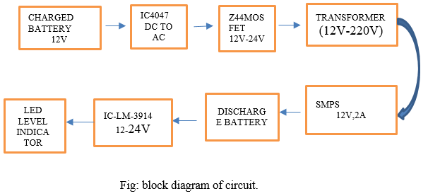
Following steps describes working and use of each component used in device.
- Step 1: The 12v battery is fully charged with dc supply or it can be charged with any grid, home, building etc. in order to remove ripple effect we have used buck boost converter to provide smoothening effect to the voltage waveform. In parallel to the 12v battery the capacitor of 1000µF is connected to avoid any kind of interruption.
- Step 2: IC CD4047 used for converting DC to AC signal, it is a multi vibrator also used in various application like frequency multipliers, time delay etc. this IC has total of 14 pins out of which 4, 5, 6, 7 are grounded and 1, 2, 3 are responsible to vary the frequency in output. The output is available at pins 10,11. When pin gives high output other will give low output and vice-versa.
- Step 3: IRFZ44 is N channel mosfet with low threshold voltage of 4v at which the mosfet will start conducting. This mosfet possess high switching capability which makes it ideal choice for our project at the output of mosfet we will get 12 v AC so by using step up transformer the voltage can be step up to 220 v.
- Step 4: Instead of giving 220 v directly to smps we have used bridged rectifier in between transformer and smps this simply improves lifetime of smps, also a capacitor of 100µF is also connected to smps. Now the with 12v output of smps another vehicle can be easily charged.
- Step 5: The discharged battery is connected through smps and a battery level indicator is also connected which will show how much battery is charged or discharged.
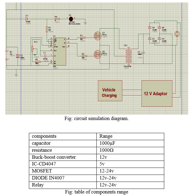
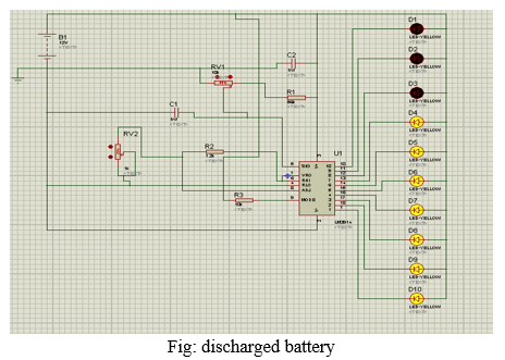
III. CIRCUIT DIAGRAM
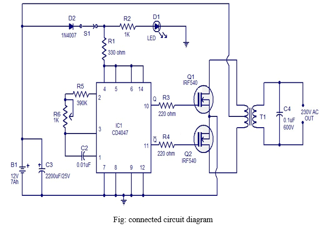
Simulation of above circuit has been performed on proteus simulation software and simulation of the above circuit helped us to choose perfect range for the component we have used in the circuit. Simulation has been done multiple times for multiple values of the components. And those values are selected which have shown best results. This whole circuit is connected to the battery level indicator and simulation of battery level indicator is also performed which have shown us the desired results which we have expected for our project. Different LEDs are used to indicate the level of battery charging with the help of battery level indicator we can easily able to predict how much our battery is charged or discharged.
IV. RESULT AND OUTPUT
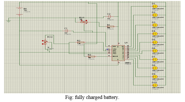
With help of battery level simulation indicator, we can easily understand how battery is charged and discharged. Level of LED indicate the level of battery by adjusting the resistance we can increase or decrease the charging time of battery that’s why correct use of resistance is very important to obtain optimal results.
Following simulation results will indicate the battery level for different values of resistance.
- Charge Function: Input AC voltage, which is supplied by the EVSE through a charging cable, is converted into DC voltage by a boost power factor correction (PFC)*2 circuit. Then, an H-bridge*3 circuit converts the DC voltage into high-frequency AC voltage. A high-frequency transformer regulates transformation and insulation. Rectifier and smoothing circuits convert the high-frequency AC voltage into DC volt age and charge the battery. To follow output indications from the charge control ECU, the bidirectional charger supports various control modes, such as constant power (CP) mode, constant current (CC) mode and constant voltage(CV) mode.
- Discharge Funtion: Input DC voltage, supplied from the on-board battery, is converted into high-frequency AC voltage by a boost H-bridge circuit. Then, a high-frequency transformer, rectifier and smoothing circuits convert the high frequency AC voltage into DC voltage. The inverter circuit, which converts the DC voltage into AC voltage, supports both a self-sustained operation (V2L).
- Battery Charger
a. USB Based: Since the Universal Serial Bus specification provides for a five-volt power supply, it's possible to use a USB cable as a power source for recharging batteries. Products based on this approach include chargers designed to charge standard NiMH cells, and custom NiMH batteries with built-in USB plugs and circuitry which eliminate the need for a separate charger. Moixa Energy patented a design of batteries, branded USBCELL, that incorporate their own USB chargers internally, complete with their own plugs. In the currently available AA battery design, the positive end of the battery doubles as a flip-cap for the built-in USB plug.
b. Charge Rate: This is often denoted as C and signifies a charge or discharge rate equal to the capacity of a battery divided by 1 hour. For example, C for a 1600 mAh battery would be 1600 mA (or
c. Prolonging of Battery: A short circuit (connecting the output terminals together) does not usually damage a simple battery charger. For that reason, it is a suitable source of DC voltage for experimentation. It may, however, require an external capacitor to be connected across its output terminals in order to "smooth" the voltage sufficiently, which may be thought of as a DC voltage plus a "ripple" voltage added to it. To see the difference between connecting and not connecting a capacitor, connect also an oscilloscope across the output terminals. Note that there may be an internal resistance connected to limit the short circuit current, and the value of that internal resistance may have to be taken into consideration in experiments.
d. Battery-level Indicator: Normally, in mobile phones, the battery level is shown in dot or bar form. This lets you easily recognize the battery level. Here we present a circuit that lets you know the battery level of a device from the number of LED s that are glowing. It uses ten LED s in all. So if three LED glow, it indicates battery capacity of 30 per cent. Unlike in mobile phones where the battery-level indicator function is integrated with other functions, here only one comparator IC (LM3914) does it all.The circuit derives the power supply for its operation from the battery of the device itself. It uses ten LED wired in a 10-dot mode. The use of different colored LED makes it easier to recognition the voltage level on the basis of the calibration made. Red LED (LED1 through LED3) indicate battery capacity of less than 40 per cent. Orange LED (LED4 through LED6) indicate battery capacity of 40 to less than 70 per cent and green LED (LED7 through LED10) indicate battery capacity of 70 to under 100 per cent. The brightness of the LED can be adjusted by varying the value of preset VR2 between pins 6 and 7.
V. THE RESULT
By using bidirectional l charging both the vehicles can be charged without any dependency on charging stations which eventually saves lots of time and money and also aids to achieve sustainable development as promised by India in cop 26 Glasgow. Smart charging of vehicle also boosts overall range of vehicles. Buck boost converter will be used as mediator to compensate losses which happen while bidirectional flow of charge.
VI. FUTURE WORK
By using IoT and artificial intelligence we can make this device smarter and intelligence. Artificial intelligence safety applications like predictive maintenance of equipment, driver behavior monitoring, and vehicle security.
Conclusion
Bidirectional v2v charging is panacea to many problems in present infrastructure by using conductive bidirectional charging we can provide boost to this industry. Moreover, bidirectional V2V charging is very handy in case of exigency or emergency.
References
[1] X. Mou, R. Zhao and D. T. Gladwin, \"Vehicle-to-Vehicle charging system fundamental and design comparison,\" 2019 IEEE International Conference on Industrial Technology (ICIT), 2019, pp. 1628-1633, doi: 10.1109/ICIT.2019.8755057. [2] J. Liu, J. Zhang and D. Zhang, \"Research on Electric Vehicle Charging Methods and Business Model,\" 2015 8th International Conference on u- and e-Service, Science and Technology (UNESST), 2015, pp. 26-29, doi: 10.1109/UNESST.2015.14. [3] K. M. Tan, V. K. Ramachandaramurthy and J. Y. Yong, \"Bidirectional battery charger for electric vehicle,\" 2014 IEEE Innovative Smart Grid Technologies - Asia (ISGT ASIA), 2014, pp. 406-411, doi: 10.1109/ISGT-Asia.2014.6873826 [4] V. K. Singh, Y. Sahu, P. K. Mishra, P. Tiwari and R. Maurya, \"CHARGING OF ELECTRIC VEHICLES BATTERY USING BIDIRECTIONAL CONVERTER,\" 2020 International Conference on Electrical and Electronics Engineering (ICE3), 2020, pp. 82-88, doi: 10.1109/ICE348803.2020.9122843. [5] M. P. Puentes and G. Ramos, \"Level 2 bidirectional charger for small electric vehicles: Topologies comparison,\" 2013 Workshop on Power Electronics and Power Quality Applications (PEPQA), 2013, pp. 1-5, doi: 10.1109/PEPQA.2013.6614968.. [6] J. Yuan, L. Dorn-Gomba, A. D. Callegaro, J. Reimers and A. Emadi, \"A Review of Bidirectional On-Board Chargers for Electric Vehicles,\" in IEEE Access, vol. 9, pp. 51501-51518, 2021, doi: 10.1109/ACCESS.2021.3069448. [7] P. Mahure, R. K. Keshri, R. Abhyankar and G. Buja, \"Bidirectional Conductive Charging of Electric Vehicles for V2V Energy Exchange,\" IECON 2020 The 46th Annual Conference of the IEEE Industrial Electronics Society, 2020, pp. 2011-2016,doi: 10.1109/IECON43393.2020.9255386. [8] M. Eull, L. Zhou, M. Jahnes and M. Preindl, \"Bidirectional Non-Isolated Fast Charger Integrated in the Electric Vehicle Traction Drivetrain,\" in IEEE Transactions on Transportation Electrification,doi:10.1109/TTE.2021.3124936. [9] F. Asakura, N. Kimura and Y. Hayashi, \"Loss Analysis of Hybrid Electric Vehicle Inverters,\" 2019 10th International Conference on Power Electronics and ECCE Asia (ICPE 2019 - ECCE Asia), 2019, pp. 1473-1480, doi:10.23919/ICPE2019-ECCEAsia42246.2019.8796962 [10] H. C. Güldorum, ?. ?engör and O. Erdinç, \"Charging Management System for Electric Vehicles considering Vehicle-to-Vehicle (V2V) Concept,\" 2020 12th International Conference on Electrical and Electronics Engineering (ELECO), 2020, pp. 188-192, doi: 10.1109/ELECO51834.2020.00050. [11] A. Wijesekera and P. Binduhewa, \"Design of a Small Electric Vehicle Charger with Multi-Ports,\" 2018 2nd International Conference On Electrical Engineering (EECon), 2018, pp. 8-13, doi: 10.1109/EECon.2018.8541014 [12] J. Buys et al., \"Bidirectional Universal Converter Transformer Design for Electric Vehicle Onboard Charging,\" 2020 IEEE Energy Conversion Congress and Exposition (ECCE), 2020, pp. 4094-4096, doi: 10.1109/ECCE44975.2020.9235905. [13] L. Nikitha, L. Anil, A. Tripathi and S. Nagesh, \"Effect of electrical vehicle charging on power quality,\" 2017 International Conference on Circuit ,Power and Computing Technologies (ICCPCT), 2017, pp. 1-6, doi: 10.1109/ICCPCT.2017.8074344. [14] S. A. Lupu, A. A. Dinu and C. M. Gheorghe, \"System for Managing the Electric Vehicle Charging Stations. An Educational Platform,\" 2021 12th International Symposium on Advanced Topics in Electrical Engineering (ATEE), 2021, pp. 1-5, doi: 10.1109/ATEE52255.2021.9425080. [15] X. Mou, R. Zhao and D. T. Gladwin, \"Vehicle to Vehicle Charging (V2V) Bases on Wireless Power Transfer Technology,\" IECON 2018 - 44th Annual Conference of the IEEE Industrial Electronics Society, 2018, pp. 4862-4867,doi:10.1109/IECON.2018.8592888 [16] J. Sears, D. Roberts and K. Glitman, \"A comparison of electric vehicle Level 1 and Level 2 charging efficiency,\" 2014 IEEE Conference on Technologies for Sustainability (SusTech), 2014, pp. 255-258,doi:10.1109/SusTech.2014.704623.
Copyright
Copyright © 2022 Dr. Sunil Kumar Chaudhary, Prem Shankar Pachauri, Ani seth, Dheeraj Kumar Yadav, Shubham Singh, Atul Singh. This is an open access article distributed under the Creative Commons Attribution License, which permits unrestricted use, distribution, and reproduction in any medium, provided the original work is properly cited.

Download Paper
Paper Id : IJRASET41114
Publish Date : 2022-03-30
ISSN : 2321-9653
Publisher Name : IJRASET
DOI Link : Click Here
 Submit Paper Online