

Ijraset Journal For Research in Applied Science and Engineering Technology
Estimation of Automotive li-ion Battery Parameters Using MATLAB Simulink
Authors: Pawaskar Gayatri Nilesh , Shaikh Anas Ahmed Atique , Saiyed Aman Nisar , Samal Deepak Kumar Ratnakar , Dr. Anup Narayan Chawan
DOI Link: https://doi.org/10.22214/ijraset.2022.47867
Certificate: View Certificate
Abstract
Electric Vehicles have seen a great boon of improvement over the last couple of decades. The evolution of these vehicles has led to greater changes in battery packs being utilized for the improvement of the performance of EVs, this has created a need for greater Battery Management Systems. Battery monitoring is vital for most Electric Vehicles (EVs) for greater executions and safety of the occupants. The project presented in this book focuses on estimation of Lithium Ion Battery Parameters using MATLAB Simulink software for 2022-Nissan LEAF Electric Vehicle. Battery management system (BMS) is an integral part of the electric vehicle (EV) and the hybrid electric vehicle (HEV). The BMS performs the tasks by integrating one or more of the functions, such as sampling the voltages of the battery cells and the temperatures in the battery module, sampling the current of the battery as well as cells balancing and determining the state of charge (SOC). In this project the research of the cells voltage sampling , battery temperature sampling, battery voltage sampling, battery current sampling and battery pack balancing will be discussed. The method of sampling cell voltage, battery temperature and cell balancing using a special logic circuit in MATLAB Simulink will be presented. This method resolves the problems of sampling cell parameters and balancing in the li-ion battery, which has hundreds of cells. We will be discussing two systems, in which one focuses on the Nissan LEAF battery pack parameters, and the other will focus on Nissan LEAF cell parameters.
Introduction
I. INTRODUCTION
A. Overview
BATTERIES are the most common electrical energy storage devices in EVs. The performance of a battery when it is connected to a load, or a source is based on the chemical reactions inside the battery. The chemicals degrade with time and usage that reflect the gradual reduction in the energy storage capacity of the battery.[23] The battery depreciation process needs to be reduced by conditioning the battery in a suitable manner by controlling its charging and discharging profile, even under various load conditions.[5] In general, the battery lifetime will be diminished when the battery is operated under a wide range of thermal conditions and frequent charge and deep discharge cycles, particularly at high-pulse current conditions. Batteries are safe, despite reports of explosion or failure, when used with a power-conditioning system that incorporates safety features and automatic shutdown.[2]
Conventional low-cost battery chargers employ few protective features intended for that battery, thus lacking flexibility and full-fledged protection.[23] Hence, BMS, which is flexible to protect batteries of different types and can provide all the safety features, has been the topic of our project. One of the important parameters that are required to ensure safe charging and discharging is SOC.[2] SOC is defined as the present capacity of the battery expressed in terms of its rated capacity.[4] SOC provides the current state of the battery and enables batteries to safely be charged and discharged at a level suitable for battery life enhancement. However, measuring SOC is not direct, because it involves the measurement of battery voltage, current, temperature, and other information that pertains to the battery under consideration.[3]
Accurate estimation of SOC prevents battery damage or rapid aging by avoiding unsuitable overcharge and over discharge.[5] The conventional SOC estimation using the Coulomb counting method suffers from error accumulation glitch, leading to inaccurate estimation. In addition, the finite battery efficiency and the chemical reaction that takes place during charge and discharge conditions cause temperature rise, which influences SOC estimation.[4] Therefore, accurate algorithms are needed to model the battery for SOC estimation.[2] In EVs, the number of batteries is connected in series-parallel combination to match the load requirement. Due to manufacturing procedures, not all batteries simultaneously attain full voltage during charging.[5]
This condition results in voltage imbalance among different batteries and, consequently, lower capacity from the entire battery string.[11] Therefore, a cell with 100% SOC may not necessarily indicate the actual SOC.[3] Therefore, accurate calculation of SOC must be accompanied by a continuous monitoring of the actual capacity of the cell with several measurements of the cells to reflect the actual and practical capability of the cell to fit the different road conditions and driving patterns of EVs.[4]
Determining the SOH of a battery adaptively is important for optimal energy management and on-board diagnostics for efficient operation of HEVs and PHEVs. Generally, SOH is used to deduce how well the battery system is functioning relative to its nominal (rated) and end (failed) states.[4] The SOH reflects the general condition of a battery and its ability to deliver the specified performance in comparison with a new battery.[8] It considers factors such as charge acceptance, internal resistance, voltage, and self-discharge. Hence, knowing changes in the SOH with time may be viewed as enabling one to assess the increase in irreversible losses that is inherent in the aging of batteries.[18]
In practice, SOH is estimated from a single measurement of either the cell impedance or the cell conductance.[2] In pursuit of accuracy, others advocate measuring several cell parameters, all of which vary with the age of the battery and estimate SOH from a combination of these factors.[14] As with all lithium-ion batteries, electric vehicle batteries may degrade over long periods of time, especially if they are frequently charged to 100%; however, this may take at least several years before being noticeable. A typical warranty is 8 years or 100 thousand miles, but they usually last much longer, perhaps 15 to 20 years in the car and then more years in another use.[8]
B. Principle
The principle of the BMS is to protect the battery system from damage, to predict and increase battery life, and to maintain the battery system in an accurate and reliable operational condition. The BMS performs several tasks, such as measuring the system voltage, current and temperature (VIT), the cells’ state of charge (SoC), state of health (SoH) and remaining useful life (RUL) determination, protecting the cells, thermal management, controlling the charge/discharge procedure, monitoring, storing historical data, data acquisition, communication with on-board and off-board modules (may be charger), and most importantly is the cell balancing.
Battery pack designs for Electric Vehicles (EVs) are complex and vary widely by manufacturer and specific application. However, they all incorporate a combination of several simple mechanical and electrical component systems which perform the basic required functions of the pack.
The actual battery cells can have different chemistry, physical shapes, and sizes as preferred by various pack manufacturers. Battery packs will always incorporate many discrete cells connected in series and parallel to achieve the total voltage and current requirements of the pack. Battery packs for all electric drive EVs can contain several hundred individual cells. Each cell has a nominal voltage of 3-4 volts, depending on its chemical composition. To assist in manufacturing and assembly, the large stack of cells is typically grouped into smaller stacks called modules. Several of these modules will be placed into a single pack. Within each module the cells are welded together to complete the electrical path for current flow. Modules can also incorporate cooling mechanisms, temperature monitors, and other devices. Modules must remain within a specific temperature range for optimal performance. In most cases, modules also allow for monitoring the voltage produced by each battery cell in the stack by using a Battery Management System (BMS).
The battery pack also contains a variety of temperature, voltage, and current sensors. Collection of data from the pack sensors and activation of the pack relays are accomplished by the pack's Battery Monitoring Unit (BMU) or Battery Management System (BMS). The BMS is also responsible for communications with the vehicle outside the battery pack.
C. Environmental Aspect
With the increasing focus on environmental protection and energy conservation, new energy vehicles (NEVs) have been extensively investigated during the past decade. Among various types of NEVs, hybrid electric vehicles (HEVs), Plug-in hybrid electric vehicles (PHEVs), battery electric vehicles (BEVs) and fuel cell electric vehicles (FCEVs) are the most popular. They all implement the battery motor system as the auxiliary or the main power source (HEVs, PHEVs and FCEVs) or the unique power source (BEVs). Lithium-ion batteries (LiBs) are now the most promising batteries to construct the battery-motor system owing to their favorable performances in energy density, lifespan, and energy efficiency. Battery management system (BMS) is essentially required to keep LiB packs working safely and efficiently. State of charge (SOC) estimation is generally acknowledged as one of the most important functions in BMS and is thus widely studied by academia and industry.[27]
Automobiles powered by gasoline engines account for nearly 25% of the global energy consumption. Rechargeable batteries promise a way to replace them by electric vehicles (EVs) soon. A battery management system (BMS) ensures the safety, efficiency and reliability of a battery powered system. Research on BMS has been very intense in the last two decades and significant improvements were achieved in the safety, efficiency, and reliability of battery systems.[27]
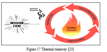
The need to fast-charge the battery, which is important in electric vehicle applications, increases the possibility of thermal runaway and safety issues. There are wide ranging issues affecting the efficiency of energy storage in batteries; particularly, electric vehicle applications strive to improve efficiency in every possible way.
Electric cars have several benefits when replacing ICE cars, including a significant reduction of local air pollution, as they do not emit exhaust pollutants such as volatile organic compounds, hydrocarbons, carbon monoxide, ozone, lead, and various oxides of nitrogen. Like ICE vehicles, electric cars emit particulates from tire and brake wear which may damage health, although regenerative braking in electric cars means less brake dust. [27] More research is needed on non-exhaust particulates. The sourcing of fossil fuels (oil well to gasoline tanks) causes further damage as well as use of resources during the extraction and refinement processes.[29]
D. Project Definition
The Battery Management System in Automobiles serves a vital role of monitoring the different battery parameters and their state. The Estimation of li-ion Battery Parameters using MATLAB Simulink, is a simulation-based system which calculates the different battery pack parameters such as: Current, Voltage, Temperature and State of Charge, under a given set of conditions.
These parameters are calculated within the Simulink system where Battery pack is connected to various blocks to achieve the desired output from the system. This system is responsible for balancing the battery pack passively while charging.
E. Problem Statement
There have been recent reports of multi-million-dollar companies having to recall entire projects due to their BMS’s malfunctioning or operating incorrectly. The purpose of this project is to analyze the future of batteries, the Lithium-Ion cell, and to exercise a BMS to better understand its capabilities and possible cases for errors.
Lithium-ion batteries are intolerant of overcharge and over discharge. Abuse of this kind can result in high temperatures, venting of gasses, fire, or explosion. Therefore, battery management systems have been devised to prevent such abuse. Recent events such as fires on the Boeing Dreamliner and the Tesla Model S have shown that these dangers are real. These products do have highly developed battery management systems, and the incidents were caused despite these systems.
This study was undertaken to illustrate how one system from Texas Instruments functions to monitor and control a simple battery pack. Part I: Battery Data Acquisition Preliminary battery tests were conducted to fully understand the operations of charging and discharging the battery. These tests were essential to gain a better understanding of typical battery behavior and to be able to perform calculations necessary in analyzing the characteristics of the batteries.
Also, these tests were run to ensure that the Lithium-Ion batteries being used correctly corresponded to the graphs and values provided by the datasheet. The knowledge gained from Part I was vital for a better comprehension of the functions needed to balance the cells for Part II as well as the importance of safety precautions necessary when dealing with multiple batteries.
F. Objectives
- Battery State Estimation
This section gives a review of battery state estimation, while focusing on battery key states including SoC, SoH, internal temperature estimation.
2. SoC Estimation
SOC stands for the remaining battery capacity as a percentage to the total in the same situation. 100% stands for the battery fully charged to its total capacity, and 0% stands for battery fully discharged. Accurate SOC estimation plays a vital role in monitoring existing capacity state, to further guarantee the safe and healthy operation of the battery.[2] Two approaches are developed for SOC estimation, which is categorized as direct estimation approach and model-based approach. For the direct estimation approach, based on the direct measurements of battery current and voltage, SOC is mainly calculated by two different ways named Ampere-hour (Ah) or coulomb counting method and open circuit voltage (OCV) based method. Ah method is a general and simple method to calculate SOC.[2]
Since charging or discharging current can be easily measured, Ampere hour (Ah) method becomes a straightforward choice for SOC estimation.[2] However, Ah method is highly dependent on the current measurements, error accumulation over the time will significantly affect the estimation accuracy.[4] Besides, it is difficult to determine the initial SOC accurately in real-time applications especially when the battery is only charged within a limited range, e.g., 10%90%. Calibrations of initial SOC and current become the challenging issues to adopt Ah method for SOC estimation. It has been proposed that there exists a one-to-one nonlinear relation between the battery SOC and OCV.[4] Therefore, using OCV after enough resting to estimate battery SOC has become an effective and popular approach, which has been adopted in many applications.[4]
Although high estimation accuracy of battery SOC can be achieved by the OCV method, the resting time has become a major limitation for OCV-based SOC estimation. It generally takes a long time to reach equilibrium after disconnecting the load current (for example for LiFePO4 battery, duration time is always larger than two hours under low temperature condition). Further, the relation between OCV and SOC also changes along with battery aging and temperature changes. The disadvantages of OCV method limit its wide applications in EVs.[4]
This problem can be addressed if the OCV can be obtained real-time to allow estimation of SOC during driving. Thus, the model-based approach has been developed to calculate OCV to further achieve online estimation of battery SOC.[3] In the model-based approaches, a suitable battery model needs to be carefully designed.[4] Battery equivalent circuit models and electrochemical models in the forms of standard state space are usually selected to estimate battery SOC, while SOC is one of the state variables in these battery models.[4]
Then various state observers are adopted for online SOC estimation, such as Kalman filter (KF), Extended Kalman filter (EKF), Adaptive Kalman filter (AKF), Unscented Kalman filter (UKF), slide mode observer and H1 filter. [7]
The accuracy of these model-based approaches largely depends on the training of the battery models, the adopted state observers, and the parameter tuning such as the key parameters in model and the noise covariance matrix for KF observers.[3] Besides, the performance of battery SOC estimation by these different observers is only validated under limited conditions of the test data, and a reliable confidence-zone is usually difficult to obtain.[3] Therefore, the estimation performance under various practical conditions, which are different from the test conditions, cannot be guaranteed.[7]
3. SoH Estimation
SoH represents battery State of Health. There is no single definition for the battery SoH. A general description of battery SoH can depend on several factors such as current, temperature, SOC, others represent some other stress factors such as the mechanical vibrations and over-potential.[11] For EV applications, battery aging will result in the degradation of battery capacity and the increase of battery internal resistance.[7] Thus, the battery SOH can be estimated by the internal resistance or usable capacity as a kind of prediction regime changes in the computer science field.[14] Numerous approaches have been proposed to estimate battery SOH, which are categorized into three groups, namely, model-free, model-based, and data mining.[3]
One can apply the standard capacity test or pulse current test to measure the battery aged capacity and increased internal resistance. However, this direct method is inconvenient and not recommended because fully discharge using the controlled current and temperature will interrupt the normal EV operations.[13]
Besides, as battery SOH changes at a much slower rate compared with the battery SOC, wider ranges of battery operation and more test data are required to train the battery cycle life model, this inevitably increases the difficulty of engineering implementation.[14]
4. Internal Temperature Estimation
Battery temperature is another key factor to affect the battery performance in many ways such as lifetime, energy conversion efficiency, reliability, and safety. Surface temperature is easy to be measured directly using suitable thermal sensors or thermocouples.[7] But the internal temperature of a battery is an internal state which is difficult to be measured directly. The difference between battery surface and internal temperatures would be quite significant (e.g., sometimes greater than 12 °C in high-power applications).[14] Overheated internal temperature will accelerate battery aging and even lead to safety problems such as fires and explosions.[18]
Therefore, measuring battery surface temperature is insufficient to protect the battery.[7] Proper estimation approaches of internal temperature are capable of not only preventing battery against damages, but also allowing BMS to make reasonable strategies to save energy. One simple method is to inject the proper micro temperature sensors into the battery cell.[14]
However, these methods are often of high cost and complexity due to the accessional manufacturing requirements and instrumentation challenges.[3]
Several improved methods for battery temperature estimation have been proposed, including thermal model-based approaches which usually adopt battery distributed battery thermal model or lumped-parameter battery thermal model.[14] The internal temperature is also selected as one of the state variables in battery thermal models, and various state observers are adopted for on-line internal temperature estimation.[7] By combining the suitable state observers, these model-based approaches can be easily applied to estimate battery internal temperature on-line with good estimation results.[18]
Since the battery thermal models are mainly dependent on the information of heat generating properties and thermal boundary conditions, these model-based approaches also have the challenging issues such as tuning parameters and gaining useful thermal information. Considering that the battery EIS measurements are also related to the variation of battery temperature, therefore battery internal temperature can be also estimated using the EIS measurements.[27]
5. Joint State Estimation
According to the coupled electro-thermal models which are capable of simultaneously describing battery electric and thermal behaviors, the joint state estimation of battery SOC and internal temperature can be achieved, which plays an important role in some control and equalization applications of batteries.[14] The key step to achieve joint state estimation is to build a simple and accurate battery electrothermal model firstly, then suitable estimation methods such as slide mode observer, Kalman filter observer can be applied accordingly.[18]
G. Battery Charging Approach
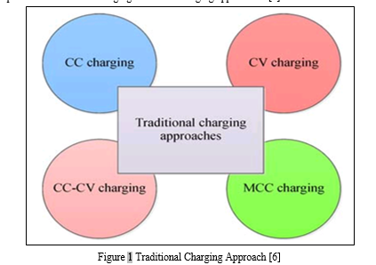
When a battery energy source is exhausted or its terminal voltage drops below the cut-off voltage or SOC declines to 20% or lower, the discharging process must be stopped, and the battery needs to be recharged.[5] The charging performance for various batteries is shown in Table 1. Incorrect operations such as over-discharging, over-charging or improper charging will speed up the degradation process of the battery dramatically.[6] Compared with other types of battery, the Li-ion battery has stable performance but less cycle life at high-temperature conditions, while no permission is allowed for being charged below freezing.[6] According to the accurate estimations of battery SOC, SOH and temperature, proper battery charging approaches can be effectively designed further to charge the battery from initial state to final SOC target value. Meanwhile, the charging approaches can also protect batteries from overheating, prolong the service life and improve the capacity utilization. [6]There are some traditional but popular charging approaches to solve the battery charging problem with numerous objectives and termination conditions. Four traditional charging approaches that have been widely utilized to charge batteries in EVs are listed in Fig. 1.[6] These typical approaches can be mainly classified as constant current (CC) charging, constant-voltage (CV) charging, constant-current-constant-voltage (CC-CV) charging and multi-stage constant-current (MCC) charging. In the following, a particular emphasis is placed on the CCCV charging and MCC charging approaches. [6]
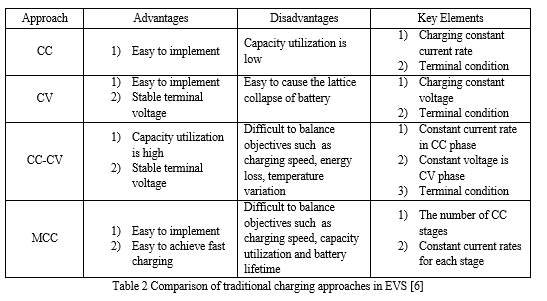
The CC charging is a simple but rough approach which adopts a small constant current rate to charge the battery during the whole charging process.[6]
The CC charging is terminated when the time-to-charge reaches a predefined threshold. This charging approach is first introduced to charge NiCd or NiMH batteries and is also widely used for Li-ion batteries.[5] However, the behaviors of batteries are highly dependent on the current rate in CC charging, hence the main challenge for CC charging approach is to search a suitable charging current rate which is capable of equilibrating battery charging speed and capacity utilization. For large current rates in CC charging, the charging speed is improved but the battery aging process will be aggravated accordingly.[7] For small current rates in CC charging, high-capacity utilization is achieved but too low current rate will slow down the battery charging speed and further have a negative effect on the convenience of EV usage.[6]
Another simple conventional charging approach is the CV charging which totally adopts a predefined constant voltage to charge batteries.[7] The primary superiority of using CV charging is to avoid over-voltage and irreversible side reactions which may occur in the charging process, further, to prolong battery cycle life.[5] When the CV charging is applied, the charging current will gradually reduce due to the low acceptance with progressing recharge. This approach however needs a high current rate to keep constant terminal voltage at the early stage of the charging process, which is easy to cause the battery lattice collapse, and battery poles broken. [6]
|
Battery Type |
Charging Performance |
|
Li-ion |
|
|
Lead Acid |
|
|
NiMH, NiCd |
|
Table 1 Charging performance of various batteries [6]
By integrating CC charging and CV charging, a hybrid charging approach named CC-CV has been proposed. In this approach, a battery is firstly charged by a predefined constant current in CC phase and the battery voltage will increase to the maximum safe threshold.[7] Afterwards, the battery enters the CV phase with a predefined constant voltage, entailing the continuous step-down of the charging current. This CV phase will end until a terminal value of the decreasing current or a goal capacity is reached.[6]
The standard CC-CV approach is first utilized to charge lead acid batteries with the preset values of constant current as well as constant voltage which are recommended by battery manufacturers and is also extended to charge Li-ion batteries with some modifications.[12] Because of higher terminal voltage and charging acceptance for Li-ion battery, constant current in the applications of Li-ion battery CC-CV charging should be much larger than that of lead acid battery, which is usually chosen from 0.5 to 3.0 C.[6]
Another popular traditional charging approach is the MCC charging. This approach has been successfully developed to charge numerous types of battery such as lead acid battery, NiMH battery and Li-ion battery.[8] The main difference between MCC charging and CC-CV charging is that in MCC charging, the multi-stage series of monotonic charging currents are injected into the battery during the total charging process. [6]
This series of charging currents should be gradually reduced as the form of various constant currents stages (ICC1>ICC2>:::>ICCN). When terminal voltage goes up to a default voltage threshold by the constant current in one stage, the charging procedure will turn into another constant current stage and then a new less constant current rate will be utilized accordingly.[7] This decrease process of charging current will continue until battery terminal voltage reaches the last default voltage threshold under the condition of minimum current. The charging speed for standard MCC approach will be usually a bit slower than the standard CC-CV approach with the same initial current. [6]
H. Battery Monitoring and Management
Battery management is mandatory for Li-ion batteries to ensure energy availability, lifetime and safety of the energy storage system. Battery current, voltage and temperature, over time are the major inputs of an electronic battery management system (BMS).[16]
The BMS is in charge of the battery protection and state-of-charge (SoC), state-of-health (SoH) and state-of-function (SoF) estimation.[14] Additional tasks are controlling the heating/cooling subsystem and the main power switch, ensuring the isolation of the high voltage from the vehicle, and implementing isolated communication with the in-vehicle network. From an electronic point of view, challenges are the accurate and synchronous measurement of the battery current and the voltage of the pack cells, along with data communication over a number of voltage domains and fulfillment of ASIL-C safety requirements. [16]
Typical accuracy targets are 0.5 to 1%, for currents up to 450A and 1-2mV and 0.1 % for voltages at cell and pack level respectively. This stringent demand for voltage accuracy is mainly driven by LiFePO4 chemistry.[14] This is one of the preferred technologies for automotive applications, as it features a good compromise among energy density, costs, safety properties, lifetime and cycle resistance.
A very flat characteristic for the open circuit voltage versus state-of-charge stands for this battery technology. This makes accurate state of charge estimation from voltage measurement very difficult, especially in the 20% to 80% state-of-charge range. [16]
Assuming a linear and offset free measurement system, the main error sources in shunt current measurement are the variation of shunt resistance, amplifier gain and ADC reference over temperature and time.[14] The error sources in voltage measurement are ADC reference variation over temperature and time, common mode voltage variation along the battery string and the tolerances affecting the resistive voltage divider. In battery management systems, no re-calibration is foreseen and full accuracy must be maintained for all the vehicle life. However, there are physical reasons for the long term drift of the measurement system.[14]
Most significant ones are related to threshold shift of the metal–oxide–semiconductor (MOS) transistors when biased, mechanical stresses that may induce MOS parameter shift and long-term relaxation effects.[16] Comprehensive qualification tests with the help of highly accurate automatic test equipment resources provide the basis for good accuracy predictions over lifetime. Pre-aging of the electronics in a biased high temperature operating environment needs to be considered to minimize long term accuracy degradation and to achieve the highest accuracy. [16]
I. BMS Topologies
Simple passive regulators achieve balancing across batteries or cells by bypassing charging current when the cell's voltage reaches a certain level.[27] The cell voltage is a poor indicator of the cell's SoC (and for certain lithium chemistries, such as LiFePO4, it is no indicator at all), thus, making cell voltages equal using passive regulators does not balance SoC, which is the goal of a BMS. Therefore, such devices, while certainly beneficial, have severe limitations in their effectiveness.[23]
Active regulators intelligently turning on and off a load when appropriate, again to achieve balancing. If only the cell voltage is used as a parameter to enable the active regulators, the same constraints noted above for passive regulators apply.[19]
A complete BMS also reports the state of the battery to a display and protects the battery.
- BMS Topologies fall in Three Categories
a. Centralized: a single controller is connected to the battery cells through a multitude of wires[23]
b. Distributed: a BMS board is installed at each cell, with just a single communication cable between the battery and a controller[23]
c. Modular: a few controllers, each handling a certain number of cells, with communication between the controllers[23]
Centralized BMSs are most economical, least expandable, and are plagued by a multitude of wires. Distributed BMSs are the most expensive, simplest to install, and offer the cleanest assembly. Modular BMSes offer a compromise of the features and problems of the other two topologies.[27] The requirements for a BMS in mobile applications (such as electric vehicles) and stationary applications (like stand-by UPSes in a server room) are quite different, especially from the space and weight constraint requirements, so the hardware and software implementations must be tailored to the specific use. In the case of electric or hybrid vehicles, the BMS is only a subsystem and cannot work as a stand-alone device. It must communicate with at least a charger (or charging infrastructure), a load, thermal management, and emergency shutdown subsystems. Therefore, in a good vehicle design the BMS is tightly integrated with those subsystems. Some small mobile applications (such as medical equipment carts, motorized wheelchairs, scooters, and forklifts) often have external charging hardware, however the on-board BMS must still have tight design integration with the external charger. [23]
2. Cell Balancing
Cell balancing is one of the main functions of a BMS. A balanced battery is one in which at some state of charge, all the cells are exactly at the same SOC. [6] The cells in a battery may be unbalanced in multiple ways, including SOC, self-discharge current, internal resistance, and capacity. The point of balancing is to maximize the charge that the battery can deliver, limited only by the cell with the lowest capacity. The balancing topologies can be broadly categorized as passive and active balancing. [19]
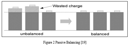
a. Passive Cell Balancing
Passive balancing circuits perform their task by sampling all cell voltages, determining the lowest voltage cell within the stack and leveling all remaining higher voltage cells to this level by removing charge from these higher potential cells.[6] This is illustrated in Figure; where the 3 left most cells are unbalanced and the result of passive balancing is shown on the 3 cells to the right. [19]
This process is easily implemented, low cost and reliable, it is however wasteful and due to its discharge method, it can generate large amounts of unwanted heat that must be dissipated within what is usually a sealed battery pack.[19] Such a method is slow to equalize and requires large areas of PCB real estate to allow for typically surface mount resistor cell load heat dissipation. [19]
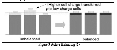
b. Active Cell Balancing
Active cell balancing circuits sample all cell voltages but improve upon the passive technique by calculating the mean value of the cells then transferring the charge from the cells over this mean value to the cells under the mean value.[19] Simply put this equalizes higher potential cells with that of the lower potential cells resulting in no waste, the only actual losses in such a system are from those within the active balancing electronics itself. [19]
Active balancing can be subdivided into further topologies such as capacitor and/or inductive components as well as controlling switches or converters. [19]
c. Performance Optimization
BMS is responsible for optimizing the performance of the battery pack. Lithium-ion batteries perform best when their State of Charge (SoC) is maintained between the minimum and maximum charge limits defined in the battery profile.[14] Overcharging as well as deep discharging degrades the capacity of the battery, thereby shortening its life. At the time of charging, BMS determines how much current can safely go in and communicates the same to the EVSE (Electric Vehicle Supply Equipment or the Charger).[6] During discharge of the battery, BMS would communicate with the motor controller to avoid the cell voltages reaching too low. The vehicles can show a corresponding alert to the user to charge the battery pack. [19]
The BMS also controls the recharging of the battery pack by energy generated through regenerative braking. Individual cells in the battery pack can develop differences in capacity with time, which amplify with each charge/discharge cycle.[14] This imbalance limits the amount of energy that can be derived from the battery, and how much the battery pack can be charged. Cell Balancing is needed to maintain the cells at equal voltage levels and maximize the capacity utilization of the battery pack. [19]
Measurement of individual cell voltages by BMS indicates their relative balance and acts as a pointer to how much charge equalization is required.[6] The BMS performs cell balancing by draining excess energy from cells that are more charged than others, through active or passive balancing techniques. [19]
- Evaluation of Lithium-Ion Battery Equivalent Circuit Models for State of Charge Estimation by an Experimental Approach (Hongwen He , Rui Xiong and Jinxin Fan) [2]
The Paper is based on an analysis of the traditional lithium-ion battery equivalent circuit models such as the Rint, RC, Thevenin and PNGV models, an improved Thevenin model, named dual polarization (DP) model, is put forward by adding an extra RC to simulate the electrochemical polarization and concentration polarization separately. It can be found that the proposed DP model has the best dynamic performance and gives a more accurate SoC estimation. It is observed that with REKF approach the error resulting from the SoC initial values is significantly reduced and the true SoC is convergent within an acceptable error.
2. A Review on Battery Management System for Electric Vehicles (Omkar S Chitnis, Dr. M. S. Sheshgiri) [7]
The battery management system (BMS) is a critical component of electric and hybrid electric vehicles. The purpose of the BMS is to guarantee safe and reliable battery operation. To maintain the safety and reliability of the battery, state monitoring and evaluation, charge control, and cell balancing are functionalities that have been implemented in BMS.
3. A review on the key issues for lithium-ion battery management in electric vehicles (Languang Lua, Xuebing Hana, Jianqiu Lia, Jianfeng Huab, Minggao Ouyang.) [8]
This present paper, through the analysis of literature and in combination with our practical experience, gives a brief introduction to the composition of the battery management system (BMS) and its key issues such as battery cell voltage measurement, battery states estimation, battery uniformity and equalization, battery fault diagnosis and so on, in the hope of providing some inspirations to the design and research of the battery management system.
4. Battery-Management System (BMS) and SOC Development for Electrical Vehicles (K.W.E. Cheng, Senior Member, IEEE, B. P. Divakar, Hongjie Wu, Kai Ding, and Ho Fai Ho) [28]
In this paper, a typical BMS block diagram has been proposed using various functional blocks. The state of charge (SOC) estimation has been implemented using Coulomb counting and open-circuit voltage methods, thereby eliminating the limitation of the stand-alone Coulomb counting method.
By modeling the battery with SOC as one of the state variables, SOC can be estimated, which is further corrected by the Kalman filtering method. The battery parameters from experimental results are integrated in the model, and simulation results are validated by experiment.
5. Battery Management System (BMS) Simulation Environment for Electric Vehicles (Luca Buccolini, Adrianna Ricci, Cristiano Scavongelli, Giuseppe DeMaso-Gentile, Simone Orcioni) [5]
The main objective of this work is to develop a simulation environment based on System C to design and optimize the Battery Management System including a lithium-ion battery model and CAN communication interface. The BMS has been validated using real-world scenarios and data.
6. State-of-Health Estimation of Li-ion Batteries: Cycle Life Test Methods (JENS GROOT) [14]
Despite a rapid development, cost, performance, and durability of the energy storage system is still a hindrance for a wide commercialization of heavy-duty hybrid electric vehicles (HEV). The purpose of the work presented in this thesis is to investigate how different load cycle properties affect the cycle life and ageing processes of Li-ion cells developed for use in HEVs.
7. An overview of lithium-ion batteries for electric vehicles (Xiaopeng Chen; Weixiang Shen; Thanh Tu Vo; Zhenwei Cao; Ajay Kapoor) [27]
This paper reviews four types of commonly used lithium-ion batteries and based on their specifications analysis to access capabilities and suitability as the energy source in EVs. Results can be used as benchmarks for selecting lithium-ion batteries for battery management system (BMS) design in EVs.
8. Design and Implementation of an Optimal Battery Management System for Hybrid Electric Vehicles (Mark Bowkett, Kary Thanapalan, Thomas Stockley, Mark Hathway, Jonathan Williams) [19]
This paper presents an overview of different cell balancing topologies and their impact on system performance. Furthermore, the application of cell balancing topologies for Lithium-ion battery pack with the view of improving battery management systems for the hybrid electric vehicles is also investigated.
Real-time implementation of an optimal battery management system is discussed with references to the University of South Wales (USW) hybrid electric vehicles.
9. Combined State of Charge and State of Health estimation over lithium-ion battery cell cycle lifespan for electric vehicles (Yuan Zou, Xiaosong Hu, Hongmin Ma Shengbo Eben Li) [13]
A combined SOC (State of Charge) and SOH (State of Health) estimation method over the lifespan of a lithium-ion battery is proposed. First, the SOC dependency of the nominal parameters of a first-order RC (resistor-capacitor) model is determined, and the performance degradation of the nominal model over the battery lifetime is quantified. Second, two Extended Kalman Filters with different time scales are used for combined SOC/SOH monitoring: the SOC is estimated in real-time, and the SOH (the capacity and internal ohmic resistance) is updated offline.
10. A comprehensive model for lithium-ion batteries: from the physical principles to an electrical model (Alberto Berrueta, Andoni Urtasun, Alfredo Ursúa, Pablo Sanchis) [15]
This model has the required simplicity to be used in the simulation of a whole battery, while providing the depth of detail needed to identify physical phenomena. Moreover, due to its high accuracy, it can be used in a wide range of environments, as shown in the experimental validations carried out in the final section of this paper.
11. A Review of Cathode and Anode Materials for Lithium-Ion Batteries (Yemeserach Mekonnen , Aditya Sundararajan and Arif I. Sarwat) [20]
This paper presents a comprehensive review of the existing and potential developments in the materials used for the making of the best cathodes, anodes, and electrolytes for the Li-ion batteries such that maximum efficiency can be tapped. Observed challenges in selecting the right set of materials is also described in detail. This paper also provides a brief history of battery technology and their wide applicability in the energy market today, the chemistry and principle of operation behind the batteries, and their potential applications even beyond the energy sector. Safety concerns related to Li-ion batteries have also been considered considering recent events.
12. Investigating the error sources of the online state of charge estimation methods for lithium-ion batteries in electric vehicles (Yuejiu Zhenga, Minggao Ouyangb, Xuebing Hanb, Languang Lub, Jianqiu Li) [1]
A book perspective focusing on the error analysis of the SOC estimation methods is proposed. SOC estimation methods are analyzed from the views of the measured values, models, algorithms, and state parameters. Subsequently, the error flow charts are proposed to analyze the error sources from the signal measurement to the models and algorithms for the widely used online SOC estimation methods in new energy vehicles.
A. History of BMS
Battery technology has been used since the invention of the first voltaic cell in the 1800s and a lot of research has been performed for batteries and applications. Because of the increased interest in hybrid vehicles and battery EVs, a BMS has become one of the chief components in these vehicles. The main goal of BMS is to minimize the variation between the cells in the battery pack.[1] Therefore, the run-time per cycle can be increased, and in addition, a higher number of cycles can be achieved.[2] The Battery management system (BMS) has been progressing speedily for the last decades due to the rapid growth of renewable energy-based power generation, development of smart grid technology, expansion of electric vehicle (EV) production and reduction of CO2 emission. EVs are the growing technologies with the progress of BMS to substitute fossil fuels and mitigate carbon emissions. Nevertheless, EV is facing challenges due to the short lifespan and slow charging process of BMS. [23]
Today’s BMS technology is inadequate to accurately predict the state of health (SOH) of a battery. The available choices are either to prematurely replace the battery or to wait until an explicit failure event occurs.[4] Both choices have undesirable consequences: premature replacement will result in increased cost to the end user and excessive waste to the environment; waiting out will negatively impact the safety and quality of experience to the end user. [23]
Among eco-friendly energy sources, lithium-ion batteries have been widely used in the energy industry as a replacement for lead-acid batteries and Ni-MH batteries since they offer the advantages of high energy and power densities, long life expectancy, and low self-discharge rate[2]. Thus, lithium-ion batteries have been adopted in many energy storage systems (ESSs) [3]. However, lithium-ion batteries have an economic disadvantage owing to their need for expensive raw materials such as cobalt, etc. [23]
Electricity was among the preferred methods for automobile propulsion in the late-19th and early-20th centuries, providing a level of comfort and an ease of operation that could not be achieved by the gasoline-driven cars of the time. The electric vehicle fleet peaked at approximately 30,000 vehicles at the turn of the 20th century.[23]
Despite rapid growth, about 1 out of every 100 cars on the world's roads were fully electric and plug-in hybrid cars by the end of 2020. China has the largest all-electric car fleet in use, with 2.58 million at the end of 2019, more than half (53.9%) of the world’s electric car stock.[23]
An electric vehicle charging network is an infrastructure system of charging stations to recharge the battery in electric vehicles. Many government, car manufacturers, and charging infrastructure providers sought to create networks.[23] As of now the largest fast-charging location was in California on the Tesla Supercharger network, with 56 charging stalls.[10] Today, charging network vendors include either proprietary solutions (ex. Tesla or Charge point), or hardware agnostic solutions (ex. Amp Up, EV Connect, and green lots). Hardware-agnostic vendors allow for customers to switch out their charge stations and/or switch to a different network vendor ; whereas proprietary vendors do not allow for customers to switch. [23]
B. Comparative Study of Different Types of BMS
Batteries are generally grouped into two categories based on the ability of recharging: Primary and secondary battery. The primary battery can be just used once after being fully discharged, and the secondary battery is capable of being recharged after the discharging process.[6] For the applications of EVs and HEVs, the secondary battery with long cycle life, small energy loss, high power density and enough safety level is indispensably required.[23]
Some popular types of batteries used in EVs include lithium-ion (Li-ion), lead acid, nickel-cadmium (NiCd) and nickel-metal hydride (NiMH), etc. It is clearly known that Li-ion battery is significantly better than other Popular types of battery in EVs, especially in terms of large cycle life which is key to long service of EVs (e.g., 6–10 years’ service life).[8] Besides, Li-ion battery is also composed of eco-friendly materials without toxic gassing problems and has a high safety level. Therefore, Li-ion battery has become the most popular power supply for EVs. [7] There are two different categories of battery cells namely Primary cells and Secondary cells. In case of primary cells, the electrochemical reaction that occurs during the discharge is not reversible.[7] If we try to recharge a primary battery, the compounds that have been formed during discharge will not recombine into the original compounds that were present before discharge and therefore it’s not rechargeable.[8]
This is the principal reason that primary cells are meant for only one time use. Secondary cells are special in the sense that their chemical reaction has been designed in such a way that it is completely reversible.[7] The original chemical compounds that are changed during discharge can be reconstituted into its original form by the application of external potential between the electrodes that inject energy into the cell. Secondary cells can be discharged and recharged infinite times but their life is limited by degradation of the cells. [8]
C. BMS Related Research Work
Prognostics and health management (PHM) is an enabling strategy consisting of technologies and methodologies for BMS. By monitoring the sensor signals and processing real time data from a BMS, the battery status, including SOC and SOH, can be estimated and predicted to provide end users with an accurate “gauge meter” in an EV. Based on the data collected, the BMS determines the corresponding maintenance strategies. Meanwhile, abnormality detection can be used to capture signals to update the predictive results and guarantee the safety and reliability of batteries. [6]
Our view is to measure and collect current, voltage, and temperature as the main operational parameters in order to improve feasibility and reduce design costs.[2] Many kinds of lithium-ion batteries are employed in electric vehicles (EV).The most widely used power battery cells contain carbon anode(negative electrodes, and now the LTO anode is also developed fast for these kinds of anodes would help to improve the battery durability and performance of fast charging.[6] The positive electrode material of the power battery could be Lithium Manganese Oxide (LMO), Lithium Iron Phosphate (LFP), Nickel Cobalt Manganese (NCM), Nickel Cobalt Aluminum (NCA), etc. Some of the current EV and the employed batteries are listed in.[7] Usually, the capacity and voltage of the battery cell used in the EV are relatively small. So first the single battery cells should be packed and integrated to a battery module, and the battery system in the EV often contains one or more modules according to the requirement.[6] The battery system usually consists of hundreds or thousands of single cells.[8]
To manage so many cells, the battery management system (BMS) is very important. There is still no consensus on the final definition of BMS and what BMS do.[6] We adopt the wide view that BMS is any system that manages the battery. The system could be electronic systems, mechanical systems or any possible device and technology. The battery could be a single cell, battery module or battery pack, and it could be rechargeable or non-rechargeable.[8]
D. Importance of BMS
Battery temperature is another key factor to affect the battery performance in many ways such as lifetime, energy conversion efficiency, reliability, and safety. Surface temperature is easy to be measured directly using suitable thermal sensors or thermocouples.[8] But the internal temperature of the battery is an internal state which is difficult to measure directly. The difference between battery surface and internal temperatures would be quite significant (e.g., sometimes greater than 12°C in high-power applications).[7] Overheated internal temperature will accelerate battery aging and even lead to safety problems such as fires and explosions.[8] Therefore, measuring battery surface temperature is insufficient to protect the battery. Proper estimation approaches of internal temperature are capable of not only preventing battery against damages, but also allowing BMS to make reasonable strategies to save energy. [6]
E. Benefits of Electric Vehicle
Electric vehicles are around 3-5 times more efficient than internal combustion vehicles in utilizing energy. Even if electric vehicles run on electricity produced from fossil fuels, the overall efficiency of electric vehicles is still higher and the pollution is less, because large thermal power plants are much more efficient than IC engines, and it is easier to control emissions from power plants than vehicle engines.[23]
Electric vehicles save energy by regenerative braking. Around 30%-70% of the energy used for propulsion can be recovered, with higher percentages applicable to stop-and-go city driving. If electric vehicles run on electricity produced from non-polluting sources of energy like hydro, solar, wind, tidal and nuclear, they reduce emissions due to vehicles almost to zero.[11]
Electric vehicles are much quieter and may contribute to a reduction in noise pollution levels in the cities.[23] Through smart charging, electric vehicles can help to balance the balance-supply variations in the electricity grid and provide a buffer against electricity supply failures.[11] Electric vehicles have much fewer moving parts as compared to vehicles with IC engines. Thus, being simpler, they are cheaper and easier to maintain.[11] Electric motors can deliver high torque at low speeds. As a result, electric vehicles deliver much better performance while starting off and on slopes than IC engine-powered vehicles. [23]
III. BATTERY MODELING
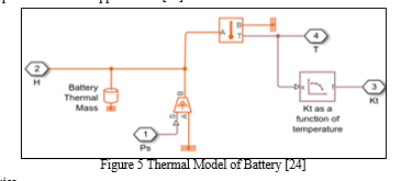
A battery model is necessary in this study for two reasons. First, the estimation algorithms require a map relating the electrochemical variables that are unavailable from measurements to the signals that are measurable in practice.[2] In this work, this map is a battery model that relates the side reaction current density/the number of cyclable Li-ions to the battery terminal voltage and current. Second, a battery model is required to represent a battery in simulations.[24]
Battery system consists of battery cells. Depending on the requirement of output voltage, power and energy capacity for an EV, a battery pack contains many cells connected in series or parallel or both.[24] Battery operation and its input-output parameters can be studied by modeling the battery. Proper model of the battery is required for a good BMS design, control, and optimization. There are several methods available to model a battery, and the most widely used are electric model, thermal model, and electro-thermal model.[24]
Building a proper model is usually the starting point for BMS design, control, and optimization. Over the years, numerous battery models with various levels of accuracy and complexity have been developed. These models can be primarily categorized as the battery electric model, battery thermal model, and battery coupled model.
Battery system consists of battery cells. Depending on the requirement of output voltage, power and energy capacity for an EV, a battery pack contains many cells connected in series or parallel or both.
Battery operation and its input-output parameters can be studied by modeling the battery. Proper model of the battery is required for a good BMS design, control, and optimization. There are several methods available to model a battery, and the most widely used are electric model, thermal model, and electro-thermal model. [24]
A. Battery Electric Model
Battery electric models mainly include electrochemical model, reduced-order model, equivalent circuit model and data-driven model. For the electrochemical model, Rahman et al claimed that the battery electrochemical model should have the abilities to capture the spatiotemporal dynamics of battery concentration, the electrode potential for each phase and the Butler Volmer kinetic to control intercalation reaction.[24] Then an electrochemical model is established to describe battery electrochemical behaviors by using particle swarm optimization (PSO) method to optimize critical model parameters. Sung and Shin showed that the electrochemical model presented a highly accurate prediction performance but required significant computation effort in model simulation.[24] 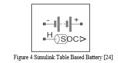
Then a model implementation scheme was developed to embed an electrochemical model into the BMS. The main advantage of using an electrochemical model is that a highly accurate description of electrochemical processes within the battery can be obtained. However, many parameters relating to the battery electrochemistry such as chemical compositions need to be identified, which is practically difficult to achieve in real-time applications.
Besides, these electrochemical models usually involve many partial differential equations which need to be solved, resulting in large computational overheads. By making suitable assumptions, the full-order electrochemical models can be approximated by reduced-order models. For example, Han et al proposed an approximate method to capture the solid phase diffusion and electrolyte concentration distribution of batteries, then a simplified physics-based electrochemical model was developed to estimate Li-ion battery SOC. Zou et al proposed a reduced-order electrochemical model for LiFePO4 battery to predict discharging capacity under various conditions, then robust SOC estimation was achieved based on this reduced-order battery model.[6]
Although this approach leads to some information loss in the simplified reduced-order models, they are more desirable for real-time applications of batteries. The computational overheads become much lower for reduced-order models, and the corresponding parameters can be identified by the measured current and voltage signals. For equivalent circuit models, battery electric behaviors have been captured by a combination of circuit components, such as resistances, capacities, voltage sources. [11]
B. Battery Thermal Model
Thermal behavior such as temperature is also a key aspect in the BMS of EVs because temperature plays a vital role in battery performance and lifetime. Various models such as heat generation model, heat transfer model, reduced-order thermal model and data-driven model have been developed to capture the thermal behaviors of batteries. For the heat generation model, several methods are introduced to describe the heat generation in the battery, such as activation, concentration and ohmic losses, which distribute non-uniform inside the battery. Three popular approaches to assess the heat generation in the batteries are illustrated which have been widely applied in real-time applications. [24]
C. Types of Li-ion Batteries
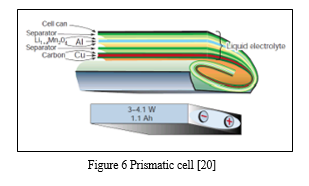
Lithium-ion batteries are available in various forms. Coin battery, cylindrical battery, Pouch battery and Prismatic battery. The cylindrical and prismatic batteries are built from wound electrodes and separators, immersed in electrolyte, containing several electrochemical cells within. The coin battery is a small flat construction containing a single electrochemical cell within it, while the pouch battery is also a flat construction, but containing several electrochemical cells within. [20] Cylindrical, prismatic, and pouch packaging are often used in automotive applications because of the larger surface areas of the positive and negative electrodes. [20] The intended operating conditions for the battery determine which packaging is selected by the automotive manufacturer. For example, the Chevrolet Volt and Nissan Leaf use pouch batteries while the Tesla Model S uses cylindrical batteries. Usually, cylindrical cells designs are limited to below 4 Ah while prismatic cells designs are used for higher capacity ratings. [1]
- Prismatic Cell Battery Packs
Prismatic cells are also making critical inroads into larger formats. Packaged in welded aluminum housings, the cells deliver capacities of 20 to 30Ah and are primarily used for electric powertrains in hybrid and electric vehicles. Figure 4shows the prismatic cell. [20] The prismatic cell requires a slightly thicker wall size to compensate for the decreased mechanical stability from the cylindrical design, resulting in a small capacity drop. Optimizing use of space makes up this loss. Prismatic cells for portable devices range from 400 mAh to 2,000 mAh. [20] Prismatic cells are contained in a rectangular can. The electrodes are either stacked or in the form of a flattened spiral. They are usually designed to have a very thin profile for use in small electronic devices such as mobile phones. Prismatic cells provide better space utilization at the expense of slightly higher manufacturing costs, lower energy density and more vulnerability to swelling, but these are minor effects which don't constitute a major disadvantage. [20] The prismatic cell improves space utilization and allows flexible design but it can be more expensive to manufacture, less efficient in thermal management and have a shorter cycle life than the cylindrical design. [20]
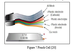
2. Pouch Cell
In 1995, the pouch cell surprised the battery world with a radical new design. Rather than using a metallic cylinder and glass-to-metal electrical feed-through for insulation, conductive foil tabs welded to the electrode and sealed to the pouch carry the positive and negative terminals to the outside. [20]
The pouch cell makes the most efficient use of space and achieves a 90 to 95 percent packaging efficiency, the highest among battery packs. Eliminating the metal enclosure reduces weight but the cell needs some alternative support in the battery compartment. [20]
The pouch cell offers a simple, flexible, and lightweight solution to battery design. Exposure to high humidity and hot temperature can shorten service life. [20]
The pouch battery pack can be found in applications in consumer, military, as well as automotive industries. No standardized pouch cells exist, so each manufacturer builds the cells for a specific application. Pouch packs are commonly Li-polymer. Its specific energy is often lower and the cell is less durable than Li-ion in the cylindrical package. [20]
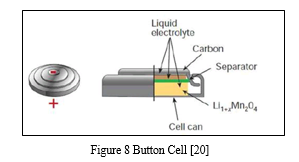
3. Button Cell
A button cell, watch battery, or coin battery is a small single-cell battery shaped as a squat cylinder typically 5 to 25 mm (0.197 to 0.984 in) in diameter and 1 to 6 mm (0.039 to 0.236 in) high resembling a button. Stainless steel usually forms the bottom body and positive terminal of the cell; insulated from it, the metallic top cap forms the negative terminal. [20]
Button cell use in RTC modules as power source. Button cells are used to power small portable electronics devices such as wrist watches and pocket calculators. Wider variants are usually called coin cells. [20]
Most button cells have low self-discharge, holding their charge for a long time if not used. Relatively high-power devices such as hearing aids may use a zinc–air battery, which has a much higher capacity for a given size but dries out after a few weeks even if not used. [20]
Button cells are single cells, usually disposable primary cells. Common anode materials are zinc or lithium. Common cathode materials are manganese dioxide, silver oxide, carbon monofluoride, cupric oxide or oxygen from the air. Mercuric oxide button cells were formerly common but are no longer available due to the toxicity and environmental effects of mercury.
Button cells are dangerous for small children, as when swallowed they can cause severe internal burns and significant injury or death. [20]
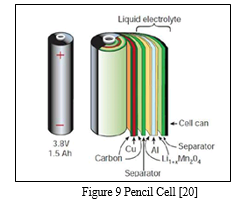
4. Pencil Cell
Pencil cells also called as dry cells commonly used batteries containing metal electrode or graphite rod covering moist electrolyte paste in a cylindrical shaped metal. Whereas cathode along with the electrolytic coating is sealed into a metal cylinder called anode and made up of zinc. There are two different categories of battery cells namely Primary cells and Secondary cells. In case of primary cells, the electrochemical reaction that occurs during the discharge is not reversible. [20]
If we try to recharge a primary battery, the compounds that have been formed during discharge will not recombine into the original compounds that were present before discharge and therefore it’s not rechargeable. [20]
This is the principal reason that primary cells are meant for only one time use. Secondary cells are special in the sense that their chemical reaction has been designed in such a way that it is completely reversible. [20]
The original chemical compounds that are changed during discharge can be reconstituted into its original form by the application of external potential between the electrodes that inject energy into the cell. Secondary cells can be discharged and recharged infinite times but its life is limited by degradation of the cells. [20]
Some popular types of batteries are Dry cell, Alkaline cell, lithium-ion (Li-ion), lead-acid (PbA), Nickel-Cadmium (NiCd), Nickel-Metal Hydride (NiMH), Nickel Zinc, Zinc air, as shown in Table with their electrochemistry.[28]
|
Electrochemistry |
Nominal Voltage |
Negative Electrode |
Positive Electrode |
Electrolyte |
|
Lead-Acid |
2.1V |
Pb |
PbO2 |
H2SO4 |
|
Dry Cell |
1.6V |
Zn |
MnO2 |
ZnCl2 |
|
Alkaline |
1.5V |
Zn |
MnO2 |
KoH |
|
Nickel Cadmium |
1.35V |
Cd |
NiooH |
KoH |
|
Nickel Zinc |
1.73V |
Zn |
NiooH |
KoH |
|
Zinc Air |
1.65V |
Zn |
O2 |
KoH |
|
Nickel Metal Hydride |
1.2V |
H2 in the form of metal hydride |
Ni(OH)2 |
KoH |
|
Lithium ion |
3.7V |
Graphite |
LFP, LMO, LCO |
LiPF6 |
Table 3 Different types of batteries and their electrochemistry [28]
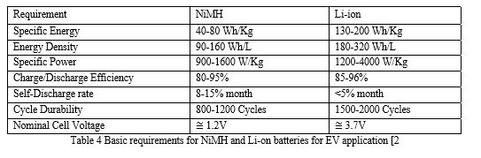
Among the above different types of batteries, NiMH and Li-ion batteries are highly preferred. NiMH has higher specific energy, energy density than cadmium electrodes. They have higher capacity and longer life than NiCd batteries. Since it is free of cadmium they are considered as an environment friendly battery. The magic of NiMH cells is the negative electrode which is a rare earth hydrogen absorbing metal alloy. [15]
There is no electrochemical reaction taking place in the negative electrode that changes its structure when hydrogen goes in and comes out of the electrode.[15] The Li-ion cells also allow intercalation of lithium ions into crystalline lattice of graphite without changing its crystalline structure. Li-ion batteries have higher open circuit voltage which reduces the number of cells in a battery pack.
Higher energy density makes the battery pack compact and high specific energy lightens the overall weight of the vehicle. They can be operated in a wide temperature range without decreasing its lifetime. Li-ion batteries can be charged and discharged at higher C-rate at normal operating conditions, so that a small battery pack can meet peak power requirements and absorb most regenerative energy. [15]
D. Battery Selection Criteria
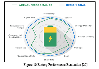
The one thing to remember about battery selection is that there is no such thing as a perfect battery that works for every application. Selecting the right battery for your application is about identifying the most important battery metrics and trading these off against others. For instance, if you need a lot of power for your application, cell internal resistance needs to be minimized, and this is often done by increasing electrode surface area. But this also increases inactive components such as current collectors and conductive aid, so energy density is traded off to gain power. [22]
While your actual design goals on the battery may be lofty, you could have to give up some things to gain others when it comes to actual battery performance. [22]
A lead acid battery works great in an automotive starter battery where it provides the required high-rate capability. However, with its toxicity and low energy density it would be a terrible choice for a portable electronics application. [22]
- Primary vs. Secondary: One of the first choices in battery selection is to decide whether the application requires primary (single use) or secondary (rechargeable) batteries. For the most part, this is an easy decision for the designer. Applications with occasional intermittent use (such as a smoke alarm, a toy, or a flashlight), and disposable applications in which charging becomes impractical warrant the use of a primary battery. Hearing aids, watches (smartwatches being an exception), greeting cards and pacemakers are good examples. If the battery is to be used continuously and for long stretches of time, such as in a laptop, a cell phone, or a smartwatch a rechargeable battery is more suitable. [22]
2. Energy vs. Power: The runtime of a battery is dictated by the battery capacity expressed in mAh or Ah and is the discharge current that a battery can provide over time. [22]
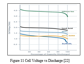
3. Voltage: Battery operating voltage is another important consideration and is dictated by the electrode materials used. A useful battery classification here is to consider aqueous or water based batteries versus lithium based chemistries. Lead acid, Zinc carbon and Nickel metal hydride all use water based electrolytes and have nominal voltages ranging from 1.2 to 2 V. Lithium based batteries, on the other hand, use organic electrolytes and have nominal voltages of 3.7 to 4.2 V (both primary and secondary). [22]
4. Temperature Range: Battery chemistry dictates the temperature range of the application. For instance, aqueous electrolyte based Zinc-carbon cells cannot be used below 0°C. Alkaline cells also exhibit a sharp decline in capacity at these temperatures, although less than Zinc-carbon. Lithium primary batteries with an organic electrolyte can be operated up to -40°C but with a significant drop in performance.[22]
5. Shelf Life: This refers to how long a battery will sit in a storeroom or on a shelf before it is used. Primary batteries have much longer shelf lives than secondary. However, shelf life is generally more important for primary batteries because secondary batteries can be recharged. An exception is when recharging is not practical.[22]
6. Chemistry: Many of the properties listed above are dictated by cell chemistry. We will discuss commonly available battery chemistries in the next part of this blog series.[22]
7. Physical Size and Shape: Batteries are typically available in the following size formats: button/coin cells, cylindrical cells, prismatic cells, and pouch cells (most of them in standardized formats).[22]
8. Cost: There are times when you may need to pass up a battery with better performance characteristics because the application is very cost sensitive. This is especially true for high volume disposable applications. [22]
9. Transportation, Disposal Regulations: Transportation of lithium-based batteries is regulated. Disposal of certain battery chemistries is also regulated. This may be a consideration for high volume applications. [22]
E. Lithium-ion Battery Formation
Li-ion batteries can be constructed and packed in two major formations, which are metal cans either in cylindrical or prismatic shapes or laminate films (stacked cells) that are familiarized as Li-ion polymer batteries. Li-ion batteries can be shaped as the cylindrical structure of rolled and plastered layers in metal cans with electrolytes. In the stacked form, the three layers are confined in laminate film and where their edges are heat-sealed aluminized plastic. A gel or polymer is often used to prevent the electrolyte from leaking in this package. For the energy source in EVs, Li-ion cells must be assembled into modules and then further composed into battery packs of series- parallel connected cells to achieve the precise energy demands. Prismatic Cell Battery Packs, introduced in the early 1990s, the prismatic cell satisfies the demand for thinner sizes and lower manufacturing costs. Wrapped in elegant packages resembling a box of chewing gum or a small chocolate bar, prismatic cells make optimal use of space by using the layered approach.[1] These cells are predominantly found in mobile phones with lithium-ion. No universal format exists and each manufacturer designs its own. If the housing design allows a few millimeters extra in a cell phone or laptop, the manufacturer designs a new pack for the sake of higher capacity. High volume justifies this move.
1. Series Formation
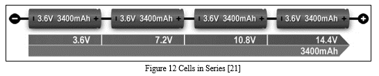
Portable equipment needing higher voltages use battery packs with two or more cells connected in series. Figure shows a battery pack with four 3.6V Li-ion cells in series, also known as 4S, to produce 14.4V nominal. In comparison, a six-cell lead acid string with 2V/cell will generate 12V, and four alkaline with 1.5V/cell will give 6V. [21]
If you need an odd voltage of, say, 9.50 volts, connect five lead acids, eight NiMH or NiCd, or three Li-ion in series. The end battery voltage does not need to be exact if it is higher than what the device specifies. A 12V supply might work in lieu of 9.50V. Most battery-operated devices can tolerate some over-voltage; the end-of-discharge voltage must be respected, however. [21]
2. Parallel Formation
If higher currents are needed and larger cells are not available or do not fit the design constraint, one or more cells can be connected in parallel. Most battery chemistries allow parallel configurations with little side effect. Figure 4 illustrates four cells connected in parallel in a P4 arrangement.[21]
The nominal voltage of the illustrated pack remains at 3.60V, but the capacity (Ah) and runtime are increased fourfold.[21]
A cell that develops high resistance or opens is less critical in a parallel circuit than in a series configuration, but a failing cell will reduce the total load capability. It’s like an engine only firing on three cylinders instead of on all four.[21] An electrical short, on the other hand, is more serious as the faulty cell drains energy from the other cells, causing a fire hazard. Most so-called electrical shorts are mild and manifest themselves as elevated self-discharge. [21] 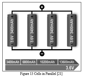
F. Types of Fault in the Li-Ion Battery System
- Interal Battery Faults
Internal battery faults are difficult to detect since the operation within a Li-ion cell is still not fully understood. Some examples of internal battery faults are overcharge, over-discharge, internal and external short circuit, overheating, accelerated degradation, and thermal runaway.[26] All these faults affect the battery operation, but accelerated degradation and thermal runaway are the most dangerous since they can significantly affect the Li-ion battery application or directly harm the users. Internal faults are often identified from abnormal responses from the battery operation, which include voltage drop, SOC drop, temperature rise, increase in internal resistance, and physical transformation, such as swelling. [26]

2. Overcharge
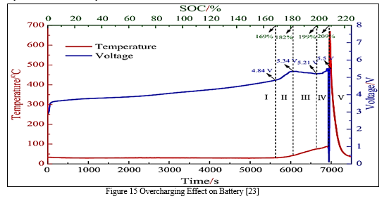
Overcharge is a fault that can lead to more severe faults, such as accelerated degradation and thermal runaway. It may occur in Li-ion cells due to the capacity variation of cells in the pack, incorrect voltage and current measurement, or inaccurate SOC estimation from the BMS.[23] Anormal battery pack can also get overcharged when the charger breaks down. Overcharging of Li-ion batteries leads to electrochemical reactions between battery components and the loss of active materials. [23]
Additionally, in sealed batteries, the buildup of gasses could cause the battery to burst. Furthermore, the surface temperature of the battery increases significantly before it starts overcharging.[23] This results in a thick SEI layer and causes an internal short circuit inside the battery. The overcharged cathode suffers from electrolyte decomposition, metal dissolution, and phase transition, which could ultimately lead to thermal runaway and fires.[23]
3. Overheating
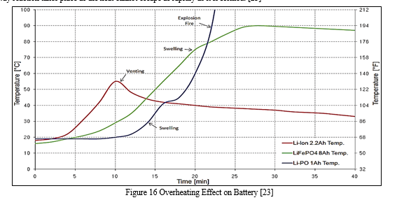
A Li-ion battery can overheat if an alternator’s voltage regulator fails, sending a high amount of voltage back to the battery and causing overheating. [25] Overheating can also be caused by external and internal short circuits. Overheating of the battery accelerates the degradation of the cathode and leads to SEI growth at the anode. [23]
As a result of overheating, there is a significant capacity loss. [23] Overheating of Li-ion batteries can lead to the materials inside the battery to break down and produce bubbles of gas, and, in most cases, the pressure build-up causes the battery to swell and possibly explode. [26] Another consequence of overheating is thermal runaway, which occurs because, at a critical temperature, a runaway reaction takes place as the heat cannot escape as rapidly as it is formed. [23]
4. Thermal Runaway
All the above internal battery faults can cause thermal runaway. It can also occur during the charging of the battery under extreme charging currents and high temperatures. [12] When the temperature reaches the melting point of the metallic lithium, it can cause a violent reaction. Restricted air circulation is another cause of thermal runaway. The probability of thermal runaway increases with the number of charge/discharge cycles. [12]
It is also found that thermal runaway is related to a variety of exothermic reactions in batteries. [12] The first exothermic reaction to occur is SEI decomposition, and it considerably increases the heat release at the beginning of thermal runaway.[24] During thermal runaway, the cathode releases oxygen by a phase transition, and the oxygen is consumed by the lithiated anode. [12]
A consequence of thermal runaway is a substantial increase in pressure and temperature of the Li-ion cell, which can lead to the destruction of the container and the release of a large amount of flammable and toxic gas. [12] Often in the case of a thermal runaway occurrence, the battery heats up and explodes. Hence, it is the most severe fault that can materialize in a Li-ion battery system. [12]
G. External Battery Faults
External battery faults can have a significant effect on the other functions of the BMS and cause internal battery faults to occur. There are several types of external faults, which are temperature, voltage and current sensor faults, cell connection fault, and cooling system fault.
The cooling system fault can be considered the most severe fault because it leads to a direct thermal failure, specifically thermal runaway, as the system fails to provide adequate cooling. [8] [26]
- Sensor Fault: Sensor faults include failure of temperature, voltage, and current sensors. Sensor faults are caused by vibration, collision electrolyte leakage, and other physical factors. They can also be attributed to the loose battery terminals or corrosion around the battery sensor.[21] A sensor fault can accelerate the degradation process of a battery, hinder the BMS functions due to incorrect state estimation, and cause other internal battery faults.[26] A temperature sensor fault can cause it to send incorrect measurements to the BMS, which can cause further problems due to ineffective thermal management.[12] Inaccuracy in the BMS thermal management function can result in a significant decrease in battery life. A voltage sensor fault can cause the cell or the entire pack to exceed the upper and lower voltage limits that are specified by the manufacturers, which can result in overcharge and over-discharge. A fault in the voltage sensor also leads to inaccurate SOC and SOH estimation.[23] It is important to detect a faulty current sensor as it can lead to further problems. The current can bypass the sensor, and the readings will be inaccurate. A current sensor fault also leads to inaccurate estimation of SOC and other parameters, which impacts the control actions in the BMS, and causes the cell to overcharge, over-discharge, or overheat. [8]
- Cooling System Fault: The cooling system helps manage the thermal aspect of the battery. It transfers the heat away from the battery pack and ensures that the battery remains in the optimal temperature range. Cooling system faults occur when the cooling motor or fan fails to operate due to outdated fan wiring, faulty temperature sensor, or a broken fuse.[8] The temperature sensor and cooling system fault cannot be separated from each other as they both depend on a temperature range. A cooling system fault is one of the more severe faults as it leads to a direct failure of the battery due to overheating, and ultimately thermal runaway. Therefore, it is important to diagnose it as early as possible. [8]
- Cell Connection Fault: Battery or cell connection fault is caused by the poor electrical connection between the cell terminals, as the terminals may become loose from vibration or corroded by impurities over time.[23] When this fault occurs, the cell resistance can increase drastically, leading to cell imbalance due to Battery or cell connection faults caused by the poor electrical connection between the cell terminals, as the terminals may become loose from vibration or corroded by impurities over time.[15] When this fault occurs, the cell resistance can increase drastically, leading to cell imbalance due to uneven current, or overheating of the faulty cell. This type of fault is simple to detect with voltage and temperature sensors, but if left unresolved, it could lead to more severe consequences, such as external short circuit or thermal runaway.[26]
IV. METHODOLOGY
A battery management system is used to ensure the optimum use is made of the energy inside the battery and to minimize the risk of damage inflicted upon the battery.
This is achieved by monitoring and controlling the battery’s charging and discharging together with working temperature. The function of a BMS can be divided into following tasks:
- Data Acquisition
- Battery state determination
- Battery pack balancing
- Thermal management
The design of a battery powered vehicle requires many battery management features, including charge/ discharge control, battery capacity monitoring, remaining run-time information, and charge cycle counting. These features not only affect the performance of the battery pack and reliability of the EVs, but also affect the cycle life of the cells.
The BMS model(s) presented in this report focuses on determining the battery states and passive balancing of the battery pack.
A. Model #1: Passive Balancing of the Battery Pack of Nissan LEAF
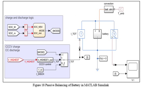
Fig. 18 displays the final Simulink model of a Passively Balanced, three module BMS. This system consists of various subsystems namely, Battery, Battery atmospheric temperature, Charge and Discharge Logic and Constant Current Constant Voltage (CCCV) Charge & Constant Current (CC) Discharge subsystem. Each subsystem performs a unique task to achieve its goal and contribute to the final calculation of the States of Battery pack parameters. The total number of cells balanced in this system are 192 cells.
- Steps involved in formation of BMS
Battery subsystem
a. STEP 1: Determination of the initial values of the Cell
- The initial stage of the battery module formation is done by addition of scripted table based battery of 3.7V. This battery is taken from the library of Simulink.
- The Fig below shows the block parameters that are already predefined in the script.
- The cell chosen for this project is similar to the cell specifications used in the Nissan leaf 2020.
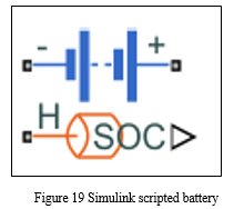
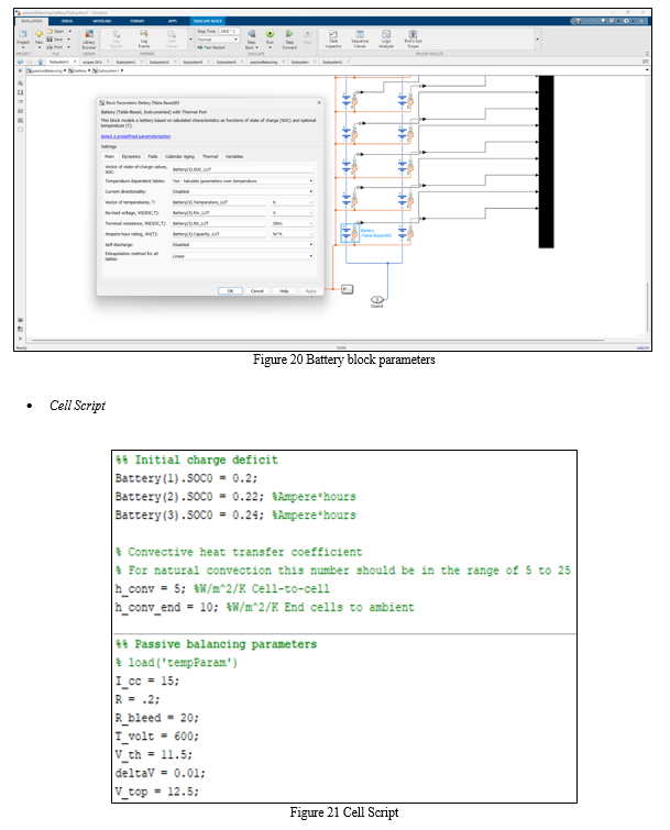
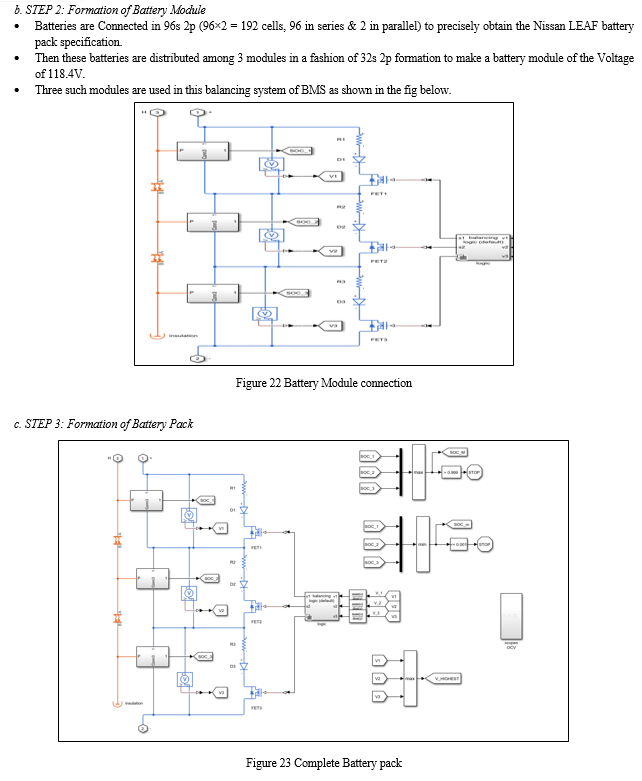
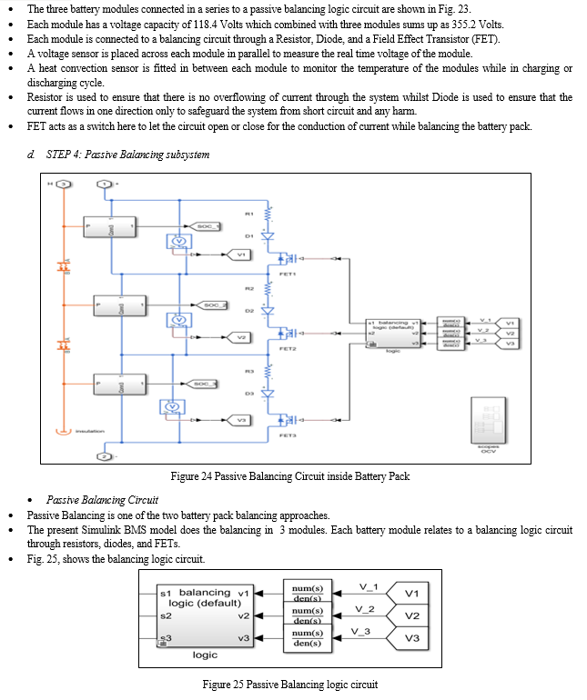
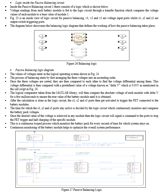
e. STEP 6: State of Charge comparator
- State of Charge of the three listed modules are compiled through a Multiplexer (Mux) in Simulink to compare with its maximum and minimum value. (Refer to Fig. 28)
- Max block compares the present SoC value to its predefined maximum SoC value of > 0.999, and Min block compares the present SoC value to its predefined minimum SoC value of <= 0.001.
- This step is performed to check whether the SoC value is at lowest limit or at maximum limit.
- Once the SoC value is obtained, this value is then fed to a SoC logic circuit which will be further discussed.
- Also refer to Fig. 23 to check the placement of SOC comparator.
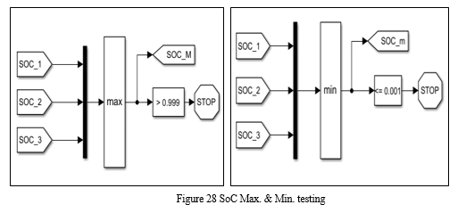
f. STEP 7: Voltage Comparator
- Each module’s voltage is measured through a voltage sensor giving us V1, V2 and V3.
- These three voltages are compiled and then compared to a predefined V_HIGHEST value which is mentioned in the cell script.
- Further the value is sent to the CCCV Charge and CC discharge block.
- There, V_HIGHEST value is fed into the CCCV block for analyzing the V_top value according to which current input (I_TOT) is set to charge the battery.
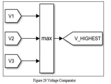
g. STEP 8: Charge and Discharge Logic
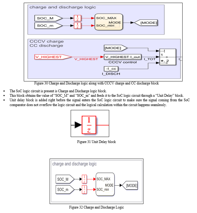
h. STEP 9: SoC Logic Circuit formation
- Fig. 33 shows the logic behind the SoC logic circuit which enables the charging or discharging mode for the described system.
- Firstly, the logic checks whether the SoC Max value is < 0.5 or not, if the condition satisfies then it switches on mode 1 to charge the battery.
- After opting for mode 1, the system halts for some time to let the battery charge, then again it checks the system for a condition, if the SoC Min is < 0.3, and if this condition satisfies then again mode 1 is turned on to keep on charging the battery.
- Secondly, it checks if the SoC Max is > 0.99, if this condition satisfies then the system opts for mode 2 to stop the charging process.
- This process is a continuous loop process, it ensures that the SoC of the battery stays above 0.3 and below 0.9 for a safe operating environment.
- Proper charging and discharging control also ensure that the battery does not heat up abnormally.
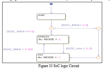
i. STEP 10: CCCV Charge and CC Discharge Block
- In the Constant Current Constant Voltage (CCCV) Charge and Constant Current (CC) Discharge Block, MODE is received from SOC logic comparator.
- The MODE defines whether the SOC is maximum or minimum as discussed earlier in step 8.
- I_cc is the constant current which is being fed directly by the predefined cell script.
- CCCV control subsystem (which is explained in Step 11) is responsible to deliver the desired current for the system to charge the battery pack.
- MODE, I_TOT and I_DISCH signals are sent to a multiport switch which decides whether to provide input current to the battery or not which is essential to charge the battery.
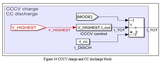
j. STEP 11: Constant Current Constant Voltage (CCCV) Control
- The precise current input is achieved through the Constant Current Constant Voltage Control logic block.
- The V_HIGHEST is passed through Unit Delay Block where it is compared with the condition <V_top.
- Further the signal heads to a summing point where the difference between the V_HIGHEST and V_top is taken and passed through a PID Controller.
- This PID Controller is a Proportional Integral Derivative Unit which is in a loop mechanism employing feedback from the output of multiport switch.
- The output from the PID controller is sent to a multiport switch which already has two more inputs (I_cc and the <V_top). On comparing the inputs from these three sources the multiport switch allows the I_cc to conduct current.
- From this, by using Output Port we get I_out.
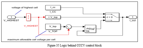
k. STEP 12: Temperature Control
- Charging and Discharging of any battery causes the temperature rise within the battery and the system.
- To simulate the temperature effect amongst the battery modules we have fixed a convective heat transfer sensor in between each module.
- The ambient temperature simulator is shown in Fig. 36, the role of this pulse generator is to generate a predefined base ambient temperature pulse i.e., 20°C for every temperature difference calculation.
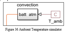
l. STEP 13: Convective Heat Transfer Sensor
- The convective heat transfer sensor senses the temperature between battery modules then compares the temperature value with the ambient temperature to get the exact temperature of the battery pack.
This is done to ensure that the battery pack temperature does not increase exponentially to cause any accident or harm to the occupants in an Electric vehicle.
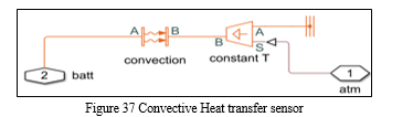
2. Result
a. Voltage and Current of single Cell
The voltage and Current of each cell can be observed in the graph w. r. t. time, during charging and discharging period. Voltage and current start off with considerably low values before charging as soon as the charging process starts the rise in values of voltage and current can be noted through graphs.
Charging of the cell will continue until it reaches its maximum safe limit, same is the case while discharging of cell takes place. The discharging will only happen until the lowest safe limit is reached.
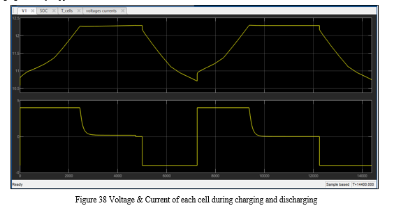
b. SoC of each Module
State of Charge of 3 modules can be observed in Fig. 39, while charging and discharging. At start each module has a different SoC, but as soon as the passive balancing circuit begins to balance the battery pack, almost all three modules now have the same SoC value.
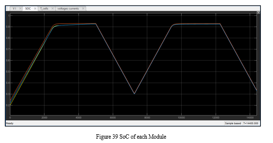
c. Temperature of Each Module
Three different temperatures can be observed in the following Fig. 40, each belongs to a separate battery module. Temperature values start at 20°C ambient temperature and then it increases as the battery tends to charge, one the contrary the temperature drops when battery stops charging and begins to discharge in a controlled manner.
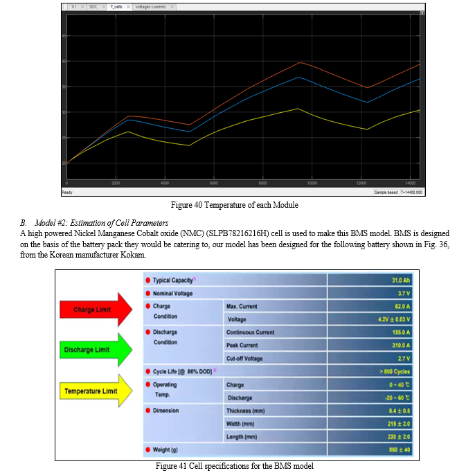
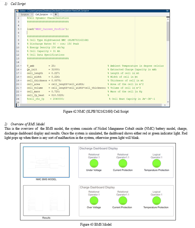
3) NMC BMS Model
The Nickel Manganese Cobalt oxide (NMC) BMS model acts as the brain of the system, this system is responsible for all the functioning of the BMS model. This model consists of logic for charging and discharging BMS.
The lithium ion cell models for discharge and charge models are connected to the discharge and charge BMS models .The input current which is taken from the cell script is supplied to two saturation blocks, one for the discharge current and the other for the charge current. The role of the saturation block is to divide the input current into positive and negative halves of current for discharge and charge respectively. The discharge current will be sent to the discharge BMS logic and charge current will be sent to the charge BMS logic. From this board BMS logic, we will get some controlled current which we will be sending back by using From and Go To block, which will go into the discharge cell model and charge cell model respectively.
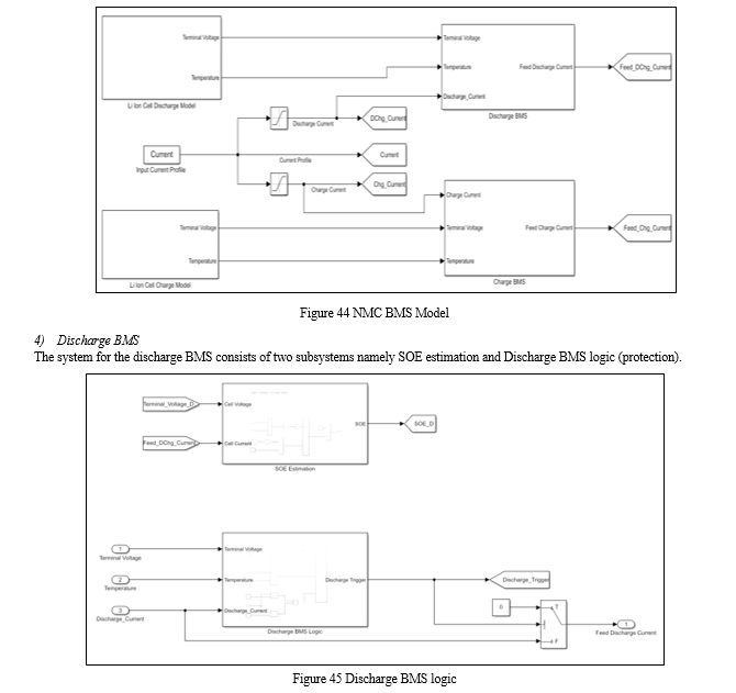
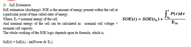
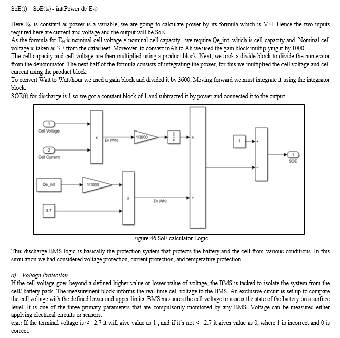
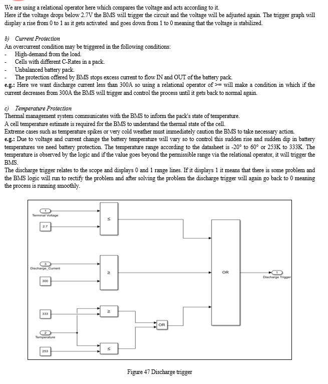
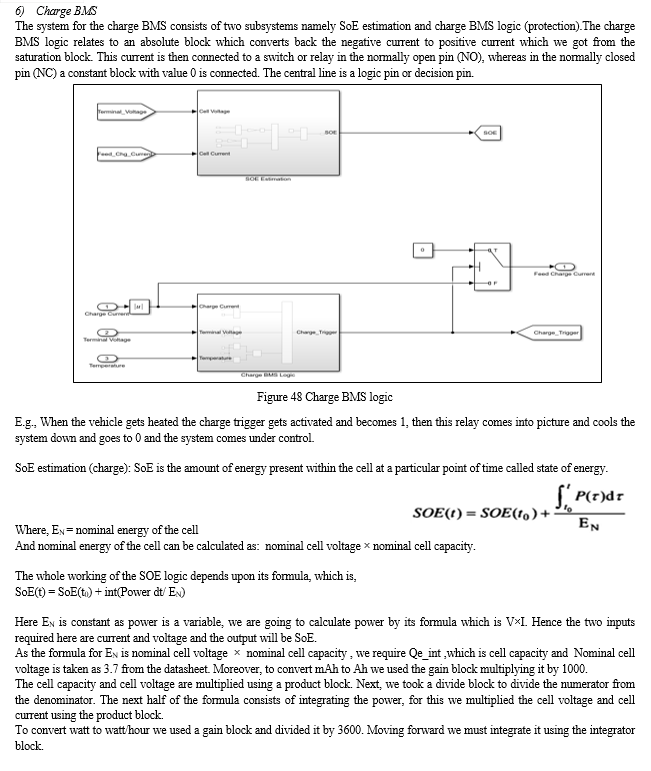
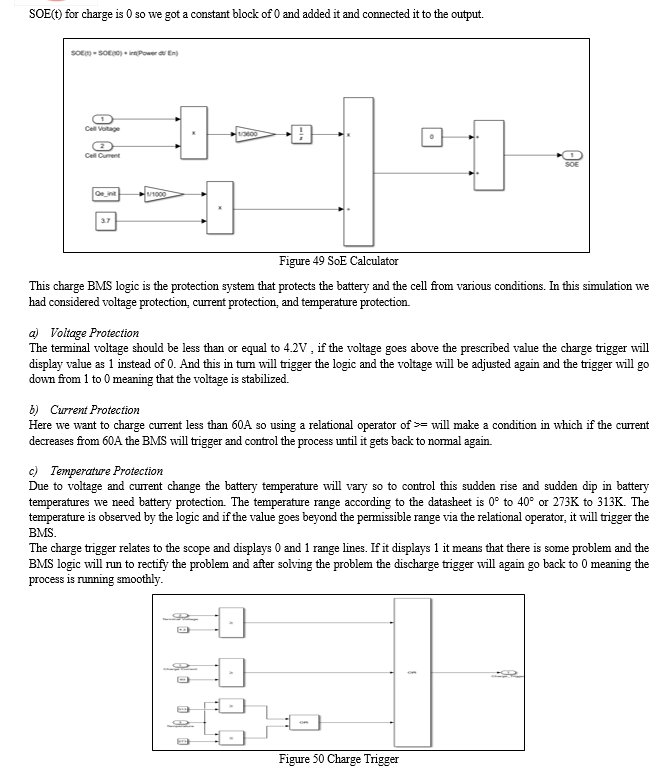
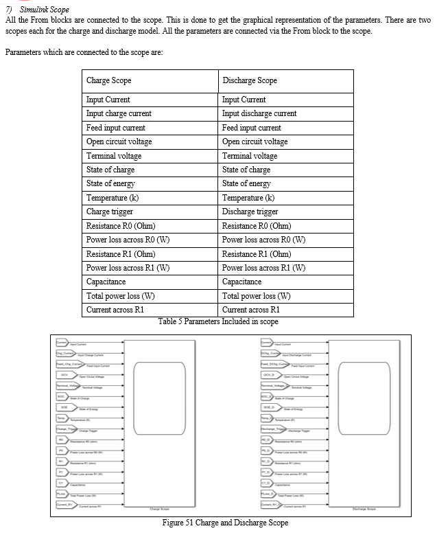
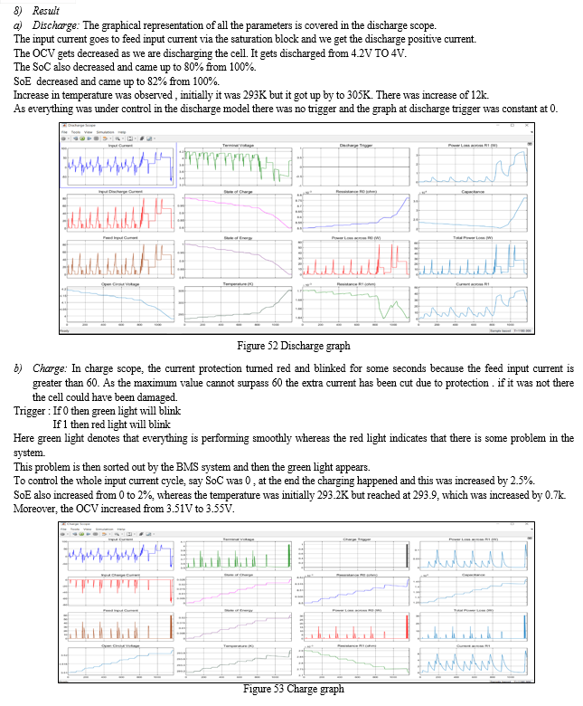
V. FUNCTIONS OF BMS
A. Battery Parameters Detection
This includes total voltage, total current and individual cell voltage detection (to prevent overcharging, over discharging and antipole), temperature detection, smoke detection, insulation detection, collision detection, impedance detection and so on.
B. Estimation of Battery States
This includes state of charge (SOC) or depth of discharge (DOD), state of health (SOH) and state of function (SOF). SOC or DOD of batteries is estimated according to such conditions as working current, temperature, and voltage. SOH is estimated according to the extent of abuse and performance degradation of batteries. SOF is estimated according to SOC, SOH, and operating environment of batteries.
C. On-Board Diagnosis (OBD)
The faults include sensor fault, actuator fault, network fault, battery fault, overvoltage (overcharge), undervoltage (over discharge), overcurrent, ultra-high temperature, ultra-low temperature, loose connection, exceeding combustible gas concentration, insulation fault, uniformity fault, over-fast temperature rise and soon.
D. Battery Safety Control and Alarm
This includes thermal system control and high voltage safety control. When the faults are diagnosed, the vehicle control unit or the charger will be informed through the network and they are required to handle the faults (when a certain threshold value is exceeded, BMS can also cut-off the battery power supply) to prevent damage to batteries or injuries to people caused by high temperature, low temperature, overcharge, over discharge, overcurrent, electric leakage and so on.
E. Charge Control
Based on the properties of its own batteries and the power level of the charger, BMS could control the charger to charge the batteries.
According to the information of each cell, BMS adopts such equalization methods as equalizing charging, dissipative equalization, or non-dissipative equalization to make the SoC between cells as consistent as possible.
F. Thermal Management
According to the temperature distribution within the battery pack and the requirements of charge or discharge, BMS decides whether to start heating or cooling as well as heating power and cooling power.
G. Networking
Since it is not convenient to disassemble BMS in a vehicle and meantime the vehicle is required to have network functions, it is desirable to conduct on-line calibrating and monitoring, automatic code generation and on-line program downloading (program update without disassembling the case) for BMS without disassembling the case. Usually the network CAN (Controller Area Network) is adopted.
VI. RESULTS AND DISCUSSION
Several SoC estimation methods are continually under investigation. Each has its merits and drawbacks. Therefore, some issues still need to be discussed in this section. The first issue is which method is more reliable and applicable considering all working conditions and full cycle life. The second issue is which method could be more promising with the rapid development of the battery chemistry, modeling, and management as well as the calculation speed and requirements of the estimation accuracy. We are yet unable to give a perfect answer, but some suggestions might be made according to the fore mentioned analysis.
A. Challenges in BMS
A literature review has revealed that BMSs are still in a premature stage. Even if state-of-the-art algorithms and monitoring methods were developed and applied in EVs, the reliability of BMSs would still make end users suspicious. Thus, the gap between the laboratory tests and the real requirements should be addressed by future research. Generally, the estimation and prediction methods have unfeasible hardware requirements, such as impedance measurement, which is costly and not practical in many BMS applications today.
Meanwhile, the high computational complexity depends on costly hardware, such as the central processor. It can be seen that the tradeoff between high performance and feasibility in a BMS is important.
As present scenario the charging time required is about 6 to 8 hours when normal charging is considered, which imposes another challenge of time management. While talking about fast charging this can go well under 90 minutes or less, but this depends on the availability of charging stations. DC charging points need charging infrastructure, which is yet another difficult to overcome. But some of leading EV companies across globe like Tesla, Nissan, Mahindra has taken initiative and also laid charging stations, moreover with the growth of battery applications, disposal and recycling problems also arise.
B. Cost
The cost of EVs is very high mainly due to the cost of Li-ion cells. The battery packs are imported and cost a lot, about $275/KWh in India. This combined with the GST of 18% and the lack of lithium in India, further increased the cost of batteries. In case of four wheelers, Most EVs in India provide a range of 200 to 250 km and cost between Rs 14-20 lakhs which does not give a cost advantage compared to higher range cars in the same price range.
VII. SCOPE OF BMS
Enhance the longevity of the Battery pack. A BMS with an accurate SoC estimation can prevent damage to the battery pack by triggering a cutoff under crucial conditions. Increases the performance of the battery pack. A BMS with an accurate SOC estimation can maximize the full potential of the battery pack capacity. Ensures the greater power system reliability of any battery-operated device.
Improves the battery power density in battery packs. The accurate SOC estimation allows battery packs to be designed accurately without being over-engineered which can result in smaller and denser battery packs. Achieves cost savings in smaller battery packs. To protect the cells and battery packs from being damaged. To make the batteries operate within the proper voltage and temperature interval, guarantee the safety, and prolong their service life if possible.
To maintain the batteries to operate in a state that the batteries could fulfill the vehicle’s requirements.
A. Battery Reuse
As counties race towards decreasing their greenhouse gas emissions, the public is being encouraged to use EVs by offering various incentives. As a result, the manufacturing of Lithium-ion (Li-ion) batteries is expected to increase very rapidly in the next few decades due to their expected use in electric vehicles. Battery packs used in electric vehicles are expected to be replaced when they reach about 80% of their original capacity, since range is an important quality in EVs. The batteries retired from the EVs are still an excellent medium of renewable energy storage in other applications, such as renewable energy storage systems.
Conclusion
Key technologies in the BMS of EVs have been reviewed in this project report, especially in the fields of battery modelling, state estimation and battery charging. Battery modelling together with the estimation of battery internal states and parameters play a vital role in revealing a hologram of battery operating status in the applications of EVs firstly. After capturing these key states, suitable battery charging approach can be designed to protect battery against damages, improve efficiency of energy conversion, and prolong the battery lifetime. However, most of the key technologies in the BMS are achieved and validated in specific test conditions. The modelling, estimation and charging performance in real world applications that would be different from the test conditions, or in a worst case scenario, is difficult to guarantee. Therefore, to explore the limitations or to develop a confidence interval of the present algorithms and approaches are required to tackle this challenging issue.
References
[1] Yuejiu Zhenga, Minggao Ouyangb, Xuebing Hanb, Languang Lub, Jianqiu Li, “Investigating the error sources of the online state of charge estimation methods for lithium-ion batteries in electric vehicles”, December 2017 [2] Hongwen He , Rui Xiong and Jinxin Fan, “Evaluation of Lithium-Ion Battery Equivalent Circuit Models for State of Charge Estimation by an Experimental Approach”, March 2011 [3] Rui xiong , Jiayi cao, Quanqing yu, Hongwenhe, and Fengchun sun, “Critical Review on the Battery State of Charge Estimation Methods for Electric Vehicles”, December 2016 [4] Dickson N. T., M. A. Hannan, M. S. Hossain lipu , and Pin jern ker, ”State of Charge Estimation for Lithium-Ion Batteries Using Model-Based and Data-Driven Methods: A Review”, September 2019 [5] Luca Buccolini, Adrianna Ricci, Cristiano Scavongelli, Giuseppe DeMaso-Gentile, Simone Orcioni, Massimo Conti, “Battery Management System (BMS) Simulation Environment for Electric Vehicles”, September 2016 [6] Kailong LIU, Kang LI, Qiao PENG, Cheng ZHANG, “A brief review on key technologies in the battery management system of electric vehicles”, April 2018 [7] Omkar S Chitnis, Dr.M.S.Sheshgiri, “A Review on Battery Management System for Electric Vehicles”, May 2019 [8] Languang Lua, Xuebing Hana, Jianqiu Lia, Jianfeng Huab, Minggao Ouyang, “A review on the key issues for lithium-ion battery management in electric vehicles” , 2012 [9] Balakumar Balasingam , Mostafa Ahmed, and Krishna Pattipati. “Battery Management Systems Challenges and Some Solutions” , 2020 [10] Bliss G. Carkhuff, Plamen A. Demirev , and Rengaswamy Srinivasan. “Impedance-Based Battery Management System for Safety Monitoring of Lithium-Ion Batteries”, 2018 [11] Seongyun Park,Jeongho Ahn, Taewoo Kang, Sungbeak Park,Youngmi Kim, Inho Cho, Jonghoon Kim,” Review of state-of-the-art battery state estimation technologies for battery management systems of stationary energy storage systems” , 2020 [12] Rui Xiong, Suxiao Ma, Hailong Li, Fengchun Sun, Ju Li, “Toward a Safer Battery Management System: A Critical Review on Diagnosis and Prognosis of Battery Short Circuit”, 2020 [13] Yuan Zou, Xiaosong Hu, Hongmin Ma Shengbo Eben Li, “Combined State of Charge and State of Health estimation over lithium-ion battery cell cycle lifespan for electric vehicles”, 2014 [14] JENS GROOT, “State-of-Health Estimation of Li-ion Batteries: Cycle Life Test Methods”, 2012 [15] Alberto Berrueta, Andoni Urtasun, Alfredo Ursúa, Pablo Sanchis, “A comprehensive model for lithium-ion batteries: from the physical principles to an electrical model” , 2016 [16] Elena Vergori, Francesco Mocera and Aurelio Somà, “Battery Modelling and Simulation Using a Programmable Testing Equipment”, 2018 [17] Manh-Kien Tran and Michael Fowler, “A Review of Lithium-Ion Battery Fault Diagnostic Algorithms: Current Progress and Future Challenges”, 2020 [18] Venkatesan Chandran , Chandrashekhar K. Patil, Alagar Karthick 3, Dharmaraj Ganeshaperumal, Robbi Rahim and Aritra Ghosh, “State of Charge Estimation of Lithium-Ion Battery for Electric Vehicles Using Machine Learning Algorithms”, 2021 [19] Mark Bowkett, Kary Thanapalan, Thomas Stockley, Mark Hathway, Jonathan Williams, “Design and Implementation of an Optimal Battery Management System for Hybrid Electric Vehicles” , 2013 [20] Yemeserach Mekonnen , Aditya Sundararajan and Arif I. Sarwat, “A Review of Cathode and Anode Materials for Lithium-Ion Batteries”, 2016 [21] https://batteryuniversity.com/article/bu-302-series-and-parallel-battery-configurations [22] https://www.dfrsolutions.com/blog/how-to-select-the-right-battery-for-your-application-part-1-battery-metric-considerations, Battery selection criteria [Accessed 21st August 2021] [23] https://en.wikipedia.org/wiki/Battery_management_system, Wikipedia [Online 2022] [24] https://in.mathworks.com/campaigns/offers/battery-management-systems-white-paper.html, MATLAB official website [Accessed 2021-2022] [25] https://lms.decibelslab.com, Decibles Lab a Bangalore start up course [Online 2022] [26] Manh-Kien Tran and Michael Fowler, “A Review of Lithium-Ion Battery Fault Diagnostic Algorithms: Current Progress and Future Challenges”, 2020 [27] Xiaopeng Chen; Weixiang Shen; Thanh Tu Vo; Zhenwei Cao; Ajay Kapoor, “An overview of lithium-ion batteries for electric vehicles”, 2012 [28] K.W.E. Cheng, Senior Member, IEEE, B. P. Divakar, Hongjie Wu, Kai Ding, and Ho Fai Ho “Battery-Management System (BMS) and SOC Development for Electrical Vehicles” October 2010 [29] V Karkuzhali, P Rangarajan, V Tamilselvi and P Kavitha “Analysis of battery management system issues in electric vehicles”, 2020
Copyright
Copyright © 2022 Pawaskar Gayatri Nilesh , Shaikh Anas Ahmed Atique , Saiyed Aman Nisar , Samal Deepak Kumar Ratnakar , Dr. Anup Narayan Chawan . This is an open access article distributed under the Creative Commons Attribution License, which permits unrestricted use, distribution, and reproduction in any medium, provided the original work is properly cited.

Download Paper
Paper Id : IJRASET47867
Publish Date : 2022-12-04
ISSN : 2321-9653
Publisher Name : IJRASET
DOI Link : Click Here
 Submit Paper Online