

Ijraset Journal For Research in Applied Science and Engineering Technology
Feasibility of a Thrust Control Mechanism by Regulating the Flow at the Engine
Authors: Deepak Kataria, Er. Ashok Kumar
DOI Link: https://doi.org/10.22214/ijraset.2022.44533
Certificate: View Certificate
Abstract
This work is focused on performance analysis of a turbojet engine with an inlet flow control mechanism for same thrust values. Developed a real-time turbojet engine integrating aerothermodynamics of engine components, principles of jet propulsion and inter component volume dynamics represented in 1-D non-linear unsteady equations. Performance parameters of the engine are analyzed with the increase in compressor pressure ratio. Specific fuel consumption, specific thrust, component pressure ratios, thermal and propulsive efficiencies are the performance parameters of the engine that are analyzed on the model with reduced inlet pressure. All simulations will be done on MATLAB Tool.
Introduction
I. INTRODUCTION
Jet engines are noticeably non-linear flowers with a complex range of operation defined through a flight envelope. Altitude and Mach amount defines the operational set elements for the engine. The important venture for these structures is the manufacturing of properly enough thrust whilst maintaining safe and strong operation. Performance requirements for the engines vary in accordance to challenge characteristics.
Civil plane operation requires minimum jogging and renovation fees.
A complete mathematical description of a gas turbine engine is especially complex and in particular nonlinear. The manage synthesis system is primarily based on the selection of a set of format fashions that may also be used to formulate a manage regulation for software at some point of the engine running variety. Therefore a crucial step inside the manage design way is the era of tractable layout models. Linear fashions are one elegance of such layout models and can be effectively integrated to offer a nonlinear manage feature.
A. Model Reduction
Once nonlinear engine dynamics has been linearised, some approach may be required to investigate the linear models and set up much less complex layout fashions which consist of great dynamic factors crucial to the favoured control feature. Without such simplification, design can also want to bring about pretty complex and parameter sensitive controlled systems.
B. Control Mode and Structure Analysis
Once nonlinear engine dynamics has been linearised, some approach may be required to investigate the linear models and set up much less complex layout fashions which consist of great dynamic factors crucial to the favored control feature. Without such simplification, design can also want to bring about pretty complex and parameter sensitive controlled systems.
In Survey, Turbofan Power Ratio have become used as thrust parameter in turbofan engines with ordinary consistent nozzle production, and the writer confirmed the applicability of this parameter to turbojet engines with steady exhaust, therefore, it became a herbal sequel to research the variable nozzle configuration. The author finished measurements on a turbojet engine geared up with variable exhaust nozzle, and the facts confirmed distinct linear correlation between thrust and TPR relying on actual nozzle function putting.
Because the particular definition of TPR caused unbiased capabilities as opposed to a single expression, the author has evolved a manner to gain an equal overall performance parameter that adjustments linearly with thrust output of the engine and it's miles independent of the real situation of the nozzle.
This work is introduced as pursues. In Section II, It defines the function of turbojet engine. Section III portrays the proposed methodology of system. The performance parameters are described in Section IV. The results are explained in Section V. At last, conclusion is clarified in Section VI.
II. TURBOJET ENGINE
Jet Engine is the gas turbine application for aircraft propulsion. Basic principle in a jet engine is to accelerate a mass of fluid within the path opposite to motion and thereby propelling the aircraft beforehand via using the thrust generated. Schematic variations the various Turbojets, Turbofans and Turboprop/Turbo shaft Engines are defined here. Turbojet is the earliest and only shape of jet engines and produce thrust by using significantly accelerating a small mass of fluid. Figure 1 indicates a conventional unmarried spool turbojet above the centre line, and one with the addition of an afterburner, convergent–divergent consumption, and nozzle underneath the centre line. Ambient air passes from unfastened flow to the flight consumption predominant component and the air hastens from unfastened flow if the engine is static, at the same time as at high flight Mach wide range it diffuses from the unfastened movement, ram situations. Usually, it then diffuses inside the flight intake earlier than passing through the engine consumption to the compressor face with a small loss in widespread pressure. The compressor then will increase both the stress and temperature of the gas. Work input is required to benefit the pressure ratio; the related temperature rise relies upon at the performance of the compressor.
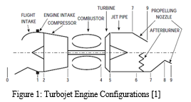
The compressor exit diffuser passes the air to the combustor. Here, gasoline is injected and burnt to enhance exit fuel temperature. The diffuser and combustor every impose a small standard stress loss. The heat, excessive stress gasoline is then expanded via the turbine in which art work is extracted to produce shaft electricity; each temperature and strain are reduced. The shaft power is that required to electricity the compressor and any engine auxiliaries. On leaving the turbine, the fuel is nevertheless at a stress commonly at least times that of ambient. This results from the higher inlet temperature to the turbine. Downstream of the turbine the fuel diffuses in the jet pipe.
This is a brief duct that transforms the glide direction from annular to a complete circle at get admission to to the propelling nozzle. The jet pipe imposes a small total strain loss. The propelling nozzle is a convergent duct that quickens the drift to provide the immoderate velocity jet to create the thrust. Engine cooling system uses the pretty cool air from the compression system that bypasses the combustor through air device waft paths to relax the turbine nozzle guide vanes and blades to ensure best steel temperatures at prolonged fuel temperatures.
For high flight Mach amount programs an afterburner is frequently employed, which gives produces higher thrust from the identical configuration. This is also referred to as reheat, and involves burning gasoline in a further combustor downstream of the jet pipe. Turbojets are pretty inefficient in assessment to exclusive engine sorts at decrease Mach numbers but has dominant feature for the supersonic flight modes and navy applications. Turbofans are widely used engines for the contemporary civil-aircraft propulsion. A turbofan engine is based totally definitely on the principle that for the equal strength, a large volume of slower-moving air will produce extra thrust than a small quantity of speedy-moving air. Turbofan engines are of the types separate jets turbofan and combined turbofan with afterburner. Figure 2 indicates the configuration of the separate jets turbofan above the centre line and combined turbofan with afterburner beneath the centre line.
III. PROPOSED METHODOLOGY
The main objective of this work is to analyze the feasibility of a thrust control mechanism by regulating the flow at the engine inlet. For the proper jet engine, paintings executed on the turbine is thought to be same to the compressor work and the techniques in the diffuser, the compressor, the turbine and the nozzle are assumed to be isentropic. So the internet artwork carried out in a turbojet engine is 0. However, for the real cycle assessment, the irreversibility related within the compressor, turbine, nozzle and diffuser ought to be considered. Therefore, in a consistent united states operation of the jet engine, the turbine and the compressor paintings have to be same. Any distinction in those parameters runs engine into the transient mode of operation.
A mathematical model, based on the lumped parameter technique is used from the unsteady one dimensional conservation laws defined via a set of first-order differential and algebraic equations.
A. Surrounding Atmosphere Model
The air flowing into the engine diffuser is taken from the out of doors surroundings. Ambient air temperature and strain are decided through the altitude.
B. Inlet
Intake diffuser is used to hold the loose flow into air into the engine. It does not paintings at the glide and publications the flow to the compressor. However, the overall performance of the inlet is defines through the stress healing from the loose flow into to the engine. An isentropic technique is assumed for the air go together with the glide in the inlet diffuser. Heat transfer and the friction among the air and the diffuser walls are not considered. Also the go with the flow in the diffuser is modelled as a quasi consistent country and so the dynamic conduct of the air inside the diffuser isn't always considered.
C. Compressor
The reason of a compressor is to growth the overall stress of the gas waft to that required through the engine at the same time as absorbing the minimum shaft power feasible. Temperature of the incoming air additionally will increase with stress in the compressor. The artwork completed via the compressor at the gasoline is extracted from the turbine. In the reference engine model, the compressor is an axial compressor with eight levels. But while modelling the engine in Simulink, compressor is modelled as a unmarried block with the useful resource of stacking all of the stages of the compressor right into a unmarried block. The pressure ratio and performance are normally regarded up from a tabulated compressor overall performance map, however they also can be assigned right away inside the model. Compressor general overall performance maps deliver pressure ratio and efficiency as capabilities of corrected air go together with the go with the flow and corrected shaft velocity.
D. Compressor Map
Compressor normal overall performance maps are acquired from the real rig take a look at of the engines and plotting the results on the map. Compressor map are plotted among the corrected drift parameter and stress ratio with corrected velocity lines. Efficiency contours might be at the identical plot or separated onto any other plot among overall performance and pressure ratio with corrected velocity strains.
E. Combustor
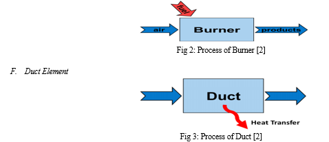
The Burner detail calculates standard overall performance of a general gasoline turbine burner/combustor. This element accepts an air movement from the compressor and a gasoline move from the Fuel Start element as established in Fig 2.
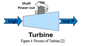
The Duct element calculates strain and warmness losses through ducts as validated in Fig 3. Pressure and warmth losses are each enter as person-defined fractional losses or via character described calculation capabilities. The warm temperature loss thru the duct is idea to be negligible.
G. Turbine
The Turbine element (Figure 4) expands and extracts paintings from the core go with the flow of the fuel turbine. As with the Compressor element, the pressure ratio and efficiency for the turbine are either regarded up in a tabulated turbine overall performance map or assigned right away through the consumer.
H. Nozzle Element
The Nozzle detail calculates the overall performance of the gasoline turbine’s nozzle. This element determines overall performance tendencies for excellent nozzle geometries (convergent, convergent-divergent, fixed, or variable geometry). In on design mode, if the nozzle isn't always choked, the nozzle exit region is calculated such that the calculated exhaust static stress equals the specified exhaust static strain.
IV. PERFORMANCE PARAMETERS
The universal overall performance parameters for an aero-engine are defined on this phase. Each parameter has explains the significance associated with turbojet engine.
A. Specific Thrust
This is the quantity of output thrust in line with unit of mass waft getting into the engine. It is mainly crucial to maximize specific thrust in packages wherein engine weight or quantity is crucial for plane that fly at excessive Mach numbers wherein the drag in keeping with unit frontal vicinity is excessive.
B. Specific Fuel Consumption
This is the mass of gasoline burnt in step with unit time consistent with unit of output energy or thrust. It is vital to reduce SFC for packages in which the load and/or value of the gas are big. When specifying the SFC values, it's far crucial to state whether or no longer the decrease or better calorific charge of the gas is used.
C. Thermal Efficiency
Thermal performance for jet engines is defined as the price of addition of kinetic electricity to the air divided with the useful resource of the price of gasoline power furnished, commonly ex pressed as a percent.
D. Propulsive Efficiency
Propulsive performance for jet engines is defined as the useful propulsive power produced by way of way of the engine divided with the aid of the fee of kinetic energy addition to the air, once more commonly expressed as a percent. The net thrust is proportional to the difference within the jet and flight velocities.
V. RESULTS & DISCUSSION
Ambient Air |
Inlet |
Compressor |
Combustor |
Turbine |
Nozzle |
Figure 5: Turbojet Engine Modelling
Although the solver configuration is exclusive among the first and 2D layout instances, it's miles essential to notice that the converged answers are the identical. The input parameters for both layout instances are defined in the following phase. The design case parameters are described for full throttle operation. The enter values of ambient stress, ambient temperature, engine velocity, thrust, Mach wide variety, compressor strain ratio, fuel waft price, burner pressure loss, and turbine stress ratio are decided experimentally.
A. Results with Converging Nozzle
It is critical to word that the engine version is fixed for the off-layout evaluation in line with the converged answer of the design evaluation. This manner performance is calculated using the identical rapid machinery overall performance maps and geometric engine parameters for every case. The purpose of a compressor is to boom the full strain of the fuel flow to that required through the engine even as absorbing the minimal shaft energy possible. Temperature of the incoming air also will increase with strain in the compressor. The work carried out by the compressor at the fuel is extracted from the turbine.
B. Results with Mixing Turbofan after Burner
In the temporary procedure, the compressor is modelled as a blending extent wherein the mass and power may be accumulated. The fuel dynamics associated inside the compressor degrees are calculated by using applying the continuity, power and Ideal gas equations to the inter element extent between the compressor and the combustor. Table 1 indicates the Input Parameters of System after Burner.
Table 1: Input Parameters of System after Burner
Parameter |
Air |
Burner |
After Burner |
Ratio of Specific Heat |
1.4 |
1.33 |
1.3 |
Specific Heat at Constant Pressure |
1004 |
1156 |
1243 |
Fuel Lower Heating Value |
0 |
42000 |
42000 |
Unlike the theoretical combustion technique where the inlet pressure and outlet strain of the chamber are same, there is a pressure drop in the combustion for the actual method.
A convergent nozzle is considered in modelling the engine. The partly accelerated gas coming from the turbine at a especially high pressure is improved to a excessive velocity inside the nozzle. Finally, the gases extend to the ambient strain and offer the thrust to propel the aircraft.
Conclusion
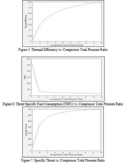
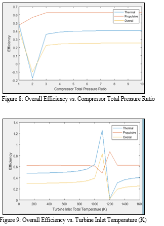
With the known values of the altitude, the working Mach and decided on values of the shaft rotational pace, mass float parameter for the compressor, values for the compressor stress ratio, efficiency is cited from the values of the performance map. Overall performance of the turbojet engine decreases with reduced compressor inlet stress for the equal thrust if the engine is operated constantly with this mechanism. But has big importance for packages in which a certain amount of efficiency might be spent for the electricity demands. Performance parameters of the engine are analyzed with the increase in compressor pressure ratio. Specific fuel consumption, specific thrust, component pressure ratios, thermal and propulsive efficiencies are the performance parameters of the engine that are analyzed on the model with reduced inlet pressure
References
[1] L. Baoan, Z. Fan, (2012), \"Modeling and Simulation of Small Turbojet Engine Ground Starting Process\", International Conference on Instrumentation & Measurement, Computer, Communication and Control, pp. 28-32. [2] Z. Katolický, B. Bušov and M. Bartlová, (2014), \"Turbojet Engine Innovation and TRIZ\", IEEE, pp. 01-08. [3] L. Nyulászi, L. Madarász, (2014), \"Experimental Identification of the Small Turbojet Engine MPM-20\", IEEE International Symposium on Computational Intelligence and Informatics, pp. 497-501. [4] Ján Hrabovský, Rudolf Andoga, Ladislav Fozo, (2015), \"A Conceptual Method For Implementation of Anytime Algorithms For A Small Turbojet Engine \", IEEE International Symposium on Computational Intelligence and Informatics, pp. 113-116. [5] D. Klein, C. Abeykoon, (2015), \"Modeling of a Turbojet Gas Turbine Engine \", IEEE, pp. 200-206. [6] N. Mubarak, S. Farooq, (2015), \"Feasibility to Adapt Modifications in the Extant Turbojet Engine Test Bed for the Ground Test Run of Turbofan Engine\", IEEE, pp. 01-06. [7] D.Bai, Q. Zheng, (2017), \" Influence of Wet Compression on Operating Performance and Exhausts of Turbojet Engine\", International Conference on Computation of Power, Energy, Information and Communication, pp. 477-485. [8] V. Kuz\'michev, A. Tkachenko, (2017), \"Optimization of Working Process Parameters of Small-scale Turbojet for Unmanned Aircraft\", International Conference on Mechanical, System and Control Engineering, pp. 125-129. [9] O. Turan, A. Hepbasli, (2017), \"Investigating the Effect of Turbine Inlet Temperature on the Exergetic Improvement Potential of a Small Turbojet Engine\", International Conference on Mechanical and Aerospace Engineering, pp. 301-304. [10] K. Yuan, C. Chun, (2018), \"Performance Calculation and Integrated Mission Assessment of High Speed Turbojet-Scramjet Combined Engine\", International Conference on Mechanical and Aerospace Engineering, pp. 168-172. [11] I. Goryunov, M. Muraeva, (2018), \"Mathematical Modelling of In-turbine Isothermal Expansion in the Gas Turbine Engine\", International Russian Automation Conference, pp. 01-05. [12] J. Xiang, C. Chun, (2019), \"Adaptive Simulation of Micro-Turbojet Engine Component Characteristics\", IEEE International Conference on Mechanical & Aerospace Engineering, pp. 147-152. [13] I. A. Krivosheev, A. E. Kishalov, (2019), \"Analysis of Options for Converting Aviation Two Spool Turbojet Engines with Afterburner when Developing Gas–Turbine–Driven Compressor Plant for Gas–Compressor Unit\", International Russian Automation Conference, pp. 01-06. [14] A. Shehata, M. Khalil, (2020), \"Controller Design for Micro Turbojet Engine\", IEEE, pp. 436-440. [15] Flyur Ismagilov, Vyacheslav Vavilov, (2020), \"Design of the “Integrated Into An Aircraft Engine Starter-Generator- Dual-Flow Turbojet Engine” System As A Part Of The Electrified Aircraft Engine\", IEEE Explore, pp. 01-06. [16] K. Beneda, (2021), \"Investigation of Novel Thrust Parameters to Variable Geometry Turbojet Engines\", IEEE World Symposium on Applied Machine Intelligence and Informatics, pp. 339-341.
Copyright
Copyright © 2022 Deepak Kataria, Er. Ashok Kumar. This is an open access article distributed under the Creative Commons Attribution License, which permits unrestricted use, distribution, and reproduction in any medium, provided the original work is properly cited.

Download Paper
Paper Id : IJRASET44533
Publish Date : 2022-06-19
ISSN : 2321-9653
Publisher Name : IJRASET
DOI Link : Click Here
 Submit Paper Online