

Ijraset Journal For Research in Applied Science and Engineering Technology
Radio Over Fiber System for A Four-Store Hospital Building
Authors: Taiwo Samuel Aina, Oluwaseun Olanrewaju Akinte, Babatunde Ademola Iyaomolere, Uyi Aiyudubie Samson, Abode Innocent Iriaoghuan, Emmanuel Ademola
DOI Link: https://doi.org/10.22214/ijraset.2022.39842
Certificate: View Certificate
Abstract
The goal of this project is to design and analyse a radio over fibre system for a four-story hospital with 20 rooms on each floor. The number of ONUs per floor is 20, and it was assumed that each room had an ONU capable of providing network access to voice, data, video, and biometrics. We build an 80-channel WDM optical transmitter using the WDM method. The proposed system includes a transmitter with 20 input channels, a multiplexer, a DE multiplexer, a 45-kilometer optical fibre, and an amplifier. The proposed model was simulated, and the results were evaluated in WDM systems using an optical amplifier. The receiver performance analysis of the Optical Communication System is shown by the BER simulation run and the eye diagram graphic, with the threshold set at 0.00120739. Furthermore, the eye height is 0.00141402, and the minimum BER is 5.59009e-006. When the simulated and calculated values of received power and total power loss are compared, the system is efficient.
Introduction
I. INTRODUCTION
Fiber-optics, which was first created in the 1970s and has transformed the telecommunications sector due to its advantages. These advantages include ability to be almost noise free, small diameter and thinner than copper as is composed of glass making it easier to install and considerably increased capacity. Optical fibres are used in a variety of applications, including telephone systems, submarine cable networks, computer networks data links, hospitals and many other applications in the industry. Because multimode fibres have a big diameter, they can easily couple more light into them. Multimode step index multimode fibres make up the majority of the plastic fibres. Radio over Fibre technology (RAUs) encompasses using optical fibre cables to transmit RF signals from a central site to Remote Antenna Units.
Dedicated indoor radio systems are an efficient solution to deliver enhanced in-building coverage and capacity in public spaces, such as office buildings [3]. Due to the enormous bandwidth, ultra-low attenuation, immunity to electromagnetic interference, and low cost of optical fibre, radio-over-fibre (RoF) technology has been regarded as the preeminent solution for implementing mobile fronthaul (MFH) in micro/picocell network designs[1]. Linearity and noise concerns beset analogue optical transport, hence digital alternatives are preferred by the industry. Radio frequency (RF) transfer over analogue intensity-modulated direct detection optical fibre lines has long been associated with RoF, which has been justified by cost savings [2]. WDM (Wavelength Division Multiplexing) is the fundamental technology of optical networking, and it is a way for transporting several separate and independent optical channels over a single fibre [4]. The optical modulation of RF signals, notably in the microwave and millimeter-wave bands, as well as other parameters, impact the performance of a RoF link [5].
II. LITERATURE REVIEW
In [6] examined the key role parameter players in reducing influence of NLD on the Radio over fibre link. On the OptiSystem platform, the simulation was conducted. Electrical cancellation point, output power, oscilloscope visualizer, modulation kinds, and laser power, among other things, are used to investigate the nonlinear effect. The NLD effect reduces the amplitude of the output signal by 97 percent, whereas increasing the laser power increases the output power by 76 percent. The nonlinear distortion impact has also been significantly reduced as a result of the modulation order.
[7] research on Optical Link Performance Analysis Using EDFA. The optimal results of gain, output power, BER, and Qfactor were reached by properly choosing input power, pump power, EDF length, and erbium ion concentration. The software optisystemv13 was used to obtain the results. They develop and simulate a DWDM system with 320 Gbps data rate over 70 kilometres of fibre in their study. With 344% gain flatness from 1527 nm to 1552 nm bandwidth, the system for 32channel amplification was investigated. For a value of -25 dBm, the best gain values were found. All of the measurements were done at a wavelength of 980 nm and a fibre length of 70 km. The amplification technique yielded superior results. [8] explored the optical amplifier operating parameters by simulating EDFA amplifiers with varied fibre lengths. [9] employed EDFA to enhance multi-channel DWDM signals. In [3] research on performance of WDM and EDFA, he came to the conclusion that the ideal wavelength for use in a WDM system is 1532.68 nm.
III. DENSE WAVELENGTH DIVISION MULTIPLEXING (DWDM)
DWDW transmits data over long distances and is used to boost bandwidth over existing fibre networks by mixing and sending signals at various wavelengths over the same cable at the same time. Passive DWDM and active DWDM are two types of DWDM. Active DWDM, as shown in the block diagram below, is a method of transporting massive volumes of data between locations in a data centre interconnect setup
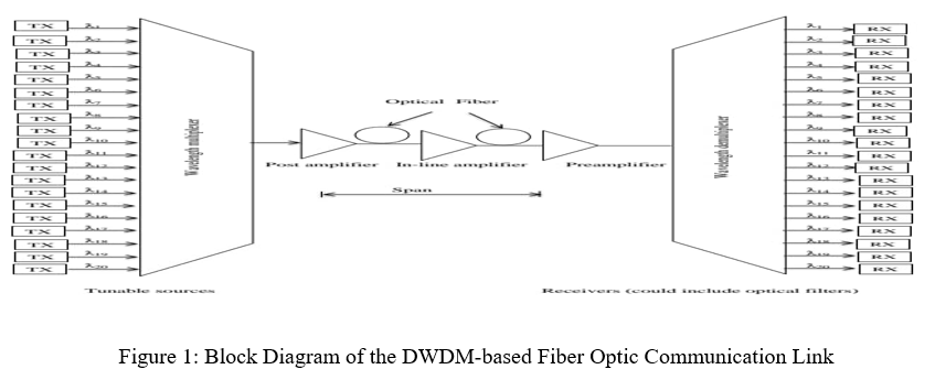
IV. DWDM BLOCK DIAGRAM COMPONENTS DESCRIPTION
- Transmitters: The source signals are provided by transmitter, which are multiplexed afterward.
- Receivers: The receiver detects light pulses and converts the incoming optical signal to electrical form.
- DWDM Multiplexer: The DWDM multiplexer mixes several wavelengths generated by multiple transmitters on separate fibres.
- DWDM Demultiplexer: At the receiving end, the DeMux (demultiplexer) separates all of the individual wavelengths of the composite signal out to individual fibers.
- Optical Fibre: Optical fibres are employed to convey light between the fiber's two ends .
- Inline Amplifiers: The distance between regenerative repeaters is increased by using an inline optical amplifier to compensate for transmission loss.
- Pre Amplifiers: With preamplifiers a weak received optical signal is amplified before photo detection
V. DETAILS OF THE HOSPITAL BUILDING
Number of Floors: 4 Floors
Number of Rooms per Floor: 20 Units
A. Assumptions
Number of ONUs per floor: 20; It is assumed that an ONU capable of providing network access to voice, data, video and biometrics is installed in each room.
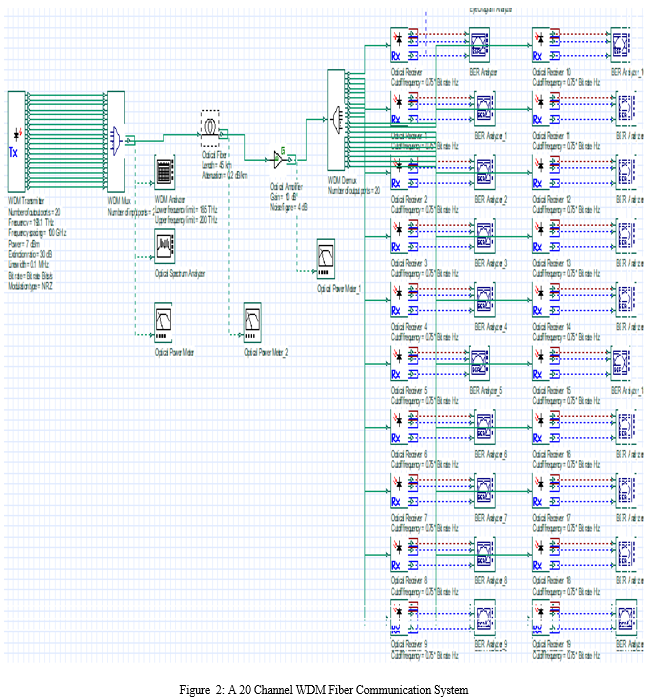
Using the WDM method, we implement an 80 channel WDM optical transmitter.
The purpose of using WDM approach is to save the cost of installation of many fiber cables and so with just one fiber cable, a large number of channels can be multiplexed into the fiber cable link.
VI. SYSTEM PERFORMANCE ANALYSIS
The system specification is shown in the table below
Table 1: Link Budget Design Parameters
|
Parameter |
Value |
|
Operating Wavelength |
1550 nm |
|
Maximum Output Optical Power |
7.00 dBm |
|
Minimum Receiver Sensitivity |
-28 dBm |
|
Optical Fiber Type |
Single Mode |
|
Fiber Optic Span |
45 km |
|
Attenuation |
0.22 dB/km |
|
Number of output ports |
20 Channels |
|
Frequency Spacing |
100 GHz |
|
Optical Transmit Power |
7 dB |
|
Extinction Ratio |
30 dB |
|
Modulation Type |
NRZ |
|
Numbers of connectors |
4 |
|
Splice loss |
0.1dB |
|
Connector loss |
0.75dB |
|
Safety margin |
3.0dB |
.
System Link Budget = [fiber length (km) × fiber attenuation per km] + [splice loss × number of splices] +[connector loss × number of connectors] + [safety margin] ………………… [10]
Link Budget= [45km × 0.22dB/km] + [0.1dB × 4] + [0.75dB × 4] + [3.0dB] = 16.3dB
Therefore, System Link Budget is 16.3dB
VII. IMPLEMENTATION OF THE SYSTEM IN OPTI WAVE
Single mode fibre is chosen in this design because it has a faster data rate, less dispersion, and can function over extended distances. Optisystem 18.0 was used to simulate the designed system, which transports information through optical carrier waves from the transmitter to the receiver via optical fibre.
VIII. SYSTEM ANALYZER
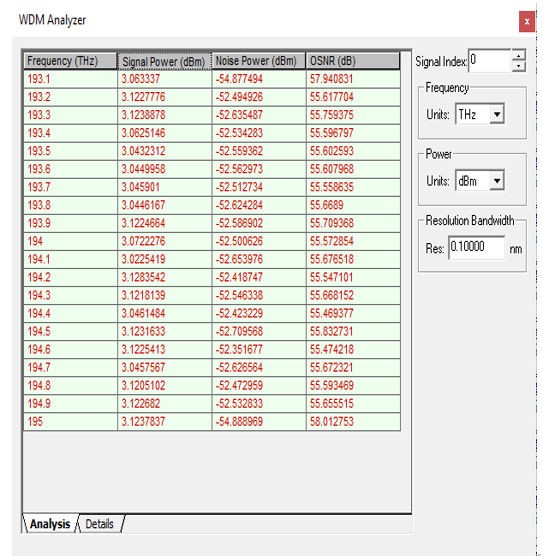
Figure 3: The WDM Analyzer result at the output of the WDM Optical Multiplexer
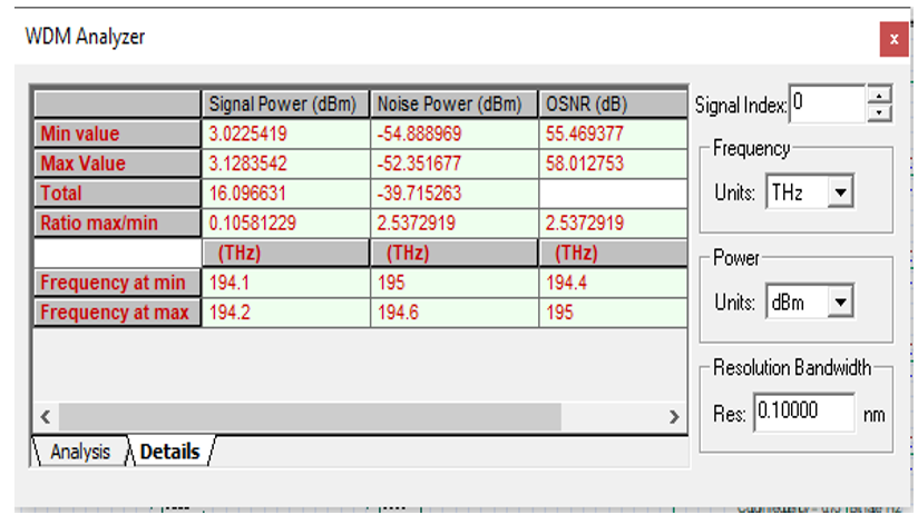
Figure 4: The WDM Analysis summary at the output of the WDM Optical Multiplexer
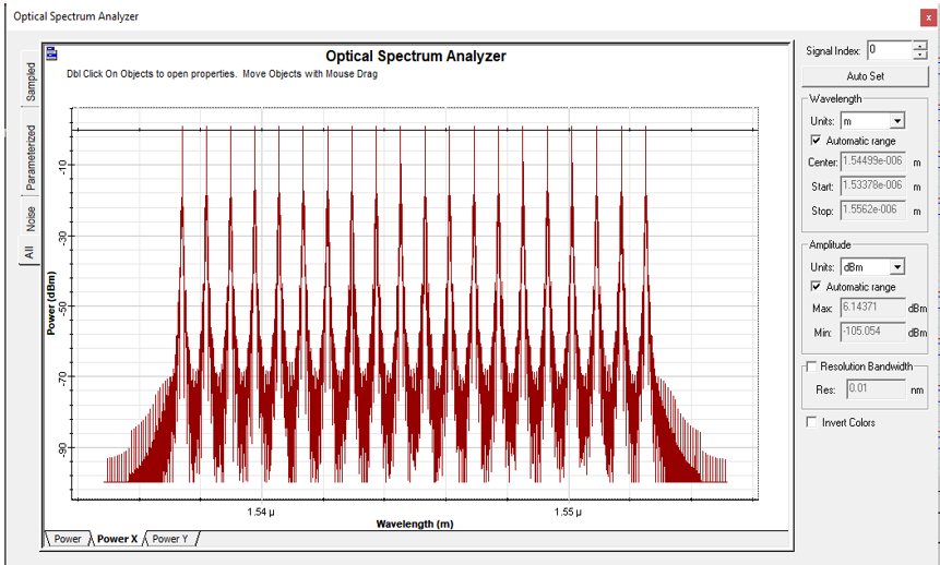
Figure 5: The Optical Spectrum Analysis at the output of the WDM Optical Multiplexer
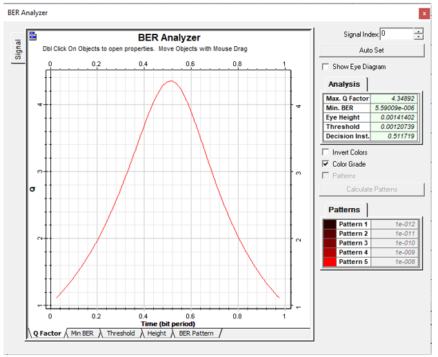
Figure 6: The Q Factor Curve from the BER Analyzer at the Optical Receiver for CH 1
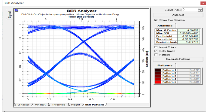
Figure 7: The Eye Diagram of the Optical communication system for CH 1
The parameter settings were graphically examined to get the best values. The proposed system includes a transmitter with 20 input channels, a multiplexer, a demultiplexer, a 45-kilometer optical fibre, and an amplifier. The proposed model was simulated, and the results assessed . The receiver performance analysis may be seen in the BER simulation run and the eye diagram diagram.
From the diagram figure 3.7 for Channel 1, the Max Q-factor is 4.34892 while the threshold is 0.00120739. Also, the minimum BER is 5.59009e-006 and the Eye height is 0.00141402.
IX. COMPARISON OF THE DESIGNED SYSTEM'S PERFORMANCE WITH SIMULATION RESULTS
Comparing the simulated and calculated values of the received power and total power loss shows that the system is efficient and they are as shown below:
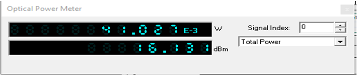
Figure 3.8: The Power Output of the Optical Multiplexer
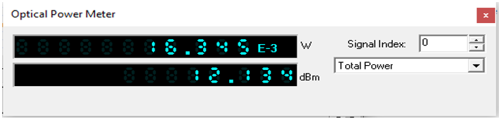
Figure 3.9: The Power Input to the Optical Demultiplexer

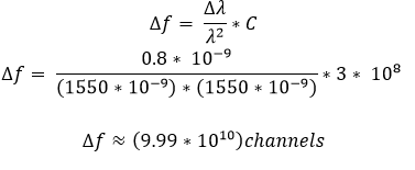
X. NUMBER OF CHANNELS THE SYSTEM CAN ACCOMMODATE TO THE MAXIMUM
To determine the maximum number of channels that can be accommodated in the system;
Conclusion
The system has been designed and simulated based on specification. The BER simulation run and the eye diagram graphic show the receiver performance analysis.of the Optical Communication System, while the threshold is 0.00120739. Also, the Eye height is 0.00141402 and the minimum BER is 5.59009e-006. The system is efficient when the simulated and calculated values of received power and total power loss are compared.
References
[1] Farghal, \"Joint impact of fibre dispersion and frequency chirp on MCF?based radio?over?fibre mobile fronthaul\", IET Optoelectronics, vol. 14, no. 4, pp. 189-198, 2020. Available: 10.1049/iet-opt.2019.0051. [2] T. Hall, F. Lucarz, J. Mitchell and P. Pajusco, \"Radio-over-fibre for green wireless access networks\", annals of telecommunications - annales des télécommunications, vol. 68, no. 1-2, pp. 1-2, 2012. Available: 10.1007/s12243-012-0350-7. [3] K. Persson et al., \"WCDMA radio-over-fibre transmission experiment using singlemode VCSEL and multimode fibre\", Electronics Letters, vol. 42, no. 6, p. 372, 2006. Available: 10.1049/el:20064130. [4] Ismail M.M et al,“Performance Analysis of WDM and EDFA in C-band for optical communication system”, IJRRAS, Vol. 13, Issue 1, October, 2012 [5] J. Ye, L. Yan, A. Li, X. Chen and W. Shieh, \"Performance improvement of double-sideband signals in radio-over-fiber links utilizing pre-distortion method\", Optics Express, vol. 22, no. 3, p. 2185, 2014. Available: 10.1364/oe.22.002185. [6] Ajay Kumar, Vyas Navneet, Agrawal Suriti Gupta, “Investigation the Effect of Nonlinear Distortion for Radio over Fiber, ” International Journal of Emerging Trends & Technology in Computer Science (IJETTCS). Volume 1, Issue 2, July – August 2012 ISSN 2278-6856 [7] Bhumika A. Patel, Prof. Ankit Patel , “Performance Analysis of Optical Link using EDFA, ” IJSRD - International Journal for Scientific Research & Development| Vol. 3, Issue 03, 2015 | ISSN (online): 2321-0613. [8] Brobrovs.V et al,“EDFA Application Research in WDM Communication Systems”, ELEKTRONIKA IR ELEKTROTECHNIKA, Vol. 19, No. 2, 2013. [9] Semmalar et al,“Flattened Gain Low Noise EDFA for DWDM Systems”, National Conference on Emerging Trends in Electronics and Communication Engineering (ETECE11),PIET Haryana, pp. 41 April 2011. [10] \"How to calculate the Fiber Link budget ? | Optcore.net\", Optcore.net, 2021. [Online]. Available: https://www.optcore.net/how-to-calculate-the-fiber-link-budget/. [Accessed: 03- Nov- 2021].
Copyright
Copyright © 2022 Taiwo Samuel Aina, Oluwaseun Olanrewaju Akinte, Babatunde Ademola Iyaomolere, Uyi Aiyudubie Samson, Abode Innocent Iriaoghuan, Emmanuel Ademola. This is an open access article distributed under the Creative Commons Attribution License, which permits unrestricted use, distribution, and reproduction in any medium, provided the original work is properly cited.

Download Paper
Paper Id : IJRASET39842
Publish Date : 2022-01-07
ISSN : 2321-9653
Publisher Name : IJRASET
DOI Link : Click Here
 Submit Paper Online