

Ijraset Journal For Research in Applied Science and Engineering Technology
Handwritten Character Recognition
Authors: Saniya Firdous
DOI Link: https://doi.org/10.22214/ijraset.2022.42114
Certificate: View Certificate
Abstract
Introduction
I. INTRODUCTION
Character Recognition (CR) has been an active area of research in the past and due to its diverse applications it continues to be a challenging research topic. In this paper, we focus especially on offline recognition of handwritten English words by first detecting individual characters. The main approaches for offline handwritten word recognition can be divided into two classes, holistic and segmentation based. The holistic approach is used in recognition of limited size vocabulary where global features extracted from the entire word image are considered. As the size of the vocabulary increases, the complexity of holistic based algorithms also increases and correspondingly the recognition rate decreases rapidly. The segmentation based strategies, on the other hand, employ bottom-up approaches, starting from the stroke or the character level and going towards producing a meaningful word. After segmentation the problem gets reduced to the recognition of simple isolated characters or strokes and hence the system can be employed for unlimited vocabulary. We here adopt segmentation based handwritten word recognition where neural networks are used to identify individual characters. A number of techniques are available for feature extraction and training of CR systems in the literature, each with its own superiorities and weaknesses. We explore these techniques to design an optimal offline handwritten English word recognition system based on character recognition. Post processing technique that uses lexicon is employed to improve the overall recognition accuracy.
Handwriting has continued as a means of communication in our day-to-day life. As each person's handwriting is unique, it is sometimes hard to interpret the information they try to convey. Handwriting Recognition is an ability of a computer to receive and interpret intelligible handwritten input from sources such as paper documents, photographs, touch-screens and other devices. Though it is a difficult problem due to the great variations of writing styles, different size and orientation angle of the characters, it is still found useful for the applications in some way. The main objective is to understand the handwriting and convert it into readable text, which includes characters, words, lines, paragraphs etc. In this project, the challenge is classifying the image of any handwritten word, which might be of the form of cursive or block writing. Along with this, Text-to-Speech is used to help people who have trouble reading on-screen text.
A. Project Description
- Purpose: The main purpose of our project is to build a system that is capable of recognizing handwritten characters from a user image input.
- Objectives: The objective of this project is to recognize the handwritten characters of the user with the help of neural networks. We have to build suitable neural network and aim it properly. The program should be able to take out the characters one by one and plan the target output for training purpose. After automatic processing of the image, the training dataset has to be used to train “classification engine” for identification purpose.
II. LITERATURE SURVEY
Every Software development requires the survey process. The Survey process is needed to get the requirement for the software. The Survey also consists of studying the present system and also studying about the tools needed for the development of the software. A proper understanding of the tools is very much essential. Following is an extract of the information of the material collected during literature survey.
Hao Zeng et al. proposes a method that focuses on using a simpler neural network instead of complicated ones that require high quality computer configuration to recognize handwritten digits with relatively promising accuracy[1].
MNIST dataset is used to train the neural network. An Efficient Algorithm for Real-Time Handwritten Character Recognition in Mobile Devices[2] that is used to measure the algorithm efficiency, tests were applied to 8 persons, who are related to the computing scene and outside it, with different writing styles.
Mobile Client-Server Approach for handwritten digit recognition [3] is another one, in which CNN was also used to improve the performance of neural networks. The digit recognition consists of some modules for the processing.
Rohan Vaidya et al. designed an image segmentation based handwritten character recognition system using DeepLearning [4]. OpenCV was used for performing Image processing and Tensor flow was used to train a neural network.
Haishi Du et al. proposed a system that identifies words using acoustic signals generated by pens and paper using Deep-Learning [5]. The framework is created with three major components: segmentation, classification, and word suggestion.
Handwritten Document into Digitized Text Using Segmentation Algorithm [6]. The main aim is to help in preserving history by making information searchable, easily, and reportable without the need for human labor.
Edgard Chammas et al. proposed a mobile application that is built on a distributed architecture that allows tourists to obtain additional information about location and menu entries in the Arabic language [7].
The recognition of printed texts is done using optical character recognition. SolveIt- an Application for Automated Recognition and Processing of Handwritten Mathematical Equations[8].
Here a convolutional neural network (CNN) is used to classify symbols. The recognized symbols are strung together to form an equation that can be parsed by the math engine (SymPy2). A framework that takes the image of multiple printed-papers using a mobile device's camera is used in Optical Character Recognition (OCR) Performance in Server-based Mobile Environment. After the first image is captured, the image is then directly sent to a server. Server processes the image using the OCR application directly and sends the text file back to the mobile device [9].
Handwritten Character Recognition to obtain Editable Text [10] is a system proposed by Ms. Jyoti A. Katkar. No internet connectivity is required for character recognition in the system. And the system offers 90% accuracy.
A. Existing System
In most of the existing systems recognition accuracy is heavily dependent on the quality of the input document. In handwritten text adjacent characters tend to be touched or overlapped. Therefore it is essential to segment a given string correctly into its character components. In most of the existing segmentation algorithms, human writing is evaluated empirically to deduce rules. But there is no guarantee for the optimum results of these heuristic rules in all styles of writing. Moreover handwriting varies from person to person and even for the same person it varies depending on mood, speed etc. This requires incorporating artificial neural networks, hidden Markov models and statistical classifiers to extract segmentation rules based on numerical data.
Disadvantages:
- High Complexity.
- Difficult to analysis.
- Time Consumption Is More
B. Proposed System
The user can upload the image from the system’s storage. The uploaded image is then processed in a neural network model (NN model) which identifies the characters, i.e.; the digits, alphabets or special symbols. After identifying these characters, they are converted into text (printed text) and this processed document is sent back to the user as output.
Advantages
- Less Complicated.
- Easy to process
- Accuracy is more
C. Methodology
- Image Preprocessing: In Image Preprocessing, this phase is divided into two parts: Image Preprocessing and Segmentation. Image Preprocessing involves different stages of operations in order to enhance the image for further processing. Preprocessing involves resizing of image, gray-scaling and binarization. The input images can be of varying size, so the images are resized to a standard size before feeding the input to the model. Gray scaling is the process of converting an image from other color shades to shades of gray. Gray-scaled images are typically composed of shades of gray, varying from black, at the weakest intensity to white, at the strongest. The values of intensity range from 0 to 255. Binarization is the process of transforming character image into the binary (0 and 1) form. It is an important stage to be performed on gray scale images. Segmentation and character recognition would be much easier once the process of binarization is carried out in a proper manner.
- Image Segmentation: Image segmentation is the process of partitioning an image into multiple segments. Image classification is the process of predicting a specific class, or label, for something that is defined by a set of data points. A comparison takes place between the input and the stored values (patterns) to find the appropriate match class for the input images. The training and test dataset are reshaped so that the refined dataset can be given to the model.
- Neural Network Modeling and Training: A Convolutional Neural Network (CNN) is used to perform recognition tasks and classification. The following steps are performed in the CNN model: 1. Input image is fed into the CNN layers, 2. Image processing, 3. Comparison and prediction takes place 4. Output is the printed text. A CNN model for recognizing the handwritten characters was created using Keras and Tensorflow backend. Keras is an open-source software library that provides a Python interface for artificial neural networks and also acts as an interface for Tensorflow library.
- Character Recognition: The handwritten character image is converted into printed text by sending the image to the model. In the model, each character is recognized after preprocessing and they are converted into readable text.
D. Feasibility Study
The feasibility study proposes one or more feasible conceptual solutions to the problem set of the project. The conceptual solutions give an idea of what the new system will Look like. They indicate what inputs are needed by the system and what outputs will be produced. Three things to be done to established feasibility. First, it must be checked that the project is technically feasible. Second, operational feasibility must be established. For this, it is necessary to consult the system users to see if the proposed solution satisfies user objectives and can be fitted in to current system operation. Third, economic feasibility must be checked. The study must determine whether the project’s goal can be achieved within the resource limits allocated to it. It must also determine whether it is worthwhile to proceed with the project at all or whether the benefits obtained from the new system are not worth the cost, in which case the project will be terminated. Feasibility study is necessary to determine whether the proposed system is feasible considering the technical, operational and economic factors. By having detailed feasibility study one can have a clear view of the proposed system with respect to its benefits and draw backs.
For a successful feasibility study of system feasibility, the existing systems and proposed system are studied carefully.
System Feasibility
The feasibility study is carried out to determine whether the proposed system can be developed with the available resources.
- Technical Feasibility
- Economical Feasibility
- Behavioral Feasibility
- Motivational Feasibility
- Schedule Feasibility
- Operational Feasibility
- Technical Feasibility: Technical feasibility is the study of resource availability that may affect the ability to achieve an acceptable system. Technical feasibility is the most difficult area to ensure at initial stages. Since the objectives functions and performance cannot be predicted to its fullest, everything seems possible provided proper assumptions are made. It is essential that the process of technical feasibility. The consideration that is normally associated with technical feasibility included resource availability at the organization where the project is to be developed and implemented.
- Economical Feasibility: An evaluation of development cast weighted against the ultimate income or benefit derived from the developed system. Economical economic justification includes a broad range of concerns that include cost-benefit analysis. Cost benefit delineates costs for project development and weighs them against tangible and intangible benefits of a system. Regarding the cost and benefits, the project, which is to man-hours with compared to man that are required to record data about activity task report manually and also in terms of money benefits by the selling of this system as a product. Thus this project work is economically feasible for the development in any company.
- Motivational Feasibility: An evaluation of the probability that the company is significantly motivated to support the development and implementation of the application with necessary user participation, resources, training etc. the participation and support by the organization during system study was encouraging thus eliminating any resistance in this regard. So from behavioral aspect the new system is supposed to have efficient from the company.
- Schedule Feasibility: The time schedule required for the development of this project is very important since over-runs result in escalated projects costs and also hinders in the development of the other systems.
- Operational Feasibility: The project is going to be used by the organization under different circumstances. Anyone can work with this application as it supports user-friendly approach. It provides graphical user interfaces to the user, so that user can easily interact with the system. Users no need to have the knowledge about ASP.Net, MSSQL concepts to use the application. The application is designed in such a way that it can be easily implemented in any android version device or cell.
E. Project Development Life Cycle
PDLC is considered to be the foundation for all software development methodologies, with various activities associated with each level. Activities such as budgets, requirements gathering, and documentation writing, are included in the cycle, as well as the more technical elements. PDLC usually begins with determining customer business needs, which is followed by implementation and testing. The cycle ends when all requirements have been fulfilled. The software development life cycle comprises of seven distinct phases:
- Phase 1: Planning
In the planning phase, project goals are determined and a high-level plan for the intended project is established. Planning is the most fundamental and critical organizational phase. The three primary activities involved in the planning phase are as follows:
Identification of the system for development
Feasibility assessment
Creation of project plan
2. Phase 2: Analysis
In the analysis phase, end user business requirements are analyzed and project goals converted into the defined system functions that the organization intends to develop. The three primary activities involved in the analysis phase are as follows:
Gathering business requirement
Creating process diagrams
Performing a detailed analysis
Business requirement gathering is the most crucial part at this level of PDLC. Business requirements are a brief set of business functionalities that the system needs to meet in order to be successful. Technical details such as the types of technology used in the implementation of the system need not be defined in this phase. A sample business requirement might look like “The system must track all the employees by their respective department, region, and the designation”. This requirement is showing no such detail as to how the system is going to implement this requirement, but rather what the system must do with respect to the business.
3. Phase 3: Design
In the design phase, we describe the desired features and operations of the system. This phase includes business rules, pseudo-code, screen layouts, and other necessary documentation. The two primary activities involved in the design phase are as follows:
Designing of IT infrastructure
Designing of system model
To avoid any crash, malfunction, or lack of performance, the IT infrastructure should have solid foundations. In this phase, the specialist recommends the kinds of clients and servers needed on a cost and time basis, and technical feasibility of the system. Also, in this phase, the organization creates interfaces for user interaction. Other than that, data models and entity relationship diagrams (ERDs) are also created in the same phase.
4. Phase 4: Development
In the development phase, all the documents from the previous phase are transformed into the actual system. The two primary activities involved in the development phase are as follows:
Development of IT infrastructure
Development of database and code
In the design phase, only the blueprint of the IT infrastructure is provided, whereas in this phase the organization actually purchases and installs the respective software and hardware in order to support the IT infrastructure. Following this, the creation of the database and actual code can begin to complete the system on the basis of given specifications.
5. Phase 5: Testing
In the testing phase, all the pieces of code are integrated and deployed in the testing environment. Testers then follow Software Testing Life Cycle activities to check the system for errors, bugs, and defects to verify the system’s functionalities work as expected or not, often. The two primary activities involved in the testing phase are as follows:
Writing test cases
Execution of test cases
Testing is a critical part of software development life cycle. To provide quality software, an organization must perform testing in a systematic way. Once test cases are written, the tester executes them and compares the expected result with an actual result in order to verify the system and ensure it operates correctly. Writing test cases and executing them manually is an intensive task for any organization, which can result in the success of any business if executed properly.
6. Phase 6: Deployment
During this next phase, the system is deployed to a real-life (the client’s) environment where the actual user begins to operate the system. All data and components are then placed in the production environment. This phase is also called referred to as ‘delivery.’
7. Phase 7: Maintenance
In the maintenance phase, any necessary enhancements, corrections, and changes will be made to make sure the system continues to work, and stay updated to meet the business goals. It is necessary to maintain and upgrade the system from time to time so it can adapt to future needs. The three primary activities involved in the maintenance phase are as follows:
Support the system users
System maintenance
System changes and adjustment
F. Tools And Technologies Used
- Overview Of Python
Python is an interpreted, high-level, general-purpose programming language. Created by Guido van Rossum and first released in 1991, Python's design philosophy emphasizes code readability with its notable use of significant whitespace. Its language constructs and object-oriented approach aim to help programmers write clear, logical code for small and large-scale projects.

Python is dynamically typed and garbage-collected. It supports multiple programming paradigms, including procedural, object-oriented, and functional programming. Python is often described as a "batteries included" language due to its comprehensive standard library. Python was conceived in the late 1980s as a successor to the ABC language. Python 2.0, released in 2000, introduced features like list comprehensions and a garbage collection system capable of collecting reference cycles. Python 3.0, released in 2008, was a major revision of the language that is not completely backward-compatible, and much Python 2 code does not run unmodified on Python 3. The Python 2 language, i.e. Python 2.7.x, was officially discontinued on January 1, 2020 (first planned for 2015) after which security patches and other improvements will not be released for it. With Python 2's end-of-life, only Python 3.5.x and later are supported.
Python interpreters are available for many operating systems. A global community of programmers develops and maintains CPython, an open source reference implementation. A non-profit organization, the Python Software Foundation, manages and directs resources for Python and CPython development.
Python was conceived in the late 1980s by Guido van Rossum at Centrum Wiskunde & Informatica (CWI) in the Netherlands as a successor to the ABC language (itself inspired by SETL),capable of exception handling and interfacing with the Amoeba operating system. Its implementation began in December 1989. Van Rossum shouldered sole responsibility for the project, as the lead developer, until July 12, 2018, when he announced his "permanent vacation" from his responsibilities as Python's Benevolent Dictator For Life, a title the Python community bestowed upon him to reflect his long-term commitment as the project's chief decision-maker. He now shares his leadership as a member of a five-person steering council. In January, 2019, active Python core developers elected Brett Cannon, Nick Coghlan, Barry Warsaw, Carol Willing and Van Rossum to a five-member "Steering Council" to lead the project. Python 2.0 was released on 16 October 2000 with many major new features, including a cycle-detecting garbage collector and support for Unicode.
Python 3.0 was released on 3 December 2008. It was a major revision of the language that is not completely backward-compatible. Many of its major features were backported to Python 2.6.x and 2.7.x version series. Releases of Python 3 include the 2to3 utility, which automates (at least partially) the translation of Python 2 code to Python 3. Python 2.7's end-of-life date was initially set at 2015 then postponed to 2020 out of concern that a large body of existing code could not easily be forward-ported to Python 3.
2. OpenCV
OpenCV (Open source computer vision) is a library of programming functions mainly aimed at real-time computer vision. Originally developed by Intel, it was later supported by Willow Garage then Itseez (which was later acquired by Intel). The library is cross-platform and free for use under the open-source BSD license.
Officially launched in 1999 the OpenCV project was initially an Intel Research initiative to advance CPU-intensive applications, part of a series of projects including real-time ray tracing and 3D display walls. The main contributors to the project included a number of optimization experts in Intel Russia, as well as Intel's Performance Library Team. In the early days of OpenCV, the goals of the project were described as:
Advance vision research by providing not only open but also optimized code for basic vision infrastructure. No more reinventing the wheel. Disseminate vision knowledge by providing a common infrastructure that developers could build on, so that code would be more readily readable and transferable.
Advance vision-based commercial applications by making portable, performance-optimized code available for free – with a license that did not require code to be open or free itself.
The second major release of the OpenCV was in October 2009. OpenCV 2 includes major changes to the C++ interface, aiming at easier, more type-safe patterns, new functions, and better implementations for existing ones in terms of performance (especially on multi-core systems). Official releases now occur every six months and development is now done by an independent Russian team supported by commercial corporations.
3. NUMPY
NumPy is a Python package which stands for ‘Numerical Python’. It is the core library for scientific computing, which contains a powerful n-dimensional array object; provide tools for integrating C, C++ etc. It is also useful in linear algebra, random number capability etc. NumPy array can also be used as an efficient multi-dimensional container for generic data. Now, let me tell you what exactly is a python numpy array.
NumPy is the fundamental package for scientific computing with Python. It contains among other things:
- A powerful N-dimensional array object
- Sophisticated (broadcasting) functions
- Tools for integrating C/C++ and Fortran code
- Useful linear algebra, Fourier transform, and random number capabilities
Besides its obvious scientific uses, NumPy can also be used as an efficient multi-dimensional container of generic data. Arbitrary data-types can be defined. This allows NumPy to seamlessly and speedily integrate with a wide variety of databases.
4. Panda
Pandas is an open-source Python Library providing high-performance data manipulation and analysis tool using its powerful data structures. The name Pandas is derived from the word Panel Data – an Econometrics from Multidimensional data.
In 2008, developer Wes McKinney started developing pandas when in need of high performance, flexible tool for analysis of data.
Prior to Pandas, Python was majorly used for data munging and preparation. It had very little contribution towards data analysis. Pandas solved this problem. Using Pandas, we can accomplish five typical steps in the processing and analysis of data, regardless of the origin of data load, prepare, manipulate, model, and analyse
Python with Pandas is used in a wide range of fields including academic and commercial domains including finance, economics, Statistics, analytics, etc.
Key Features of Pandas
- Fast and efficient Data Frame object with default and customized indexing.
- Tools for loading data into in-memory data objects from different file formats.
- Data alignment and integrated handling of missing data.
- Reshaping and pivoting of date sets.
- Label-based slicing, indexing and subsetting of large data sets.
- Columns from a data structure can be deleted or inserted.
- Group by data for aggregation and transformations.
- High performance merging and joining of data.
- Time Series functionality.
III. SOFTWARE REQUIREMENT SPECIFICATION
Software Requirement Specification (SRS) is a fundamental document, which forms the foundation of the software development process. SRS not only lists the requirements of a system but also has a description of its major features. These recommendations extend the IEEE standards. The recommendations would form the basis for providing clear visibility of the product to be developed serving as baseline for execution of a contract between client and the developer.
A system requirement is one of the main steps involved in the development process. It follows after a resource analysis phase that is the task to determine what a particular software product does. The focus in this stage is one of the users of the system and not the system solutions. The result of the requirement specification document states the intention of the software, properties and constraints of the desired system.
SRS constitutes the agreement between clients and developers regarding the contents of the software product that is going to be developed. SRS should accurately and completely represent the system requirements as it makes a huge contribution to the overall project plan.
The software being developed may be a part of the overall larger system or may be a complete standalone system in its own right. If the software is a system component, the SRS should state the interfaces between the system and software portion.
Spiral model is one of the most important Software Development Life Cycle models, which provides support for Risk Handling. In its diagrammatic representation, it looks like a spiral with many loops. The exact number of loops of the spiral is unknown and can vary from project to project. Each loop of the spiral is called a Phase of the software development process. The exact number of phases needed to develop the product can be varied by the project manager depending upon the project risks. As the project manager dynamically determines the number of phases, so the project manager has an important role to develop a product using spiral model.
The Radius of the spiral at any point represents the expenses(cost) of the project so far, and the angular dimension represents the progress made so far in the current phase.
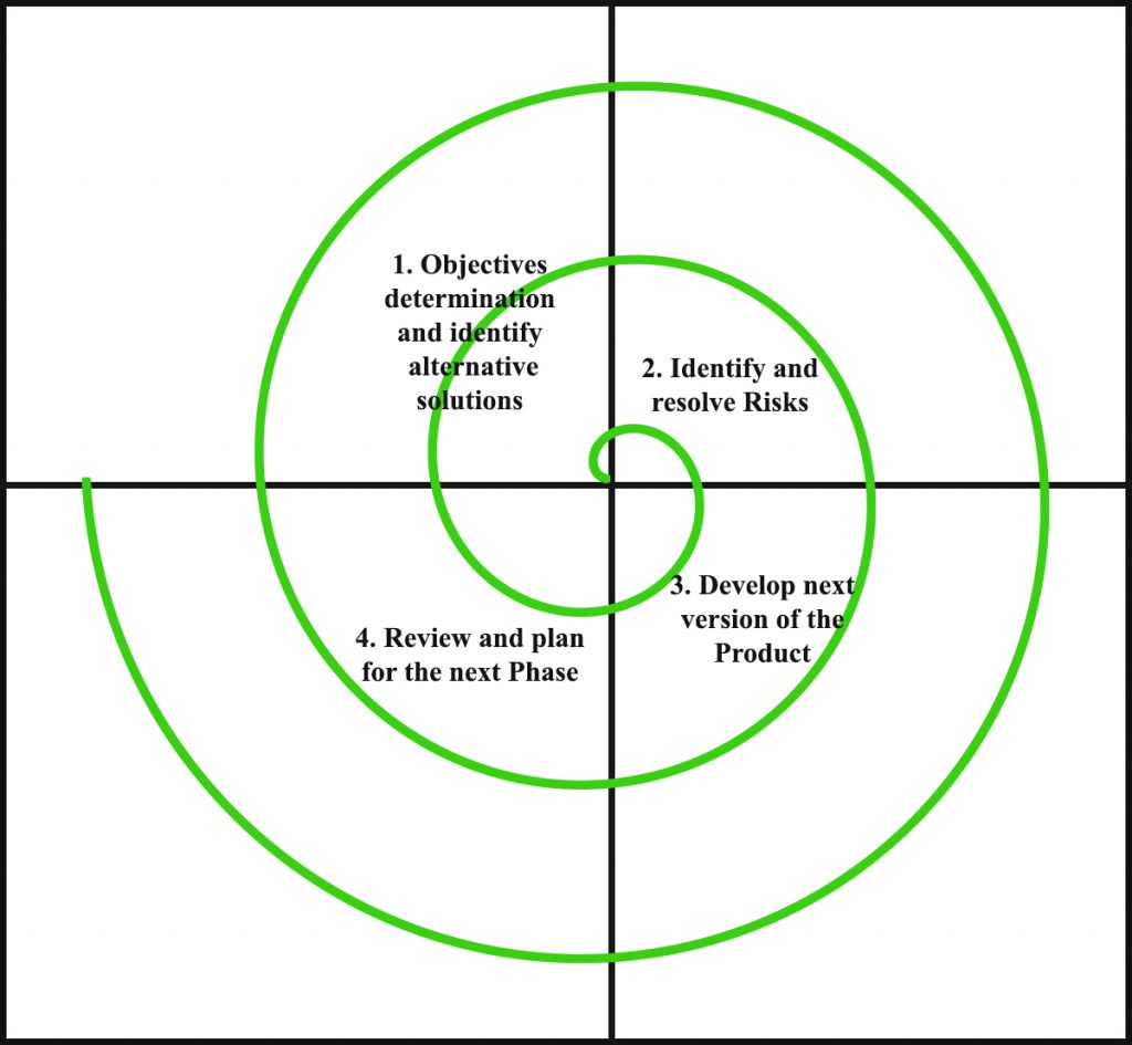
Each phase of Spiral Model is divided into four quadrants as shown in the above figure. The functions of these four quadrants are discussed below-
- Objectives determination and identify alternative solutions: Requirements are gathered from the customers and the objectives are identified, elaborated and analyzed at the start of every phase. Then alternative solutions possible for the phase are proposed in this quadrant.
- Identify and resolve Risks: During the second quadrant all the possible solutions are evaluated to select the best possible solution. Then the risks associated with that solution is identified and the risks are resolved using the best possible strategy. At the end of this quadrant, Prototype is built for the best possible solution.
- Develop next version of the Product: During the third quadrant, the identified features are developed and verified through testing. At the end of the third quadrant, the next version of the software is available.
- Review and plan for the next Phase: In the fourth quadrant, the Customers evaluate the so far developed version of the software. In the end, planning for the next phase is started.
- Risk Handling in Spiral Model
A risk is any adverse situation that might affect the successful completion of a software project. The most important feature of the spiral model is handling these unknown risks after the project has started. Such risk resolutions are easier done by developing a prototype. The spiral model supports coping up with risks by providing the scope to build a prototype at every phase of the software development.
Prototyping Model also support risk handling, but the risks must be identified completely before the start of the development work of the project. But in real life project risk may occur after the development work starts, in that case, we cannot use Prototyping Model. In each phase of the Spiral Model, the features of the product dated and analyzed and the risks at that point of time are identified and are resolved through prototyping. Thus, this model is much more flexible compared to other PDLC models.
2. Why Spiral Model is called Meta Model?
The Spiral model is called as a Meta Model because it subsumes all the other SDLC models. For example, a single loop spiral actually represents the Iterative Waterfall Model. The spiral model incorporates the stepwise approach of the Classical Waterfall Model. The spiral model uses the approach of Prototyping Model by building a prototype at the start of each phase as a risk handling technique. Also, the spiral model can be considered as supporting the evolutionary model – the iterations along the spiral can be considered as evolutionary levels through which the complete system is built.
Advantages of Spiral Model: Below are some of the advantages of the Spiral Model.
- Risk Handling: The projects with many unknown risks that occur as the development proceeds, in that case, Spiral Model is the best development model to follow due to the risk analysis and risk handling at every phase.
- Good for large projects: It is recommended to use the Spiral Model in large and complex projects.
- Flexibility in Requirements: Change requests in the Requirements at later phase can be incorporated accurately by using this model.
- Customer Satisfaction: Customer can see the development of the product at the early phase of the software development and thus, they habituated with the system by using it before completion of the total product.
Disadvantages of Spiral Model: Below are some of the main disadvantages of the spiral model complex:
- The Spiral Model is much more complex than other PDLC models.
- Expensive: Spiral Model is not suitable for small projects as it is expensive.
- Too much dependable on Risk Analysis: The successful completion of the project is very much dependent on Risk Analysis. Without very highly experienced expertise, it is going to be a failure to develop a project using this model.
- Difficulty in time management: As the number of phases is unknown at the start of the project, so time estimation is very difficult.
A. Users
Type of users: End User
B. Functionl And Non-Functional Requirements
- Functional Requirements
Functional requirements for a system describe the functionality or services that the system is expected to provide. Functional Requirements define the fundamental actions that must take place in application in accepting and in processing the inputs and generating the expected outputs. These depend on the type of system being developed and the expected users of the system and the user requirements from the system under development.
a. Data Load: The system provides a user with a graphical interface to Upload Data ,which is used to build Model.
b. Pre-processing: The image uploaded contains unwanted noise etc. they also have a big resolution. Aim of is to make the image suitable for feature extraction.
a. Image Cropping and Image Resolution: Adobe photoshop is used to crop the left and right margins of the image. The size of the image is also reduced, and then the image is converted to PNG format.
b. Removal of Noise
- Gaussian Noise: This is an electronic noise which is caused by thermal vibration of atoms and nature of warm objects.
- Gamma Noise: This is seen in laser based images.
c. Grayscale and Binarization: We created two-valued binary image and convert this image plane into foreground and background pixels can take either 0 or 255 (black or white), an inverted binary function can be created so that pixels are converted to either 0 or 255.
2. Handwriting Features
There are large numbers of features for handwriting of a person. Only seven significant features are extracted, which are popular.
a. Baseline: It is the imaginary line where the writer tends to write. The writer may write above, below or at the middle of the line. It brings out the emotional control of the writer.
b. Letter Size: It determines the size of the letter. It may be tall or short. Average height of word is considered. It tells wether the writer is introvert or extrovert.
c. Line Spacing: It the spacing between two consecutive lines. It gives clues of thinking clarity and the interaction with the environment
d. Word Spacing: The distance that is present between two words. This feature counts the pixels between two words It determines the emotional comfort of a person with other people.
e. Top Margin: It is simply the space left from the top of a page. If the top margin is narrow it shows lack of respect for others, if it is broad it shows modesty and formality.
f. Pen Pressure: It determines whether the user presses more on upstroke or downstroke (light or heavy).If it is heavy it determines strong willed and if it is light it determines sensitive, not strong willed.
g. Slant of Letters: It looks wether the writing is slant to the left or right. It can also be straight. The average slant is right. If left or right it determines goal oriented and sensitive. If it is straight the person might be independent and good decision maker.
3. Non Functional Requirements
a. Performance Requirements: The product should support the end users requirements. The product is capable of processing when the large numbers of files are provided as input and also it must be interactive and the delays involved should be less. So in every action-response of the system, there are no immediate delays.
b. Safety and Security Requirements: The system should be designed in a secured way by applying safety measures. Information transmission should be securely transmitted to nodes without any changes in information. Special exception handling mechanism should be in place to avoid system errors.
c. Software Quality Attribute Availability: The application will not hang and opens quickly and with 99.9% uptime.
d. Reliability: The system should not crash and should identify invalid input and produce suitable error message.
e. Usability: The interface should be intuitive and easily navigable and user friendly.
f. Integrity: The software does not store any cache data or doesn’t use system resources in background.
C. Hardware And Software Requirements
- Hardware Requirements
a. Processor : Intel i5 2.53GHz
b. Hard Disk : 30GB
c. Ram : 4 GB or above
2. Software Requirements
a. Operating system : Windows 8 and above
b. Coding Language : Python
c. Version : 3.7 & above
d. IDE : IDLE
IV. System Design
A. Architecture
Three-tier (layer) is a client-server architecture in which the user interface, business process (business rules) and data storage and data access are developed and maintained as independent modules or most often on separate platforms.
The Architecture of Application is based on three-tier architecture. The three logical tiers are
- Presentation tier - Tkinter
- Middle tier – Python classes
- Data tier
The main reason for considering three-tier architecture for the Application is as follows:
B. Flexibility
- Management of data is independent from the physical storage support,
- Maintenance of the business logic is easier,
- Migration to new graphical environments is faster.
- If there is a minor change in the business logic, we don’t have to install the entire system in individual user’s PCs.
C. Reusability
Reusability of business logic is greater for the presentation layer. As this component is developed and tested, we can use it in any other project and would be helpful for future use.
D. Security
More secured architecture since the client cannot access the database directly.
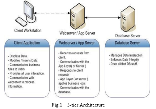
E. Presentation Tier
The presentation tier for the application is python classes’ tkinter is used to take care of the user interaction and the visual part of the project. The various Web forms used by clients are listed below.
F. Middle Tier
The Middle Tier or Business Logic layer consists of python classes.
G. Data Tier
The Data Tier layer consists of database such as the data tier mainly concentrated on manipulating the data using a database management system. Here we implement the data tier using MS Access. Different varieties of data base are Oracle, SQL
V. DETAILED DESIGN
Detailed design starts after the system design phase is completed and the system design has been certified through the review. The goal of this phase is to develop the internal logic of each of the modules identified during system design.
In the system design, the focus is on identifying the modules, whereas during detailed design the focus is on designing the logic for the modules. In other words in system design attention is on what components are needed, while in detailed design how the components can be implemented in the software is the issue. The design activity is often divided into two separate phase system design and detailed design. System design is also called top-level design. At the first level focus is on deciding which modules are needed for the system, the specifications of these modules and how the modules should be interconnected. This is called system design or top level design. In the second level the internal design of the modules or how the specifications of the module can be satisfied is decided. This design level is often called detailed design or logic design.
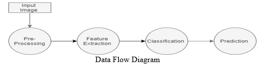
A. Data Flow Diagram
DFD graphically representing the functions, or processes, which capture, manipulate, store, and distribute data between a system and its environment and between components of a system. The visual representation makes it a good communication tool between User and System designer. Structure of DFD allows starting from a broad overview and expand it to a hierarchy of detailed diagrams. DFD has often been used due to the following reasons:
- Logical information flow of the system
- Determination of physical system construction requirements
- Simplicity of notation
- Establishment of manual and automated systems requirements
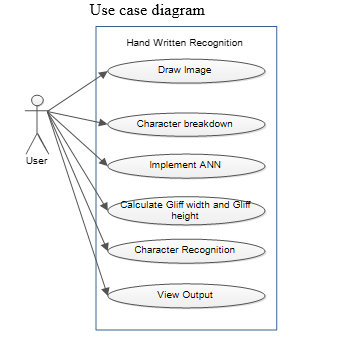
B. Use Case Diagram
Use case diagram is a graph of actors, a set of use cases enclosed by a system boundary, communication associations between the actor and the use case. The use case diagram describes how a system interacts with outside actors; each use case represents a piece of functionality that a system provides to its users. A use case is known as an ellipse containing the name of the use case and an actor is shown as a stick figure with the name of the actor below the figure. The use cases are used during the analysis phase of a project to identify and partition system functionality. They separate the system into actors and use case. Actors represent roles that are played by user of the system. Those users can be humans, other computers, pieces of hardware, or even other software systems.
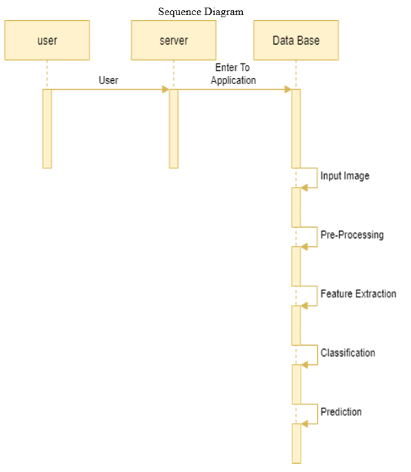
C. Sequence Diagram
A sequence diagram shows object interactions arranged in time sequence. It depicts the objects and classes involved in the scenario and the sequence of messages exchanged between the objects needed to carry out the functionality of the scenario. Sequence diagrams are sometimes called event diagrams, event scenarios.
UML sequence diagrams are used to represent or model the flow of messages, events and actions between the objects or components of a system. Time is represented in the vertical direction showing the sequence of interactions of the header elements, which are displayed horizontally at the top of the diagram Sequence Diagrams are used primarily to design, document and validate the architecture, interfaces and logic of the system by describing the sequence of actions that need to be performed to complete a task or scenario. UML sequence diagrams are useful design tools because they provide a dynamic view of the system behavior.
- Purpose: The sequence diagram is used primarily to show the interactions between objects in the sequential order that those interactions occur. One of the primary uses of sequence diagrams is in the transition from requirements expressed as use cases to the next and more formal level of refinement.
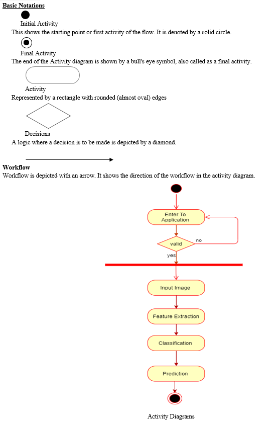
D. Activity Diagrams
Activity diagrams represent the business and operational workflows of a system. An Activity diagram is a dynamic diagram that shows the activity and the event that causes the object to be in the particular state. It is a simple and intuitive illustration of what happens in a workflow, what activities can be done in parallel, and whether there are alternative paths through the workflow.
VI. IMPLEMENTATION
Implementation is the process of converting a new or a revised system design into an operational one. The objective is to put the new or revised system that has been tested into operation while holding costs, risks, and personal irritation to the minimum. A critical aspect of the implementation process is to ensure that there will be no disrupting the functioning of the organization. The best method for gaining control while implanting any new system would be to use well planned test for testing all new programs. Before production files are used to test live data, text files must be created on the old system, copied over to the new system, and used for the initial test of each program.
Another factor to be considered in the implementation phase is the acquisition of the hardware and software. Once the software is developed for the system and testing is carried out, it is then the process of making the newly designed system fully operational and consistent in performance.
Implementation is the most crucial stage in achieving a successful system and giving the user’s confidence that the new system is workable and effective. Implementation of a modified application to replace an existing one. This type of conversation is relatively easy to handle, provide there are no major changes in the system.
A. System Implementation
There are three major types of implementation are there but the following are proposed for the project.
B. Parallel Conversion type of Implementation
In this type of implementation both the current system and the proposed system run in parallel. This happens till the user gets the complete confidence on the proposed system and hence cuts of the current system.
C. Phase - In Method of Implementation
In this type of implementation the proposed system is introduced phase-by-phase. This reduces the risk of uncertainty of proposed system.
Each program is tested individually at the time of development using the data and has verified that this program linked together in the way specified in the programs specification, the computer system and its environment is tested to the satisfaction of the user. The system that has been developed is accepted and proved to be satisfactory for the user. And so the system is going to be implemented very soon. A simple operating procedure is included so that the user can understand the different functions clearly and quickly.
Initially as a first step the executable form of the application is to be created and loaded in the common server machine which is accessible to the entire user and the server is to be connected to a network. The final stage is to document the entire system which provides components and the operating procedures of the system.
Implementation is the stage of the project when the theoretical design is turned out into a working system. Thus it can be considered to be the most critical stage in achieving a successful new system and in giving the user, confidence that the new system will work and be effective. The implementation stage involves careful planning, investigation of the existing system and it’s constraints on implementation, designing of methods to achieve changeover and evaluation of changeover methods.
Implementation is the process of converting a new system design into operation. It is the phase that focuses on user training, site preparation and file conversion for installing a candidate system. The important factor that should be considered here is that the conversion should not disrupt the functioning of the organization.
D. Implementation Methodology of the Project
The project is implemented in modular approach. Each module is coded as per the requirements and tested and this process is iterated till the all the modules have been thoroughly implemented.
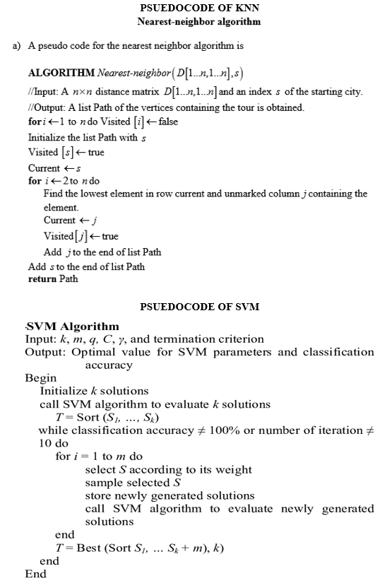
E. Algorithms used in Project KNN
K-nearest neighbours (KNN) algorithm is a type of supervised ML algorithm which can be used for both classification as well as regression predictive problems. However, it is mainly used for classification predictive problems in industry.
K-nearest neighbours (KNN) algorithm uses ‘feature similarity’ to predict the values of new data points which further means that the new data point will be assigned a value based on how closely it matches the points in the training set. We can understand its working with the help of following steps −
Step 1 − For implementing any algorithm, we need dataset. So during the first step of KNN, we must load the training data from the heart disease patients datalist and test data from the new patient entry info currently being taking tests.
Test data set – collected data samples.
Train data set – UCI & real time data from hospital.
Step 2 − Next, we need to choose the value of K i.e. the nearest data points. K can be any integer.
Here k is taken from test data set, which acts like a centroid point.
Step 3 − For each point in the test data do the following −
- 3.1 − Calculate the distance between test data and each row of training data with the help of any of the method namely: Euclidean, Manhattan or Hamming distance. The most commonly used method to calculate distance is Euclidean.
- 3.2 − Now, based on the distance value, sort the patients data based on parameters like age, gender, alcohol, bp, smoking parameters as preference of data in ascending order.
- 3.3 − Next, it will choose the top K rows from the sorted array.
- 3.4 − Now, it will assign a class to the test point based on most frequent segments from the patient data of these rows.
Step 4 – End
In our project we compare k value with train data set using KNN methodology likes Euclidean, Manhattan, where we cluster the values based on the nearest distance. Here we get nearest matches of heart disease preference to test data from train data set in turn we predict the content values from it.
F. Support Vector Machine (SVM) is a supervised machine learning algorithm which can be used for both classification or regression challenges. However, it is mostly used in classification problems. In the SVM algorithm, we plot each data item as a point in n-dimensional space (where n is number of features you have) with the value of each feature being the value of a particular coordinate. Then, we perform classification by finding the hyper-plane that differentiates the two classes very well .
- Identify the right hyper-plane (Scenario-1): Here, we have three hyper-planes (A, B and C). Now, identify the right hyper-plane to classify star and circle. You need to remember a thumb rule to identify the right hyper-plane: “Select the hyper-plane which segregates the two classes better”. In this scenario, hyper-plane “B” has excellently performed this job.
- Identify the right hyper-plane (Scenario-2): Here, we have three hyper-planes (A, B and C) and all are segregating the classes well. Now, How can we identify the right hyper-plane?Here, maximizing the distances between nearest data point (either class) and hyper-plane will help us to decide the right hyper-plane. This distance is called as Margin. Let’s look at the below snapshot:
Above, you can see that the margin for hyper-plane C is high as compared to both A and B. Hence, we name the right hyper-plane as C. Another lightning reason for selecting the hyper-plane with higher margin is robustness. If we select a hyper-plane having low margin then there is high chance of miss-classification.
3. Identify the right hyper-plane (Scenario-3): Hint: Use the rules as discussed in previous section to identify the right hyper-plane Some of you may have selected the hyper-plane B as it has higher margin compared to A. But, here is the catch, SVM selects the hyper-plane which classifies the classes accurately prior to maximizing margin. Here, hyper-plane B has a classification error and A has classified all correctly. Therefore, the right hyper-plane is A.
4. Can we classify two classes (Scenario-4)?: Below, I am unable to segregate the two classes using a straight line, as one of the stars lies in the territory of other(circle) class as an outlier. As I have already mentioned, one star at other end is like an outlier for star class. The SVM algorithm has a feature to ignore outliers and find the hyper-plane that has the maximum margin. Hence, we can say, SVM classification is robust to outliers.
5. Find the hyper-plane to segregate to classes (Scenario-5): In the scenario below, we can’t have linear hyper-plane between the two classes, so how does SVM classify these two classes? Till now, we have only looked at the linear hyper-plane. SVM can solve this problem. Easily! It solves this problem by introducing additional feature. Here, we will add a new feature z=x^2+y^2. Now, let’s plot the data points on axis x and z:
In above plot, points to consider are:
- All values for z would be positive always because z is the squared sum of both x and
- In the original plot, red circles appear close to the origin of x and y axes, leading to lower value of z and star relatively away from the origin result to higher value of z.
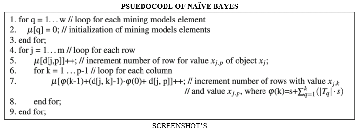
G. NAÏVE BAYES
It is a classification technique based on Bayes’ Theorem with an assumption of independence among predictors. In simple terms, a Naive Bayes classifier assumes that the presence of a particular feature in a class is unrelated to the presence of any other feature.
For example, a fruit may be considered to be an apple if it is red, round, and about 3 inches in diameter. Even if these features depend on each other or upon the existence of the other features, all of these properties independently contribute to the probability that this fruit is an apple and that is why it is known as ‘Naive’.
Naive Bayes model is easy to build and particularly useful for very large data sets. Along with simplicity, Naive Bayes is known to outperform even highly sophisticated classification methods.
VII. SOFTWARE TESTING
Testing is the major process involved in software qualityassurance (QA). It is iterative process. Here test data is prepared and is used to test the modules individually. System testing makes sure that all components of the system function properly as a unit by actually forcing the system to fail.
The test causes should be planned before testing begins. Then as the testing progresses, testing shifts focus in an attempt to find errors in integrated clusters of modules and in the entire system. The philosophy behind testing is to find errors. Actually testing is the estate of implementation that is aimed at ensuring that the system works actually and efficiently before implementation.
Testing is done for each module. After testing all the modules, the modules are integrated and testing of the final system is done with the test data, specially designed to show that the system will operate successfully in all its aspects conditions. The procedure level testing is made first. By giving improper inputs, the errors occurred are noted and eliminated. Thus the system testing is a confirmation that all is correct and an opportunity to show the user that the system works. The final step involves Validation testing, which determines whether the software function as the user expected. The end-user rather than the system developer conduct this test most software developers as a process called “Alpha and Beta test” to uncover that only the end user seems able to find.
This is the final step in system life cycle. Here we implement the tested error-free system into real-life environment and make necessary changes, which runs in an online fashion. Here system maintenance is done every months or year based on company policies, and is checked for errors like runtime errors, long run errors and other maintenances like table verification and reports.
During the requirement analysis and design, the output is a document that is usually textual and non-executable. After the coding phase, computer programs are available that can be executed for testing purpose. This implies that testing not only has to uncover errors introduced during coding, but also errors introduced during the previous phases.
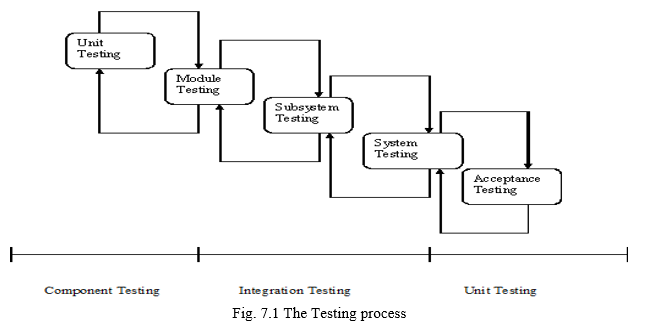
The various types of testing done on the system are:
- Unit Testing
- Integration Testing
- Validation Testing
- System Testing
- Acceptance Testing
A. Unit Testing
Unit testing verification efforts on the smallest unit of software design, module. This is known as “Module Testing”. The modules are tested separately. This testing is carried out during programming stage itself. In these testing steps, each module is found to be working satisfactorily as regard to the expected output from the module.
B. Integration Testing
Integration testing is a systematic technique for constructing tests to uncover error associated within the interface. In the project, all the modules are combined and then the entire programmer is tested as a whole. In the integration-testing step, all the error uncovered is corrected for the next testing steps.
C. Validation Testing
To uncover functional errors, that is, to check whether functional characteristics confirm to specification or not specified.
D. System Testing
Once individual module testing completed, modules are assembled to perform as a system. Then the top down testing, which begins from upper level to lower level module testing, has to be done to check whether the entire system is performing satisfactorily.
After unit and integration testing are over then the system as whole is tested. There are two general strategies for system testing.
They are:
- Code Testing: This strategy examines the logic of the program. A path is a specific combination of conditions handled by the program. Using this strategy, every path through the program is tested.
- Specification Testing: This strategy examines the specifications stating what the program should do and how it should perform under various conditions. The test cases are developed for each condition of developed system and processed. It is found that the system developed perform according to its specified requirements. The system is used experimentally to ensure that the software will run according to tits specification and in the way user expect. Specification Testing is done successfully by entering various types of end data. It is checked for both valid and invalid data and found System is working properly as per requirement.
E. Acceptance Testing
When the system has no measure problem with its accuracy, the system passes through a final acceptance test. This test confirms that the system needs the original goal, Objective and requirements established during analysis. If the system fulfils all the requirements, it is finally acceptable and ready for operation.
F. Plan
A software project test plan is a document that describes the objectives, scope approach and focus of a software testing effort. This process of preparing a test plan is a useful way to think through the efforts needed to validate the acceptability of a software product. The completed document will help the people outside the test group understand ‘Why and How’ of production validation. Different test plans are used at different levels of testing.
- Test Plans used in Unit Testing: Each module is tested for correctness whether it is meeting all the expected results.Condition loops in the code are properly terminated so that they don’t enter into an infinite loop. Proper validations are done so as to avoid any errors related to data entry from user.
VIII. FUTURE ENHANCEMENTS
The future work can be to include more features from the micro approach of handwriting
analysis like the loops of alphabet 'f' and 'l', gradient, concavity of letters and so on in order to predict more accurate results.
Conclusion
This paper carries out a study of various feature based classification techniques for offline handwritten character recognition. After experimentation, it proposes an optimal character recognition technique. The proposed method involves segmentation of a handwritten word by using heuristics and artificial intelligence. Three combinations of Fourier descriptors are used in parallel as feature vectors. Support vector machine is used as the classifier. Post processing is carried out by employing lexicon to verify the validity of the predicted word. The results obtained by using the proposed Character Recognition system are found to be satisfactory.
References
[1] H. Zeng,(2020)An Off-line Handwriting Recognition Employing Tensorflow. International Conference on Big Data, Artificial Intelligence and Internet of Things Engineering (ICBAIE). [2] A. Beltrán and S. Mendoza, “Efficient algorithm for real-time handwritten character recognition in mobile devices “,2011, 8th International Conference on Electrical Engineering, Computing Science and Automatic Control, 2011, pp. 1-6, doi: 10.1109/ICEEE.2011.6106583. [3] H. A. Shiddieqy, T. Adiono and I. Syafalni, \"Mobile Client-Server Approach for Handwriting Digit Recognition\'\',2019 International Symposium on Electronics and Smart Devices (ISESD), 2019, pp. 1-4, doi: 10.1109/ISESD.2019.8909448. [4] R. Vaidya, D. Trivedi, S. Satra and P. M. Pimpale, \"Handwritten Character Recognition Using DeepLearning\",2018 Second International Conference on Inventive Communication and Computational Technologies (ICICCT), 2018, pp. 772-775, doi: 10.1109/ICICCT.2018.8473291. [5] H. Du, P. Li, H. Zhou, W. Gong, G. Luo and P. Yang, \"WordRecorder: Accurate Acoustic-based Handwriting Recognition Using Deep Learning,\"IEEE INFOCOM 2018 - IEEE Conference on Computer Communications, 2018, pp. 1448-1456, doi: 10.1109/INFOCOM.2018.8486285. Fig - 7: Image capturing Fig -8: Printed text output © 2021, IRJET | Impact Factor value: 7.529 [6] Kavitha, D., & Shamini, P. (2016),\"Handwritten Document into Digitized Text Using Segmentation Algorithm\", An International Journal of Advanced Computer Technology. Retrieved from https://ijact.in/index.php/ijact/article/view/465 [7] Chammas, C. Mokbel, R. Al Hajj Mohamad, C. Oprean, L. L. Sulem and G. Chollet, \"Reducing language barriers for tourists using handwriting recognition enabled mobile application,\"2012 2nd International Conference on Advances in Computational Tools for Engineering Applications (ACTEA), 2012, pp. 20-23, doi: 10.1109/ICTEA.2012.6462868 [8] S. B. K.S., V. Bhat and A. S. Krishnan, \"SolveIt: An Application for Automated Recognition and Processing of Handwritten Mathematical Equations, \"2018 4th International Conference for Convergence in Technology (I2CT), 2018, pp. 1-8, doi: 10.1109/I2CT42659.2018.9058273. [9] T. Mantoro, A. M. Sobri and W. Usino, \"Optical Character Recognition (OCR) Performance in ServerBased Mobile Environment,\"2013 International Conference on Advanced Computer Science Applications and Technologies, 2013, pp. 423-428, doi: 10.1109/ACSAT.2013.89. [10] V. V. Mainkar, J. A. Katkar, A. B. Upade and P. R. Pednekar, \"Handwritten Character Recognition to Obtain Editable Text,\" 2020 International Conference on Electronics and Sustainable Communication Systems (ICESC), 2020, pp. 599-602, doi: 10.1109/ICESC48915.2020.9155786.
Copyright
Copyright © 2022 Saniya Firdous. This is an open access article distributed under the Creative Commons Attribution License, which permits unrestricted use, distribution, and reproduction in any medium, provided the original work is properly cited.

Download Paper
Paper Id : IJRASET42114
Publish Date : 2022-05-01
ISSN : 2321-9653
Publisher Name : IJRASET
DOI Link : Click Here
 Submit Paper Online