

Ijraset Journal For Research in Applied Science and Engineering Technology
Experimentation Investigation of Hard facing Layer by MMAW on Alloy Steel
Authors: Pooja Rani, Dr. Dinesh Kumar, Er. Tarun Anand
DOI Link: https://doi.org/10.22214/ijraset.2022.39840
Certificate: View Certificate
Abstract
The wearing of metal parts might be defined as a gradual decay or breakdown of the metal. When a part becomes so deformed that it cannot perform adequately, it must be replaced or rebuilt. While the end results of wear are similar, the causes of wear are different. It is essential to understand the wear factors involved before making a hard surfacing product selection. It would be easy to select a surfacing alloy if all metal components were subjected to only one type of wear. However, a metal part is usually worn by combinations of two or more types of wear. This makes an alloy selection considerably more complicated. A hard surfacing alloy should be chosen as a compromise between each wear factor. The initial focus should centre on the primary wear factor and then the secondary wear factor(s) should be examined. For example: upon examining a worn metal part, it is determined that the primary wear factor is abrasion and the secondary wear factor is light impact. The surfacing alloy chosen should have very good abrasion resistance but also have a fair amount of impact resistance.
Introduction
I. INTRODUCTION
Welding is a process of permanent joining of two materials (usually metals) through localized coalescence resulting from a suitable combination of temperature, pressure and metallurgical conditions. Depending upon the combination of temperature and pressure from a high temperature with no pressure to a high pressure with low temperature, a wide range of welding processes has been developed. While there are many methods for joining metals, welding is one of the most convenient and rapid methods available. The term welding refers to the process of joining metals by heating them to their melting temperature and causing the molten metal to flow together. These range from simple steel brackets to nuclear reactors. Welding, like any skilled trade, is broad in scope and one cannot become a welder simply by reading a book. One need practice and experience as well as patience; however, much can be gained through study. For instance, by learning the correct method or procedure for accomplishing a job from a book, you may eliminate many mistakes that otherwise would occur through trial and error. Welding is not new. The earliest known form of welding, called forge welding, dates back to the year 2000 B.C. Forge welding is a primitive process of joining metals by heating and hammering until the metals are fused (mixed) together. Although forge welding still exists, it is mainly limited to the blacksmith trade.
Welding is the joining of metals. What welding does is join metals or other materials at their molecular level with the technology we have at the moment. Welding technology is always changing, and with so many military forces relying on it to make their defense products, there are welding processes we are yet to hear about. What we know about modern welding is that there are four components to a weld. The four components are the metals themselves, a heat source, filler material, and some kind of shield from the air. The welding process works like this. The metal gets heated to its melting point, at the same time there is some sort of shielding from the air to protecting it, and then a filler metal is added to the area that needs to be joined ultimately producing a single piece of metal.
II. MANUAL METAL ARC WELDING PROCESS
In this process an arc is drawn between a coated consumable electrode and the work piece. The metallic core-wire is melted by the arc and is transferred to the weld pool as molten drops. The electrode coating also melts to form a gas shield around the arc and the weld pool as well as slag on the surface of the weld pool, thus protecting the cooling weld pool from the atmosphere. The slag must be removed after each layer. Manual Metal Arc welding is still a widely used hardfacing process. Due to the low cost of the equipment, the low operating costs of the process and the ease of transporting the equipment, this flexible process is ideally suited to repair work. In this zone, the falling droplets become "diluted" with molten metal from the base plate. The high temperature and the large convective forces in this region lead to intimate mixing of the molten metal and result in vigorous chemical reactions at the slag-metal interface near the arc.
Shielded metal arc welding (SMAW), also known as manual metal arc (MMA) welding or informally as stick welding, is a manual arc welding process that uses a consumable electrode coated in flux to lay the weld. An electric current, in the form of either alternating current or direct current from a welding power supply, is used to form an electric arc between the electrode and the metals to be joined. In this zone, the falling droplets become "diluted" with molten metal from the base plate. The high temperature and the large convective forces in this region lead to intimate mixing of the molten metal and result in vigorous chemical reactions at the slag-metal interface near the arc. As the weld is laid, the flux coating of the electrode disintegrates, giving off vapours that serve as a shielding gas and providing a layer of slag, both of which protect the weld area from atmospheric contamination.
III. DESCRIPTION OF PROPOSED WORK
The hardfacing methodology depends upon no of factors such as: Type of base metal, Thickness required, Size, Weight and shape of parts, Volume of parts and Area of hardfacing etc. The usual methodology of the hardfacing would consist of the following steps:
- Sample and surface preparation: The sample of suitable dimension is to be taken and surface preparation for hardfacing consists of cleaning the affected area and usually providing a machined.
- Griping of the specimen: Suitable arrangement for fixing of specimen would be devised.
- Deposition of hardfacing material on the specimen surface using FCAW Welding.
- Micro-hardness along the X-section of weldment will be evaluated by using the micro-hardness test to check the uniformity in the structure.
- Micro-structure will be analyzed for uniformity of the structure by using the optical microscopy test.
- Wear test of specimen at different areas.
- Chemical Composition of Base Metal and Electrode The composition of base metal and welding electrode was found by using spectrometer (AAS). The following Table 4.1 shows chemical composition of base metal (En-31 steel). Table 4.2 and 4.3 shows the chemical composition of electrodes
- Fixed Parameters The following are the parameters that were kept constant throughout the experiments Total dimensions of specimen: 200x50x5mm
- Welding parameters: Current (130 amp), Voltage (30 V), Welding speed (3.8 mm/s), Power supply (AC).
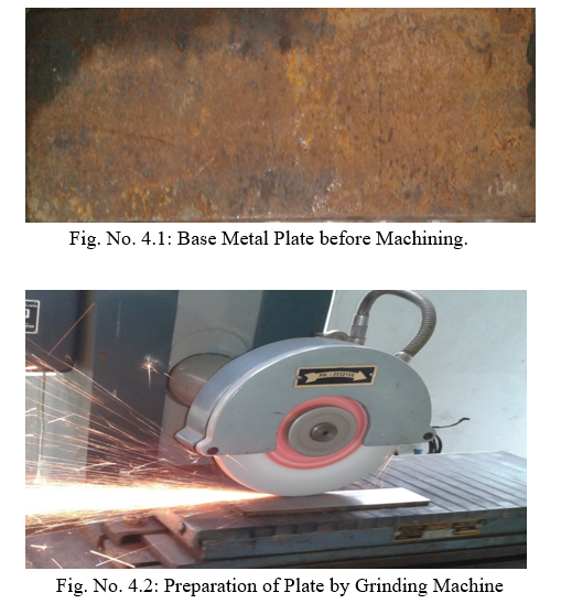
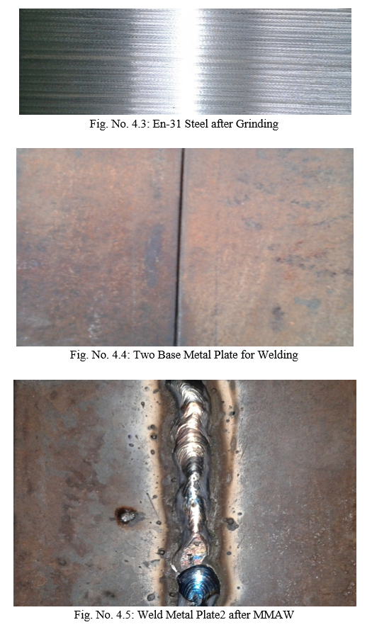
- Specimen Preparation Alloy carbon steel (En-31) plate was machined on grinding machine to make specimen for proper testing. The machined plates were then cleaned with acetone to remove impurities from the surface to make the specimen ready for welding (Fig. 4.1 and 4.3).
Facing is the process of depositing, by one of various welding techniques, a layer or layers of metal of specific properties on certain areas of metal parts that are exposed to wear. By expanding this definition a little further, it can be seen that hardfacing has more to offer than most other wear prevention treatments:
Following are the some of the hard facing electrodes with their designations:
- ROYAL – CI: A medium heavy coated rutile type hard facing electrodes It deposits a tough air hardening type of weld metal approximately 250 BHN hardness. The weld metal is machinable and recommended for hard surfacing on hard base material.
- Application: Suitable for gears, shafts, axles, hammers, pinion teeth, pulleys, couplings, spindle.
2. ROYAL – CII: A medium heavy coated rutile type good running hard facing electrode, deposit a tough air hardening type of weld metal of approximately 350 BUN hardness. The weld metal is machinable and recommended for application involving maximum hardness as required.
- Application: Suitable for shears blades and croppers, bamboo chipper knives, coupling conveyer parts, roller, tractor wheels steel casting, shafts.
3. .ROYAL - C III: With a medium heavy coated rutile type electrode, in air hardening type of weld metal where approximately 600 Brinell hardness can be achieved. Weld is non machine able and finished by grinding. The electrode is recommended for hard facing applications on mild steel, carbon steels & low alloy steels where severe conditions of abrasion, friction, accompanied by moderate impact exist. Suitable for couplings, conveyor buckets, shears blades, steel castings, etc.
- Application: Mine rails & crane wheels, hot & cold punching dies, metal cutting & forming tools, crush hammers & caterpillars treads, drilling bits, crane wheels, conveyor buckets, oil expellers, shears & croppers.
4. AFROX-300: Afrox 300 is a basic coated, AC/DC all-position electrode depositing a tough chromium alloy weld metal with a hardness of 250-300 HV (up to 30 HRc). The weld metal may be hardened to above 480 HV (48 HRc) by heating to 900°C and quenching in oil. The weld deposit is capable of withstanding moderate rolling loads, mild abrasion and frictional loading with good resistance to impact.
- Application: Afrox 300 is suitable for rebuilding worn steel or low alloy machine parts, which require machining after welding. It can also be used as a buffer layer between base material and harder overlays. Typical components to be welded with this electrode include shafts, mine car wheels, track links, dragline chains, worn rail ends, tractor rails, drive sprockets, etc. Afrox 300 may be multi-layered.
5. AFROX 452: It is a basic coated AC/DC all-position electrode depositing a weld containing chromium, nickel and molybdenum. The weld metal, which comprises metallic carbides in a martensitic matrix, has a hardness of 420-480 HV (43-48 HRC). The weld metal provides good resistance to abrasion and impact under rolling and to impact loads in wet and dry conditions.
- Application: This versatile electrode is suitable for use in applications where frictional loads and metal-to-metal wear conditions occur. The weld metal is extremely resistant to breakout or spilling, which makes it eminently suitable to use on permanent way crossings, rail ends, excavator bucket lips, tractor drive sprockets and track links, crane drive wheels, etc. The deposit, which is machinable with carbide-tipped tools, is also suitable for use as a low cost buffer layer for the deposition of high alloy wear resistant deposits.
IV. RESULTS & DISCUSSIONS
A. Micro Hardness Measurements
Hardness is the ability of the metal to resist penetration, abrasion wear or the absorption energy under impact load. Hardness measurement provides the information about the metallurgical changes caused by welding. The hardness tests were carried out using Vickers micro hardness tester at 300 gm constant load for all the specimens in order to analyze the above mentioned properties of the welds.
Table No. 4.1: Micro Hardness Test Results (MVH) for Weld Plate 2
|
Sr. No. |
Hardness Value (VHN) |
|
En-31 steel |
268 |
|
2 Layer |
210 |
|
3 Layer |
223 |
|
HAZ (2 Layer) |
454 |
|
HAZ (3 Layer) |
382 |
B. Discussion of Micro Hardness Test for Weld Plate-2
It is clear from Fig. 5.1 that micro hardness values are increasing uniformly. It can be seen that the hardness level increases as location were changed. Hardness of parent metal was reduced when 3 layer of weld bead were acted and hardness was increased uniformly at HAZ (Heat Affected Zone) for 2 layers and as layers were increased hardness was decreased at HAZ. The maximum micro hardness on HAZ weld centre is observed for weld plate-2 using S.S electrode E304.
Table No. 4.2: Micro Hardness Test Results (MVH) for Weld Plate-3
|
Sr. No. |
Hardness Value (VHN) |
|
En-31 steel |
271 |
|
2 Layer |
219 |
|
3 Layer |
223 |
|
HAZ (2 Layer) |
460 |
|
HAZ (3 Layer) |
471 |
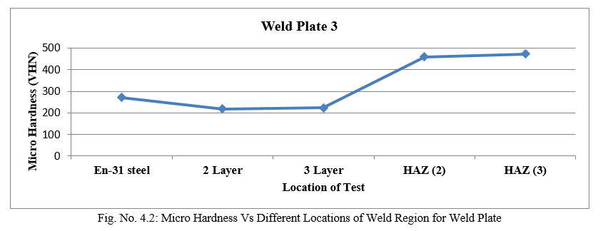
C. Discussion of Micro Hardness Test for Weld Plate-3
It is clear from Fig. 5.2 that micro hardness values are increasing uniformly. It can be seen that the hardness level increases as location were changed. Hardness of parent metal was reduced when 2-3 layer of weld bead were acted and hardness was increased uniformly at HAZ (Heat Affected Zone) for 2 layers and as layers were increased hardness was also increased at HAZ. The maximum micro hardness on HAZ for 3 layers is observed for weld plate-3 using S.S electrode E304.
D. Wear Test Analysis
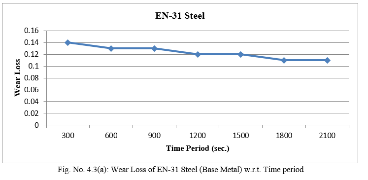
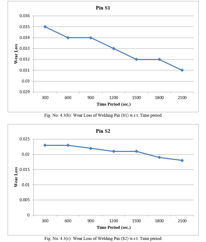
The organization for Economic Cooperation and Development (OECD) defined wear as: “The progressive loss of substance from the operating surface of a body occurring as result of relative motion at the surface”. Also it is damage to a surface as a result of relative motion with respect to another surface under load in dry conditions. The wear tests were conducted in normal atmospheric conditions. Before the wear test, all the specimens taken for analysis were cleaned with acetone and the weighed using a digital electronic balance with an accuracy of ±0.1 mg. Specimens were in the form of cylindrical pin of 4 mm dia. and 30 mm length was used. The wear test was carried out at 800 rpm with an applied load of 70 kg for 5 to 35 minutes duration as shown in Table 5.3. During sliding, the load was applied on the specimen through cantilever mechanism and the specimens brought in intimate contact with the rotating disc at a track radius of 100 mm. After completion of wear test, the specimen was removed, cleaned by acetone and dried at room temperature, then weighed to measure the weight loss and expressed in terms of volume loss per unit sliding distance. Table 5.3 shows the experimental results of wear tests conducted on all the specimens.
Table 4.4 Data of Wear Loss of Welding Sample (pins)
|
Time period (sec)
|
Wear loss of B1 Base Metal |
Wear loss of S1 |
Wear loss of S2 |
|
300 |
0.14 |
0.035 |
0.023 |
|
600 |
0.13 |
0.034 |
0.023 |
|
900 |
0.13 |
0.034 |
0.022 |
|
1200 |
0.12 |
0.033 |
0.021 |
|
1500 |
0.12 |
0.032 |
0.021 |
|
1800 |
0.11 |
0.032 |
0.019 |
|
2100 |
0.11 |
0.031 |
0.018 |
B1=Base Metal Pin
S1=Welding Specimen Pin1 for Weld Plate2
S2=Welding Specimen Pin2 for weld Plate3
E. Discussion of Wear Test
The graphs were plotted for percentage of wear loss with respect to time period. The result shows that (Fig. 4.3(a)) the wear loss for 300 sec time period was maximum and continuously goes on decreasing with increase in time as the percentage of Cr (1.172%). Wear loss has been decreased by addition of Cr (18.5%) as compared to base metal (Fig. 4.3(b)). After 900 seconds the wear loss becomes constant (Fig. 4.3 (c)). All the specimens have nearly same trend (decreasing) of wear loss. From Fig. 4.3 (a-c), it can be seen that wear loss is continuously goes on decreasing with time and with increase of percentage of chromium. This all is because of Cr which is wear resistant substance.
F. Microstructure Test of Specimens
The welded specimens were prepared metallographically by conventional grinding and polishing. The polished and etched surfaces were examined using an optical microscope and digital micrographs were taken as shown in Fig. 4.4 & Fig. 4.5
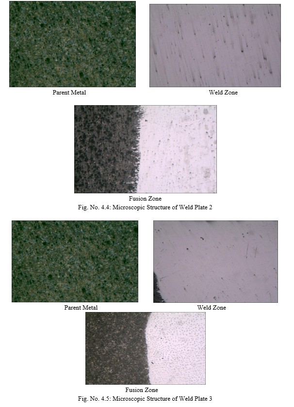
G. Discussion of Microstructure
The micrograph of the Fig.5.4 and Fig. 5.5 reveals that there was presence of austenitic microstructure of parent Metal (EN-31 Steel) which is annealed structured. From Fig. 5.4 parent metal was annealed structure of EN-31 steel, Weld metal (S S-304) was austenitic stainless steel which was not etchable with natal. Because after etching with natal of 3%, the whole structure was dark black. The fusion zone shows that there was a proper fusion of weld metal with parent metal. The density of flow lines that banding and morphology of austenite has been found to vary in specimens. Dark region is not acicular. The light colored region of the microstructure is the ferrite. The pearlite has a very fine structure, which makes the steel very hard. Unfortunately this also makes the steel quite brittle and much less ductile then mild steel. There was a deformation of the specimen and the grains in the microstructure fail by void formation as the metal flows around hard particles in the microstructure. This is also known as micro void coalescence. Voids as a dimple can be seen in under high magnification. This absorbs a lot of energy and toughness is high. Conclusions
Conclusion
The Three types of base metal on the basis of their design and two types of electrode on the basis their chemical composition were selected to conduct the experiment. On the basis of result following conclusion were made: As Cr increased, the wear resistance in the weld has increased in specimen no. 3, which was hardfaced using modified electrode. As a result of increase in Cr from 16.5 % to 18.5 % the hardness increases due to the formation of chromium carbide at the grain boundary MMAW indicate better result on EN-31 steel as compared to the base metal without Due to increase in Cr value, there was also a progressive refinement in the grains of the welded layers, this has been observed from the microstructure photographs In addition to the present work further work can be done in following directions: Compounds and their percentages can be varied to see the effect of variation on wear behavior and Chromium can be replaced by other hard facing alloys Vanadium, Molybdenum, Boron, Titanium etc. Post weld heat treatment can be done to improve grain refinement
References
[1] Kumar S., Mondal D.P., Khaira H.K. and Jha A.K., (1999) “Improvement in High Stress Abrasive Wear Property of Steel by hardfacing”, 711-715 [2] Aoh J. N., Chen J., (2001) “On the wear characteristics of cobalt-based hardfacing layer after thermal fatigue and oxidation”. J of Wear, Vol. 250, 611–620. [3] Amushahi, M.H., F. Ashrafizadeh, M. Shamani, (2010) “Characterization of boride-rich hardfacing on carbon steel by arc spray and GMAW processes”. Surface and Coatings Technology, Volume 204, Issues 16–17, 15 May 2010, Pages 2723-2728. [4] Balasubramanian V., Varahamoorthy R., Ramachandran C.S. and Muralidharan C., (2009) “Selection of welding process for hardfacing on carbon steels based on quantitative and qualitative factors”, V 40, 887–897. [5] Buchanan V.E., Shipway P.H., McCartney D.G., (2007) “Microstructure and abrasive wear behaviour of shielded metal arc welding hardfacings used in the sugarcane industry”. J of Wear, Vol. 263, 99–110. [6] Buchely M.F., Gutierrez J.C., Leon L.M., Toro A., (2005) “The effect of microstructure on abrasive wear of hardfacing alloys”, V 259, 52–61. [7] Celaya F. O., Pech-Canul M.I., Lopez-Cuevas J., Rendongeles J.C., Pech-Canul M.A., (2007) “Microstructure and impact behavior of Al/SiCo composites fabricated by pressureless infiltration with different types of SiCo”. Journal of Materials Processing Technology, Vol. 183, 368–373. [8] Chen B., Chai C.,Peng J., (2003) “A High-Fe Aluminum matrix welding filler metal for hardfacing aluminum-silicon alloys”. Journal of Wuhan University of Technology – Material Science. [9] Choteborsky R., Hrabe P., Muller M., Savkova J., Jirka M., (2008) “Abrasive wear of high chromium Fe-Cr-C hardfacing alloys”. V 54, 192–198. [10] Coronado J.J., Caicedo Holman F., Gomez Adolfo L., (2009) “The effects of welding processes on abrasive wear resistance for hardfacing deposits”, V 42, 745–749. [11] KenchiReddy K.M., Jayadeva C.T., (2012), “Experimental Study on the Effect of Microstructure on Wear Behavior of Fe-Cr-C Hardfacing Alloys”. Bonfring International Journal of Industrial Engineering and Management Science, Vol. 2, No. 1, 6-9. [12] Kiran V. T. B., Krishna M., Natraj J. R., Kumar S., (2012) “Development and Characterization of an Electrode Deposition Procedure for Crack-Free Hardfacing of Low Carbon Steel”. International Journal of Engineering and Technology, Vol-4, 18-25.” [13] Lee K., Lee S., Kim Y., Hong H., Oh Y., Kim S.,(2003) “The effects of additive elements on the sliding wear behavior of Fe-base hardfacing alloys”. J of Wear, Vol. 255, 481–488. [14] Pradeep G, Ramesh P.D., (2010) “A review paper on hardfacing processes and materials”. V 2, 6507-6510. [15] Wang X.H., Zou Z.D., Qu S.Y., Song S.L., (2005). “Microstructure and wear properties of Fe-based hardfacing coating reinforced by TiC particles”. Journal of Materials Processing Technology, vol. 168, 89–94.
Copyright
Copyright © 2022 Pooja Rani, Dr. Dinesh Kumar, Er. Tarun Anand. This is an open access article distributed under the Creative Commons Attribution License, which permits unrestricted use, distribution, and reproduction in any medium, provided the original work is properly cited.

Download Paper
Paper Id : IJRASET39840
Publish Date : 2022-01-07
ISSN : 2321-9653
Publisher Name : IJRASET
DOI Link : Click Here
 Submit Paper Online