

Ijraset Journal For Research in Applied Science and Engineering Technology
High Efficiency Anisotropic Metamaterial Reflector for Cross Polarization Conversion
Authors: Engr. Muhammad Asif Ramzan, Umair Iftikhar Tauni, Mudassir Murtaza, Dr. Shahzada Alamgir Khan
DOI Link: https://doi.org/10.22214/ijraset.2025.68969
Certificate: View Certificate
Abstract
Polarization control plays a significant role in various scientific and engineering applications such as communication, optical sensing, and molecular biology. However, traditional methods like the Faraday Effect and Birefringence are limited by narrow bandwidths and large sizes. This paper is presenting the design of a broadband, high-efficiency anisotropic metasurface reflector for cross-polarization conversion, addressing these limitations. The metasurface, composed of square split-ring resonators, demonstrates an exceptional polarization conversion ratio (PCR) exceeding 95% for linearly polarized incident waves in the range frequency of 8-20 GHz. The suggested metasurface attains almost 100% conversion of cross-polarization at the resonance frequencies (9.30 GHz, 13.69 GHz, and 18.48 GHz), according to experimental results. This metasurface works very well for broadband applications that need to control polarization precisely.
Introduction
I. INTRODUCTION
Polarisation refers to orientation of electric field of an electromagnetic wave with respect to magnetic field while the wave travels along the direction. It is one of the essential parameters of EM waves and is majorly involved in various contemporary technologies such as communication systems, imaging systems and sensors. Transverse waves on the other hand are defined by the direction of vibration of the electric field as regards to polarisation. An example of a wave that shows these characteristics is light; it is described as an electric wave moving through space together with a magnetic wave. Controlling the polarisation of these waves is very important especially in microwave and optical systems which can be enhanced greatly by increase in the control of these waves [13].
There are several types of polarisation namely linear, circular, and elliptical each with its own characteristics and uses. There are two configurations of plane polarisation: linear polarisation in which the electric field oscillates in a single plane only in the up and down or alongside the Earth’s surface [4]. This occurs when either there is only the electric field component or that at least there are two electric fields that have their arrows aligned. The two perpendicular field components when they both have the same amplitude, but phase shift of 90-degree relative to each other, the kind of polarisation is circular polarisation in which the electric field actually rotates as the wave progresses [5]. This rotation is not fixed and is free to move round the central pole either in a clockwise or counter clockwise manner. In elliptical polarisation, the field rotates, but the two components are not equal in strength and the phase difference is not exactly 90° more common compared to the others especially in satellite communications [6].
Several methods such as birefringence, Faraday effect, and optical activity were commonly used earlier for controlling the polarization. Although, it is useful, these methods face problems of nowadays requirement because of factors like mechanical size of the parts, the range of the frequency, and how the wave interacts with the material. To address these issues, researchers have resorted to employing metamaterial a metasurfaceultra thin, artificially structured planar surface that can modulate EM waves according to the desired performance characteristics [79]. These metasurfaces are capable of steering and controlling the strength of the reflected or transmitted waves and are thus highly useful where polarization control is required [8]. Metasurfaces are formed of miniaturized patterns referred to as unit cells that form a single layer [1012]. These patterns are created with the purpose of altering the electric and magnetic fields at scales less than the wavelength, providing more control than regular materials [23]. Regarding the conversion operations, metasurfaces have the ability to control the polarisation of transmitted or reflected waves sometimes to an extent of completely altering the orientation of the waves. These kinds of abilities are particularly useful in optical systems, radar system and Wireless communication Networks [1822]. In this Study, an anisotropic metasurface reflector for cross-polarisation conversion with high efficiency is proposed. It is designed to incorporate a slicker of square split-ring resonators (SRRs) deposited on the dielectric layer while supported by a metallic ground plane.
The given configuration is efficient over the frequency range of 820 GHz; whereby the PCR is more than 95%. The proposed design can be considered as the comprehensible solution for the enhancement of the polarisation control in microwave and optoelectronic technologies of the future.
II. METHODOLOGY
The structure of metasurface is designed with square shaped SRRs arranged on dielectric substrate with a metallic plane at the back side of the substrate. The dielectric layer which is made of Teflon is useful in ensuring that the SRRs are a certain distance apart from the metallic plane. This structure makes the metasurface to operate as a reflective polarization converter that effectively alters the orthogonal polarization on the incident waves for the reflected ones.
In the present work, the metasurface design is carried out for the operational frequency range of 8-20GHz. The key design parameters are:
A. Unit Cell Configuration
Configuration: a = 8 mm (unit cell periodicity), b = 6 mm, c = 3 mm, d = 5 mm, e = 2.5 mm, f = 0.5 mm, g = 1 mm, (Substrate thickness) h = 3 mm.
To elaborate these variables, a is the unit cell’s periodicity, h is the substrate diameter in x and y plane, f is the breadth of the square split ring resonator, g is the square split ring resonator’s width, and b and d are the lengths of the square split ring resonators in v and u planers. With the electrical conductivity of σ = 5.8 × 10⁷ S/m, metallic layer is constructed as a copper film, and the Teflon is formulated and simulated with its dielectric function represented as ε_r = 2.65 × (1 + 0.002i). Floquet ports which are in the direction of z-axis are used to extract S-parameters and the solver of frequency domains are applied with a unit cell including its boundary condition in x & y axis direction. The front view of the unit cell is illustrated in Fig. 1.
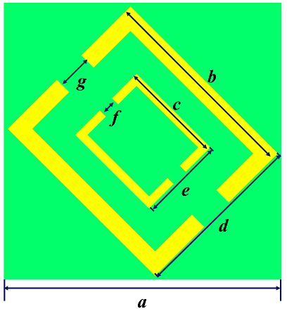
Fig. 1 Polarization converter schematic illustration
The SRRs are designed to achieve a resonant response at the desired frequencies, which enhances the polarization conversion efficiency. The metasurface was simulated using CST Microwave Studio, Finite Difference Time Domain (FDTD) approach in a full-wave simulator. Floquet ports were applied to extract the S-parameters, and frequency domain solvers were used for performance analysis.
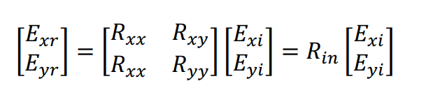
The anisotropic nature of the metasurface design causes the formation of components that are cross-polarized and co-polarized when a linearly polarized wave is reflected. Equation (1) illustrates how the Jones Reflection Matrix describes the relationship between the incident and reflected fields.
 (1)
(1)
The reflection coefficients that are co-polarized are represented by Ryy = |Eyr| / |Eyi| and Rxx = |Exr| / |Exi|, while for the cross-polarized reflection coefficients the values of Rxy = |Exr| / |Eyi| and Ryx = |Eyr| / |Exi|. In what follows, the Jones Reflection Matrix is represented by Rin. For example with regards to incident electromagnetic waves, it is believed that the electric field is along the y-axis as shown in the fig (2) below. Cross polarization conversion is a process, in which an x- polarized electromagnetic wave is reflected as y- polarized wave and vice versa. The reflected field will most often also consist of both x-polarized and y-polarized components despite the fact that one of these components may be dominant. Even in the equations E is used as the representation of electric field, “i” indicating the incident form of wave and ”r” for the reflected wave.
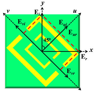
Fig. 2 Schematic design of proposed metasurface
III. RESULTS AND DISCUSSION
The performance of the designed metasurface was evaluated based on several key metrics: reflection coefficients, polarization conversion ratio (PCR), azimuth angle, and surface current distribution.
A. Reflection coefficients
The reflection coefficients of the designed metasurface were also calculated analytically and using the numerical approach in the frequency range of 8 GHz to 20 GHz. It can be seen from Fig. 3 that the metasurface has very good cross-polarization conversion performances which makes it suitable for practical use. Across the complete frequency range the cross-polarization reflection is more than 90%, with cross polarized reflection reaching nearly 100 % at the three resonance frequencies of 9.30 GHz, 13.69 GHz and 18.48 GHz.
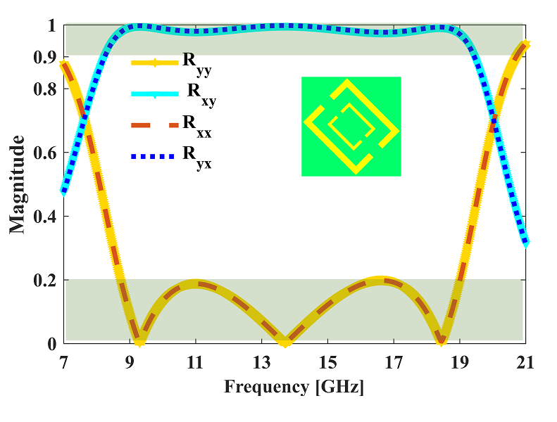
Fig. 3: Reflection coefficient results
B. Polarization Conversion Ratio (PCR)
To determine the ratio of change of the cell’s polarisation after the process, the polarisation conversion ratio (PCR) was calculated. The PCR is above 95% for the entire instance at the P and S plane of the frequency spectrum, as shown in Fig. 4; the maximum PCR at the resonant frequency of 9.30GHz, 13.69GHz and 18.48GHz occured at 100%. As for the broadband polarisation control applications, they are illustrated by the high conversion efficiency of the metasurface.
C. Azimuth Angle
At the resonance frequencies, the azimuth angle—a measure of the rotation of the reflected wave's polarisation plane—was assessed. The azimuth angle approaches 90° for the resonance frequencies of 9.30 GHz, 13.69 GHz, and 18.48 GHz, demonstrating that the reflected wave's polarisation state is rotated by roughly 90° as depicted in Fig. 5.
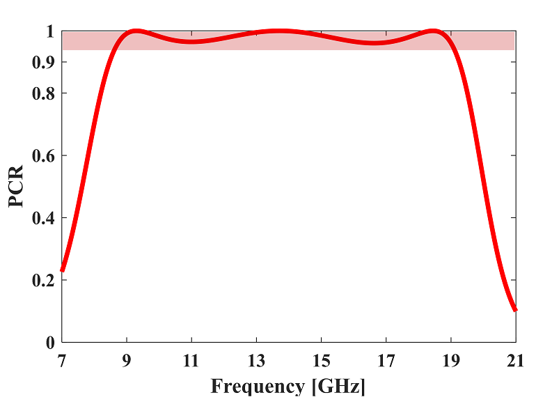
Fig. 4 PCR
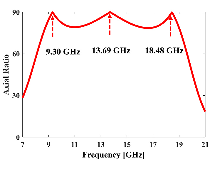
Fig. 5: Azimuth Angle
D. Structural Symmetry and Surface Current Distribution
For the stability on the metasurface in angular direction, in addition to the polarisation conversion ability, structural symmetry was analyzed.
The metasurface exhibits a comparable efficiency for all the angles of incidence as determined by assessment in Fig. 6. The explanation of cross-polarization conversion was made easier thanks to the distribution of currents on the surface at the resonance frequencies, while highlighting that magnetic resonances occur at the maximum frequencies.
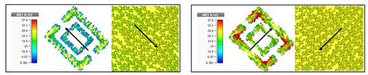
Fig. 6 Surface Current Distribution
Conclusion
This Study examines designs and analysis of the anisotropic metasurface reflector promising high cross-polarization conversion efficiency. A broadband operation was also indicated by the polarisation conversion ratio of the metasurface of over 95 % over the 820 GHz frequency. The metasurface exhibited nearly 100% of cross-polarization conversion at three resonance frequencies of 9.30?GHz, 13.69?GHz, and 18.48?GHz. For this reason, metasurface is preferable for use in communication and sensing systems where there is great need for the control of polarisation. Future investigations will be focused mainly by studying the performance of the metasurface with respect to the oblique angles of incidence. The utilisation of tuneable materials in order to switch the polarisation conversion capability of the metasurface will also be explored; this will have reactive and dynamic applications for the topological structure.
References
[1] Broadband polarization rotator based on multi-order plasmon resonances and high impedance surfaces Journal of Applied Physics 114, 074508 (2013) [2] An angularly stable dual-broadband anisotropic cross polarization conversion meta-surface M. Ismail Khan, and Farooq A. Tahir, Citation: Journal of Applied Physics 122, 053103 (2017). [3] Y. J. Chiang, T. J. Yen, Appl. Phys. Lett. 102, 011129 (2013). [4] J. Y. Chin, M. Lu, and T. J. Cui, Appl. Phys. Lett. 93, 251903 (2008). [5] H. F. Contangoes, C. A. Pyramidon, W. M. Merrill, and N. G. Iliopoulos, J. Opt. Soc. Am. A 16, 1682 (1999) [6] J. Zhao, Y. Chen, and Y. Feng, Appl. Phys. Lett. 92, 071114 (2008) [7] V. G. Veselago, “The electrodynamics of substances with simultaneously negative values of \"?, and ?”, Sov. Phys.Usp, Vol. 47, pp.509–514, Jan.– Feb, 1968. [8] Pendry, J.B., Holden, A.J., Robbins, D.J. and Stewart, W.J., 1999. Magnetism from conductors and enhanced nonlinear phenomena. IEEE transactions on microwave theory and techniques, 47(11), pp.2075-2084 . [9] Smith D R, Padilla W J, Vier D C, Nemat-Nasser S C and Schultz S 2000 Composite medium with simultaneously negative permeability and permittivity Physical Review Letters 84 4184–4187. [10] Li, X., Pu, M., Wang, Y., Ma, X., Li, Y., Gao, H., Zhao, Z., Gao, P., Wang, C. and Luo, X., 2016. Dynamic control of the extraordinary optical scattering in semicontinuous 2D metamaterials. Advanced Optical Materials. [11] Vafapour, Z. and Alaei, H., 2016. Subwavelength Micro-Antenna for Achieving Slow Light at Microwave Wavelengths via Electromagnetically Induced Transparency in 2D Metamaterials. Plasmonics, pp.1-10. [12] Rajput, A. and Srivastava, K.V., 2014. Design of a two-dimensional metamaterial cloak with minimum scattering using a quadratic transformation function. Journal of Applied Physics, 116(12), p.124501. [13] Hoefer, W.J., So, P.P., Thompson, D. and Tentzeris, M.M., 2005, June. Topology and design of wide-band 3D metamaterials made of periodically loaded transmission line arrays. In Proc. IEEE Int. Symp. Microwave Theory and Tech., Long Beach, CA (pp. 313-316). [14] Fan, K., Strikwerda, A.C., Zhang, X. and Averitt, R.D., 2013. Three-dimensional broadband tunable terahertz metamaterials. Physical Review B, 87(16), p.161104. [15] Gansel, J.K., Thiel, M., Rill, M.S., Decker, M., Bade, K., Saile, V., von Freymann, G., Linden, S. and Wegener, M., 2009. Gold helix photonic metamaterial as broadband circular polarizer. Science, 325(5947), pp.1513-1515. [16] Vignolini, S., Yufa, N.A., Cunha, P.S., Guldin, S., Rushkin, I., Stefik, M., Hur, K., Wiesner, U., Baumberg, J.J. and Steiner, U., 2012. A 3D optical metamaterial made by self?assembly. Advanced Materials, 24(10). [17] Liu, Z., Du, S., Cui, A., Li, Z., Fan, Y., Chen, S., Li, W., Li, J. and Gu, C., 2017. High?Quality?Factor Mid?Infrared Toroidal Excitation in Folded 3D Metamaterials. Advanced Materials, 29(17). [18] https://www.researchgate.net/figure/A-prototype-magnetic-metasurface [19] Simovski C R 2011 On electromagnetic characterization and homogenization of nanostructured metamaterials J. Opt. 13 013001. [20] Kuester E F, Mohamed M A, Piket-May M and Holloway C L 2003 Averaged transition conditions for electromagnetic fields at a metafilm IEEE Trans. Antennas Propag. 51 2641. [21] Zhao Y, Engheta N and Alu A 2011 Homogenization of plasmonic metasurfaces modeled as transmission-line loads Metamaterials [22] Costa, F., Monorchio, A. and Manara, G., 2014. An overview of equivalent circuit modeling techniques of frequency selective surfaces and metasurfaces. Appl. Comput. Electromagn. Soc. J., 29(12), pp.960-976. [23] Sounas, D.L., Kodera, T. and Caloz, C., 2013. Electromagnetic modeling of a magnetless nonreciprocal gyrotropic metasurface. IEEE Transactions on Antennas and Propagation.
Copyright
Copyright © 2025 Engr. Muhammad Asif Ramzan, Umair Iftikhar Tauni, Mudassir Murtaza, Dr. Shahzada Alamgir Khan. This is an open access article distributed under the Creative Commons Attribution License, which permits unrestricted use, distribution, and reproduction in any medium, provided the original work is properly cited.

Download Paper
Paper Id : IJRASET68969
Publish Date : 2025-04-15
ISSN : 2321-9653
Publisher Name : IJRASET
DOI Link : Click Here
 Submit Paper Online