

Ijraset Journal For Research in Applied Science and Engineering Technology
Home Automation System Using Based on IoT
Authors: Prithwish Parial, Debrupa Pal
DOI Link: https://doi.org/10.22214/ijraset.2022.45184
Certificate: View Certificate
Abstract
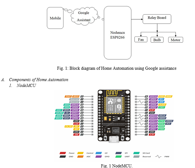
This paper has shown an automation proposal that represents how IoT-based systems are making human life easier with the help of Google Assistant. It helps to control the automation of lighting, air conditioning, and CCTV security, as well as home appliances. Automation systems also control the excessive usage of electricity. Google Assistant is one of the greatest home companions that controls every IoT-based home appliance with the good interaction of Wi-Fi modules. It also provides good coverage of Wi-Fi-connected devices. Wi-Fi is frequently used for the facility of remote monitoring. The remotely monitored and controlled home devices connected via the Internet is a part of the Internet of things(IoT). So overall, we can perceive that developing our home smart that also provides a better management system without any human intervention. This document describes the implementation of such systems.
Introduction
I. INTRODUCTION
A.. Introduction to Home Automation
One of the greatest things is that modern technology has determined human life with the help of automation. Technology is purposefully providing additional convenience towards the mankind. The recent world scenario technology automation wherein most of the systems have become machine-driven, such as industrial automation, home automation, and other substitute business sectors. “Home automation” defines a system that is automatic and electronic that controls household features and facilities, activities, and appliances through Wi-Fi modules. The home utility features can be easily operated via the Internet. There are many elements of a home automation system but there are three main elements like sensors, controllers, and actuators. Home automation systems are typically into three types: Power line Based Home Automation Wired or BUS Cable Home Automation Wireless Home Automation. It is burdensome with accustomed controls to overcome the problem of being away from home. It would be finer that if every essential work of daily life were done by voice commands before you even get into your house. Suppose someone is arriving at home exhaustedly and found that room temperature, room light, and also such things working like their own preferences accordingly, and they could immediately relax and feel more comfortable and pleasant at home. [1]
B. Introduction to IoT
The Internet of Things (or commonly referred to as IoT),This System is for Home Automation, This is a Smart the home controller that controls every device of your smart home via internet protocols connected to the Wi-Fi module The IoT based Home Automation system provides many good flexibilities over the wired systems it comes with various advantages like ease-of-use, ease-of-installation, avoiding the complexity of running through wires or loose electrical connections, easy fault detection and triggering and above and all it even offers easy mobility. [2]
II. LITERATURE SURVEY
This paper is written to sown crucial implementation of a smart home system with enhanced authorization and security and privacy practices, in view of the detailed description of different technologies present nowadays. The work is concluded by giving future directions to smart home Security Research. Internet-based smart home systems as it is a very demanding choice among researchers every time. The Internet is easily scalable and easily accessible when it comes to access and use, and very popular as well as common as a communication method in today’s world. [3]
III. METHODOLOGY
In this working framework, the locally situated keen Automation framework assesses the development of a Low-cost security framework utilizing motion sensors and IOT. the human development is distinguished by using the Motion sensors. This very responsive approach has low computational essentials.
Basically, this radiation is not unmistakable to the human eye since it emanates at infrared wavelengths, this infrared wavelength can be identified by electronic gadgets intended for identifying human development. The Distance Sensor has a scope of around 20 feet (6 meters). The sensor is intended to differentiate the slowly changing conditions that would typically happen as the everyday advances and the ecological condition changes. [4]
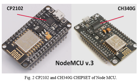
The NodeMCU (Node Microcontroller Unit) is an open source software and hardware development environment that is built around a very inexpensive System-on-a-Chip (SoC) called the ESP8266. The ESP8266, designed and manufactured by Expressive Systems, contains all crucial elements of the modern computer: CPU, RAM, networking (Wi-Fi), and even a modern operating system and SDK. When purchased at bulk, the ESP8266 chip costs only $2 USD a piece. That makes it an excellent choice for IoT projects of all kinds. Through its pins we can read inputs - light on a sensor, a finger on a button, or a Twitter message -and turn them into an output - activating a motor, turning on an LED, publishing something online. It has also Wi-Fi capabilities, so we can control it wirelessly and make it work on a remote installation easily! We can tell our board what to do by sending a set of instructions to the microcontroller on the board. [5]
2. NodeMCU ESP8266 Specifications & Features:
- Microcontroller: Tensilica 32-bit RISC CPU Xtensa LX106
- Operating Voltage: 3.3V
- Input Voltage: 7-12V
- Digital I/O Pins (DIO): 16
- Analog Input Pins (ADC): 1
- UARTs: 1
- SPIs: 1
- I2Cs: 1
- Flash Memory: 4 MB
- SRAM: 64 KB
- Clock Speed: 80 MHz
- USB-TTL based on CP2102 is included onboard, Enabling Plug n Play
- PCB Antenna
- Small Sized module to fit smartly inside your IoT projects
3. NodeMCU Pinout and Functions Explained:
- Power Pins
There are four power pins in NodeMCU. VIN pin and three 3.3V pins. VIN used to directly supply the NodeMCU/ESP8266 and its peripherals. Power distribution on VIN is regulated through the onboard regulator on the NodeMCU module we can also supply 5V regulated to the VIN pin. 3.3V pins are the output of the onboard voltage regulator and can be used to supply power to external components.
- GND
GND are basically ground pins of NodeMCU/ESP8266.
- I2C Pins
I2C Pins are used to connecting I2C sensors and peripherals. I2C interface functionality can be perceived programmatically, and the frequency of clock is 100 kHz at maximum. It should be noted that the I2C clock frequency should be higher than the slowest clock frequency of the slave device.
- GPIO Pins
There are 17 GPIO pins that can be assigned to functions such as I2C, I2S, UART, PWM, IR Remote Control, LED Light, and Button programmatically. Each digital-enabled GPIO can be customized to internal pull-up or pull-down, or set to high resistance. When configured as an input, it can also be set to edge-trigger or level-trigger, and also CPU interrupts occurs.
- ADC Channel
NodeMCU is embedded with a 10-bit precision SAR ADC. The two functions can be implemented using ADC. Testing power supply voltage of VDD3P3 pin and testing input voltage of TOUT pin. although they cannot be implemented at the same time.
- UART Pins
NodeMCU has 2 UART interfaces (UART0 and UART1) which gives asynchronous communication (RS232 and RS485), and can communicate at up to 4.5 Mbps. UART0 (TXD0, RXD0, RST0 & CTS0 pins) can be used for communication. although, UART1 (TXD1 pin) characteristics only data transmit signal so that, it is usually used for printing log.
- SPI Pins
NodeMCU features two SPIs (SPI and HSPI) in slave and master modes.
4 timing modes of the SPI format transfer.
Up to 80 MHz and the divided clocks of 80 MHz.
Up to 64-Byte FIFO.
- SDIO Pins
Pins ESP8266 features Secure Digital Input/output Interface is used to directly interface SD cards. 4-bit and 25 MHz SDIO v1.1 and 4-bit and 50 MHz SDIO v2.0 are supported.
- PWM Pins
The board consists of 4 channels of Pulse Width Modulation. The PWM output can be implemented programmatically and used for driving digital motors and LED lights. PWM frequency range is adjustable from 1000 μs to 10000 μs, i.e., between 100 Hz and 1 kHz.
- Control Pins
Control Pins are used to controlling ESP8266. These pins contain the Chip Enable pin (EN), Reset pin (RST), and WAKE pin.
EN pin – The ESP8266 chip is enabled when the EN pin is pulled HIGH. pulled LOW the chip works at minimum power.
RST pin – It is used for resetting the ESP8266 chip. WAKE pin – This pin is used to wake the chip from a deep sleep.
TABLE 1
Pin configuration of NodeMCU
|
Pin |
Code |
Arduino alias |
|
A0 |
A0 |
A0 |
|
D0 |
GIPO 16 |
16 |
|
D1 |
GPIO 5 |
5 |
|
D2 |
GPIO 4 |
4 |
|
D3 |
GPIO 0 |
0 |
|
D4 |
GPIO 2 |
2 |
|
D5 |
GPIO 14 |
14 |
|
D6 |
GPIO 12 |
12 |
|
D7 |
GPIO 13 |
13 |
|
D8 |
GPIO15 |
15 |
|
SD2 |
GPIO 9 |
9 |
|
SD3 |
GPIO 10 |
10 |
|
RX |
GPIO 3 |
3 |
|
TX |
GPIO 1 |
1 |
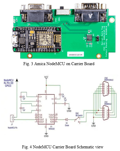
- CP2102 or CH340G (USB to Serial Converter)
Each NodeMCU is a USB to Serial Converter. The actual design is based on the CP2102 chipset and suggests the best compatibility. Genuine boards use the CP2102 chipset including the original licensed Amica NodeMCU modules. Another common USB to Serial Converter used is the CH340G. commonly on the cheap lower price modules including the LoLin units. Other designs may use drivers and also FTDI chipset. Generally, Windows 10 immediately recognizes the CP2102 chipset while the CH340G may require separate installation. [6]
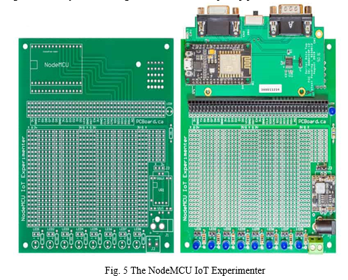
B. NodeMCU Carrier BoardNodeMCU Carrier Board with Serial Ports
The NodeMCU Carrier Board features a genuine Amica NodeMCU ESP8266 processor with a DB09 male connector and a female connector on an RS-232 level converter. The original design of the Carrier Board was for a Wi-Fi application and the serial ports permitted for RS-232 data to be provided over the serial connectors, through a MAX232 compatible level converter to the NodeMCU.
The NodeMCU Carrier Board schematic denotes the two DB-09 connectors, along with the switch at SW1. The switch toggles the data from additionally DB-09 between Pin 2 or Pin 3 to the level converter ultimately, there is a jumper position at J1. This allows serial data from either DB-09 to appear on the NodeMCU Rx pin.
C. The NodeMCU IoT Experimenter
NodeMCU IoT Experimenter is an advanced, versatile, and simply adjustable prototyping platform, it consists of varied varieties of the foremost widespread NodeMCU modules with the NodeMCU Carrier Board.The NodeMCU IoT Experimenter measures 135mm x 115mm with a solder mask on each side, plated holes along with a high-contrast silk-screen labelling component, and prototyping positions. Features of this board include a mounting socket area to accept either wide 1.1″ or narrow 0.9″ pitch NodeMCU modules. This embraces the Amica NodeMCU carrier board to compatible types such as the LoLin NodeMCU models. Power can be given directly to the NodeMCU module through its built-in USB interface. instead, power can be supplied to the IoT Experimenter board which has delivering for an integrated regulated power supply module. The board has over 1,000 plated-through holes on the prototype surface, mounting for eight status indicator LEDs along with dropping resistors and a power indicator LED. The prototyping area offers power busbars for the Ground (G), +3.3V (3V) power rail, and a third rail X. The third rail is used for external voltages like 5V rail.
The NodeMCU Interface is through a series of headers that expand each of every pin of the NodeMCU to rows of four headers. Each port is labeled to point out matching pins from the NodeMCU. The header area is located below the NodeMCU using standard 40-pin headers allowing for versatility in interfacing for sockets or header pins. [7]
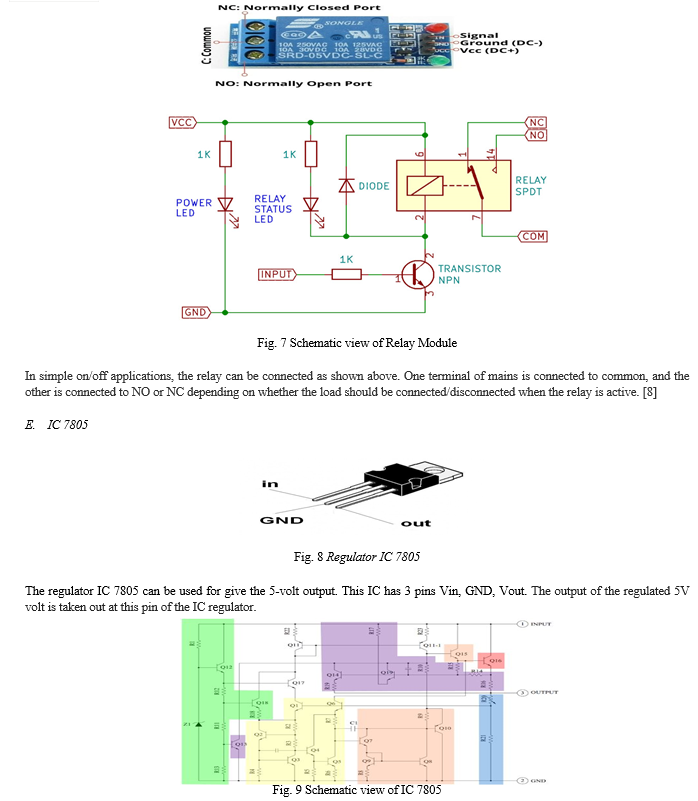
D. Relay Module
The relay is the component that opens or closes the contacts to cause the operation of another electric control. It tracks down the undesirable condition with an assigned area and gives the commands to the circuit breaker to disconnect the affected area through ON or OFF. [8]
Every electromechanical relay consists of followings:-
- Electromagnet
- Mechanically movable contact
- Switching points
- Spring
- COM
It is a common pin.
- 0NO
No stand for Normally open, there is no connection between the common pin and the normally open pin. So, triggering the relay, it communicates to the COM pin, and power is provided to the load.
- NC
NC stands for Normally closed, there is a connection between the common pin and the normally closed pin. There is a connection between the COM pins and NC pins, even when the relay is turned off and triggering the relay, the circuit is opened and there is no power supply provided to the load.
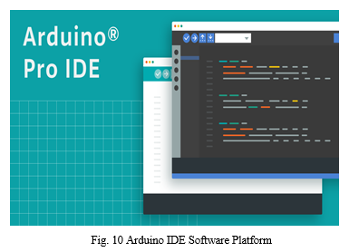
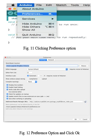
The main thing of the 7805 IC is a transistor (Q16) that helps to controls the current in between the input and output and therefore controls the voltage of the output. The bandgap reference keeps the voltage stable. It takes the scaled output voltage input (Q1 and Q6) and provides an error signal (to Q7) for indication if the voltage is too high or low. The key task of the bandgap is to give a still and accurate reference, even as the chip’s temperature changes. The error signal from the bandgap reference is amplified with the help of the error amplifier. This amplified signal manages the output transistor through Q15. This closes the negative feedback loop controlling the output voltage. The start-up circuit provides initial current to the bandgap circuit, so it doesn’t get stuck and interrupted in an “off” state. The circuit provides safety in case of overheating (Q13), excessive input voltage (Q19) and excessive output current (Q14). These circuits decrease the output current and the regulator, preventing it from damage or fault. The voltage divider scales down the voltage on the output pin for use by the bandgap reference. [9]
F. Software Platform
The Arduino IDE platform is used for coding the Nodemcu. This Software platform provides to work with a few programming languages. E.g. C, C++. This software is absolutely open-source and freely available on the online market. This platform provides us the many types of boards which can be Arduino UNO, Nano, Mega, NodeMCU, and many more. [10]
IV. WORKING OF PROJECT
In this project We are going show about controlling LED lights using web application over Wi-Fi using ESP8266(NodeMCU) module and Arduino board. [11]
A. Required Components:
- Arduino Board
- LED lights
- Breadboard
- Some male and female connecting wires
- Laptop
For this, we need Arduino 1.6.4 or higher. Open the Arduino IDE and then go to the File -> Preferences (in Windows shortcut is Ctrl+comma) or Arduino -> Preferences (in Mac shortcut is ?+comma). In Preferences, “Additional Board Manager’s URL” bottom: http://arduino.esp8266.com/package_esp8266com_index.json [12]
After that, click OK.
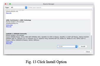
After doing those followings restart Arduino IDE. Now go to Tools -> Board -> Boards Manager… In the Boards Manager, search by esp. You will find something like ‘esp8266 by ESP8266 Community ‘, click on that and then Install button. After installation Close it and restart the Arduino IDE [13]
Go to Tools -> Board -> Generic ESP8266 Module (this is the new updated module).
Follow the given things for few other settings in Tools menu: -
- Flash Mode: DIO
- Flash Frequency: 40 MHz
- Upload Using: Serial
- CPU Frequency: 80 MHz
- Flash Size: 4M (1M SPIFFS)
- Upload Speed: 115200
- Port: my USB port (this shows up once you plugged Arduino board to laptop )
- Programmer: AVRISP mkll
Leave other settings as default.
G. Install the ArduinoJSON library: -
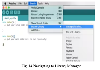
In the HTML app, we can perform tasks with JSON data. That’s Why we are required to add the ArduinoJson library to the Arduino IDE platform. ArduinoJson is freely available in Arduino’s Library Manager. You can automatically install it from there. To open Library Manager go to Sketch -> Include Library -> Manage Libraries… and search by ‘JSON ‘. You will get something like ‘ArduinoJSON by Benolt Blanchon ‘click on it and click on the Install button. If you are getting some kind of problem in installing the library then follow the given link to install the ArduinoJsonlibrary (https://github.com/bblanchon/ArduinoJson). After setting up this, now you can include this library with #include in the sketch. [14]
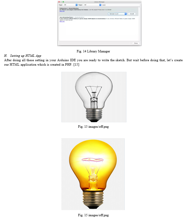
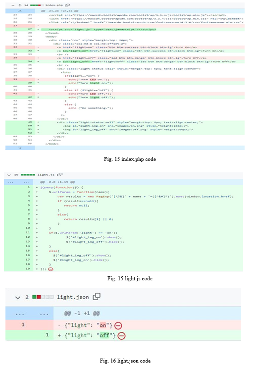
Make sure that you should have Apache and PHP installed on your laptop. You can do it simply with Google. After setting up Apache and PHP, start your Apache server and test it. Open your web browser and type (http://localhost/your-HTML-app-folder-name) to the URL. You will get your running HTML application. In our HTML app, there are two things one is index.php and another one is a light.json file. The light.json file is very simple. It either reads {“light”:” on”} or {“light”: “off”}. Keep in mind, that it needs to be set to permission 777 or 666 so the PHP file can write to it. The index.php file is public file that writes {“light”:”on”} or {“light”: “off”} to light.json. There are two links that link you to the current page with a URL parameter (?light=on) or (?light=off). Based on the URL parameter, the PHP writes the specific instructions to the JSON file. [16]
Wiring up everything:-
Here we are not using FTDI to USB cable. So that, we are going to use our Arduino board behave like FTDI for that we have removed the ATmega chip. carefully removing the chip don’t damage it.
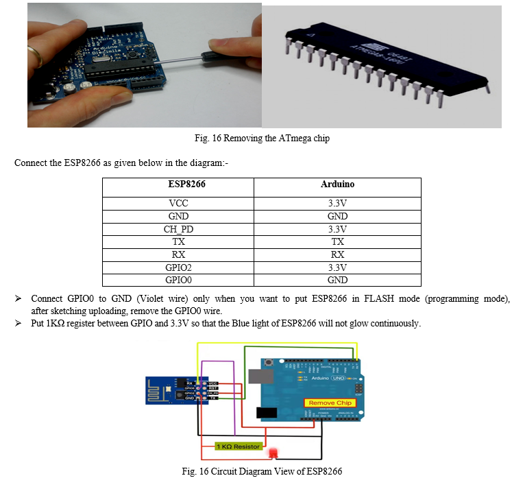
- Power up ESP8266: Keep in mind ESP8266 module performs on low voltage (3.3V DC). Connect the VCC and the CH_PD of the ESP8266 to 3.3V of the Arduino board. implement a 1KΩ resistor between GPIO2 and 3.3V power supply.
- Connecting TX/RX Pins: The TX/RX pins are used to program the module and for Serial I/O, basically used for debugging. Connect the ESP9266’s TX -> TX and RX->RX from the Arduino board.
- Putting ESP8266 in FLASH Mode: When GPIO0 (the Violet colored wire in the upper diagram) is connected to the ground at the boot, this tells the ESP8266 to start up in bootloader mode (or programming mode). Here you can flash the ESP8266, meaning transfer the Arduino code to the ESP8266. After the Arduino code is loaded, “Done Uploading” message at the bottom of the Arduino IDE. Then the code will start running. uploading the program then remove the Violet wire. We previously installed crucial libraries to work with ESP8266. Now we are using header files. library, basically tells to the ESP to ping our light.json file. If the latest value is for the light is on, then turn on the LED and if the value for the light is off, then turn off the LED. Here, light.json outputs its value using JSON.[17]
This is the code:
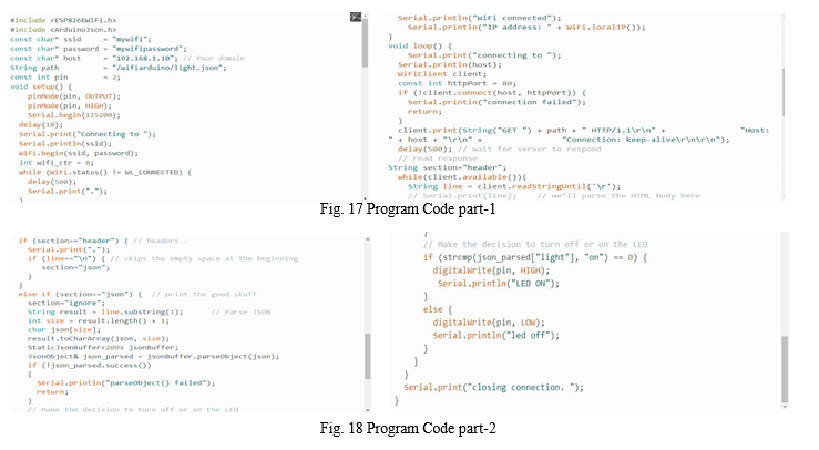
Void setup(): Now setting up some basic configurations set to our specific values like:-
- Wi-Fi name and password (the SSID & password variables)
- light.json URL
- Output pin (we use GPIO2, so const int pin=2) We begin a Serial Connection using Serial. begin(115200). Here we set the baud rate to 115200. Set the same Baud Rate on the Serial Monitor of Arduino IDE to see the response output from ESP8266. Then we starting to connect the internet using Wi-Fi(SSID and PASS) [18]
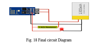
I. Final Things to Do
As I already mention to remove the Violet wire after uploading the code. Now go on Arduino IDE Platform and then go to Tools > Serial Monitor. Change the baud rate to 115200 baud from the right bottom in Serial Monitor. It will show you whether is connected to your Wi-Fi or not. If you see the red light turn on permanently and the blue light flashes or blinks, it means your module is ready to use. In the end, just remove RX and TX pins. And finally power on, just remove RX and TX pins. And power up ESP8266 with an external power source like a 3.3V rechargeable good battery or something other with the same DC voltage. So, this is the final circuit diagram after completion. That’s All. [19]
Conclusion
In this paper, we are implementing a simple IoT project. The purpose of the task is to propose a price-productive home mechanization dominant general apparatus found in one’s home. The methodology talked about the task was useful and also the structure is basically effective. This framework is very powerful and productive for the matured individual and distinctively ready individual with a practical approach.
References
[1] Mr. G. Chenna Keshava Reddy, A. Sai Divya, G. Sunil Reddy, M Pravalika Reddy, Viharika Sri Sai Durga V, “Google Voice Assistance based Smart Home Automation Using Artificial Intelligence”, International Journal of Innovative Research in Technology, IJIRT, Volume 8 Issue 1, June 2021. [2] Building Blocks for IoT Analytics Internet-of-Things Analytics by River Publishers [3] Literature Review on Home Automation System International Journal of Engineering Research in Computer Science and Engineering(IJERCSE)Vol 4, Issue 6, June 2017 ISSN (Online) 2394-2320 [4] Home automation using IOT application International Journal of Smart Home Vol. 11, No. 9 (2017), pp. 1-8 http://dx.doi.org/10.21742/ijsh.2017.11.09.01 [5] NodeMCU ESP8266 Detailed Review Specifications, Overview and Setting Up Your NodeMCU. https://www.make-it.ca/nodemcu-details-specifications/ [6] Electronics Projects with the ESP8266 and ESP32 Building Web Pages Applications and Wi-Fi Enabled Devices 2021 Edition by Neil Cameron , Apress [7] NodeMCU IoT Experimenter Prototype Board PCBoard.ca 4646 Heritage Hills Blvd., Suite 14617 Mississauga, Ontario Canada L5R 4G3 www.pcboard.ca https://www.make-it.ca/wp-content/uploads/2021/09/nodemcu-iot-experimenter.pdf [8] Relay Module Design View https://components101.com/switches/5v-single-channel-relay-module-pinout-features-applications-working-datasheet [9] THERMAL- ELECTRICAL SIMULATION AND ANALYSIS OF LM7805 IC FORELECTRONICS POWER SUPPLY ADAPTER Indian J.Sci.Res. 20(2): 101-107, 2018 ISSN: 0976-2876 (Print) ISSN: 2250-0138(Online) [10] Arduino Measurement Projects for Beginners: Arduino Programming basics and Get started guide by Simone bales [11] Control LED from web app using ESP8266 Serial WIFI module project by Jai Prak https://create.arduino.cc/projecthub/jaiprak/control-led-from-web [12] https://hacksterio.s3.amazonaws.com/uploads/attachments/191166/package_esp8266com_index.json [13] Arduino IDE https://www.arduino.cc/en/software [14] Arduino json Library https://github.com/bblanchon/ArduinoJson [15] Index.php https://github.com/Arduino-and-RaspberryPi/Controlling-LED-using-ESP8266-UI [16] Light.json https://github.com/Arduino-and-RaspberryPi/Controlling-LED-using-ESP8266-UI/blob/master/light.js [17] https://arduinojson.org/ [18] Arduino IDE: https://www.arduino.cc/en/Guide/Environment [19] Wkipedia: https://www.wikipedia.org
Copyright
Copyright © 2022 Prithwish Parial, Debrupa Pal. This is an open access article distributed under the Creative Commons Attribution License, which permits unrestricted use, distribution, and reproduction in any medium, provided the original work is properly cited.

Download Paper
Paper Id : IJRASET45184
Publish Date : 2022-07-01
ISSN : 2321-9653
Publisher Name : IJRASET
DOI Link : Click Here
 Submit Paper Online