

Ijraset Journal For Research in Applied Science and Engineering Technology
Localized Network Reconfiguration Plan for Wireless Mesh Networks
Authors: Ranjith Pulyala
DOI Link: https://doi.org/10.22214/ijraset.2022.41305
Certificate: View Certificate
Abstract
Wireless mesh networks (WMNs) have emerged as a key technology for next-generation wireless networking. Because of their advantages over other wireless networks, WMNs are undergoing rapid progress and inspiring numerous applications. In multi-hop wireless mesh networks (WMNs) experience frequent link failures caused by channel interference, dynamic obstacles and/or applications’ bandwidth demands. These failures cause severe performance degradation in WMNs or require expensive, manual network management for their real-time recovery. This paper presents an Autonomous network Reconfiguration System (ARS) that enables a multi-radio WMN to autonomously recover from local link failures to preserve network performance. ARS also improves channel efficiency by more than 90% over the other recovery methods. During their lifetime, multi-hop wireless mesh networks (WMNs) experience frequent link failures caused by channel interference, dynamic obstacles, and/or applications’ bandwidth demands. These failures cause severe performance degradation in WMNs or require expensive manual network management for their real-time recovery. By using channel and radio diversities in WMNs, ARS generates necessary changes in local radio and channel assignments in order to recover from failures. Next, based on the thus-generated configuration changes, the system cooperatively reconfigures network settings among local mesh routers. ARS has been evaluated extensively through ns2-based simulation. Our evaluation results show that ARS outperforms existing failure-recovery schemes in improving channel-efficiency by more than 90% and in the ability of meeting the applications’ bandwidth demands by an average of 200%.
Introduction
I. INTRODUCTION
Wireless networks provide unprecedented freedom and mobility for a growing number of laptop and PDA users who no longer need wires to stay connected with their workplace and the Internet. Ironically, the very devices that provide wireless service to these clients need lots of wiring themselves to connect to private networks and the Internet. This white paper presents a viable alternative to all those wires - the wireless mesh network. Unlike basic Wi-Fi that simply untethers the client; the wireless mesh untethers the network itself giving IT departments, network architects and systems integrators unprecedented freedom and flexibility to build out networks in record time - with high performance and without the expensive cabling.
A wireless mesh network (WMN) is a communications network made up of radio nodes organized in a mesh topology. Wireless mesh networks often consist of mesh clients, mesh routers and gateways. The mesh clients are often laptops, cell phones and other wireless devices while the mesh routers forward traffic to and from the gateways which may but need not connect to the Internet. The coverage area of the radio nodes working as a single network is sometimes called a mesh cloud. Access to this mesh cloud is dependent on the radio nodes working in harmony with each other to create a radio network. A mesh network is reliable and offers redundancy. When one node can no longer operate, the rest of the nodes can still communicate with each other, directly or through one or more intermediate nodes. The animation below illustrates how wireless mesh networks can self-form and selfheal. Wireless mesh networks can be implemented with various wireless technology including 802.11, 802.15, 802.16, cellular technologies or combinations of more than one type. A wireless mesh network can be seen as a special type of wireless ad-hoc network. A wireless mesh network often has a more planned configuration, and may be deployed to provide dynamic and cost effective connectivity over a certain geographic area. An ad-hoc network, on the other hand, is formed ad hoc when wireless devices come within communication range of each other. The mesh routers may be mobile, and be moved according to specific demands arising in the network. Often the mesh routers are not limited in terms of resources compared to other nodes in the network and thus can be exploited to perform more resource intensive functions. In this way, the wireless mesh network differs from an ad-hoc network, since these nodes are often constrained by resources. Nodes are comprised of mesh routers and mesh clients. Each node operates not only as a host but also as a router, forwarding packets on behalf of other nodes that may not be within direct wireless transmission range of their destinations.
A WMN is dynamically self-organized and self-configured, with the nodes in the network automatically establishing and maintaining mesh connectivity among themselves. Extend the range and link robustness of existing Wi-Fi’s by allowing mesh-style multi-hopping. A user finds a nearby user and hops through it - or possibly multiple users - to get to the destination Every user becomes a relay point or router for network traffic Mesh networks consist of multiple wireless devices equipped with COTS802.11 a/b/g cards that work in ad-hoc fashion 802.11 capable antennas placed on rooftops allow a large area coverage.
A. Basic Idea
To meet the increasing capacity demands by the widely for a variety of applications, Such as public safety, environment monitoring, and citywide wireless Internet services and other emerging applications. However, due to heterogeneous and fluctuating wireless link conditions preserving the required performance of such WMNs is still a challenging problem. For example, some links of a WMN may experience significant channel interference from other coexisting wireless networks. Some parts of networks might not be able to meet increasing bandwidth demands from new mobile users and applications. Links in a certain area (e.g., a hospital or police station) might not be able to use some frequency channels because of spectrum etiquette or regulation .Even though many solutions for WMNs to recover from wireless link failures have been proposed, they still have several limitations.
To overcome the limitations, Autonomous network reconfiguration system (ARS) is used, that allows a multi radio WMN (mr-WMN) to autonomously reconfigure its local network settings channel, radio, and route assignment for real-time recovery from link failures. In its core, ARS is equipped with a reconfiguration planning algorithm that identifies local configuration changes for the recovery while minimizing changes of healthy network settings. Briefly, ARS first searches for feasible local configuration hanges available around a faulty area, based on current channel and radio associations. Then, by imposing current network settings as constraints, ARS identifies reconfiguration plans that require the minimum number of changes for the healthy network settings.
B. Motivation
Maintaining the performance of WMNs in the face of dynamic link failures remains a challenging problem. However, such failures can be withstood (hence maintaining the required performance) by enabling mr-WMNs to autonomously reconfigure channels and radio1 assignments, as in the following examples.
- Recovering from link-quality degradation: The quality of wireless links in WMNs can degrade (i.e., link-quality failure) due to severe interference from other collocated wireless networks [8], [19]. For example, Bluetooth, cordless phones, and other coexisting wireless networks operating on the same or adjacent channels cause significant and varying degrees of losses or collisions in packet transmissions, as shown in Fig. 1. By switching the tuned channel of a link to other interference-free channels, local links can recover from such a link failure.
- Satisfying dynamic QoS demands: Links in some areas may not be able to accommodate increasing QoS demands from end-users (QoS failures) depending on spatial or temporal Locality. For example, links around a conference room may have to relay too much data/video traffic during the session. Likewise, relay links outside the room may fail to support all attendees’ voice-over-IP calls during a session break. By reassociating their radios/channels with underutilized radios/channels available nearby, links can avoid communication failures.
- Coping with heterogeneous channel availability: Links in some areas may not be able to access wireless channels during a certain time period (spectrum failures) due to spectrum etiquette or regulation. For example, some links in a WMN need to vacate current channels if channels are being used for emergency response near the wireless links (e.g., hospital, public safety). Such links can seek and identify alternative channels available in the same area. Motivated by these three and other possible benefits of using reconfigurable mr-WMNs, in the remainder of this paper, we would like to develop a system that allows mr-WMNs to autonomously change channel and radio assignments (i.e., self-reconfigurable) to recover from the channel-related link failures mentioned.
II. WIRELESS MESH NETWORKS
A. Wired Vs Wireless Networks
- Wired Networks: These networks are generally connected with the help of wires and cables. Generally the cables being used in this type of networks are CAT5 or CAT6 cables. The connection is usually established with the help of physical devices like Switches and Hubs in between to increase the strength of the connection. These networks are usually more e?cient, less expensive and much faster than wireless networks. Once the connection is set there is a very little chance of getting disconnected.
- Wireless Networks: Wireless networks provide unprecedented freedom and mobility for a growing number of laptop and PDA users who no longer need wires to stay connected with their workplace and the Internet. Ironically, the very devices that provide wireless service to these clients need lots of wiring themselves to connect to private networks and the Internet. This white paper presents a viable alternative to all those wires - the wireless mesh network. Unlike basic Wi-Fi that simply untethers the client; the wireless mesh untethers the network itself giving IT departments, network architects and systems integrators unprecedented freedom and flexibility to build out networks in record time - with high performance and without the expensive cabling.
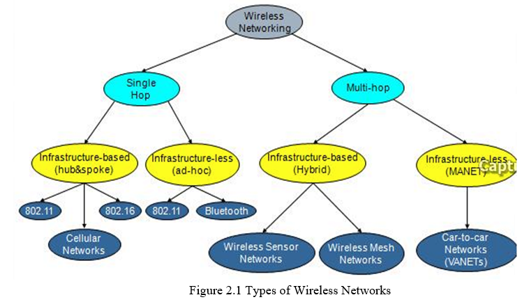
B. Types of Wireless Networks
One of the unique features of wireless networks is compare to wire network is that data is transmitted from one point to another through wireless links i.e. there is no need of wired link between the two nodes for transmission. They just need to be in the transmission range of each other. Wireless networks or divided into two categories. Infrastructure wireless network and infrastructure less or ad hoc wireless network.
- Infrastructure Networks: Infrastructure network have fixed network topology. Wireless nodes connect through the fixed point known as base station or access point. In most cases the access point or base station or connected to the main network through wired link. The base station, or access point, is one of the important elements in such types of networks. All of the wireless connections must pass from the base station. Whenever a node is in the range of several base stations then it connect to any one of them on the bases of some criteria.
- Ad hoc Networks: Ad hoc networks also called infrastructure less networks are complex distributed systems consist of wireless links between the nodes and each node also works as a router to forwards the data on behalf of other nodes. The nodes are free to join or left the network without any restriction. Thus the networks have no permanent infrastructure. In ad hoc networks the nodes can be stationary or mobile. Therefore one can say that ad hoc networks basically have two forms, one is static ad hoc networks (SANET) and the other one is called mobile ad hoc networks (MANET). From the introduction of new technologies such as IEEE 802.11 the commercial implementation of ad hoc network becomes possible. One of the good features of such networks is the flexibility and can be deployed very easily. Thus it is suitable for the emergency situation. But on the other side it is also very difficult to handle the operation of ad hoc networks. Each node is responsible to handle its operation independently. Topology changes are very frequent and thus there will be need of an efficient routing protocol, whose construction is a complex task. TCP performances are also very poor in mobile ad hoc network. In coming sections we are discussing the TCP working mechanism and challenges for TCP in ad hoc networks in more detail. Wireless networks use some sort of radio frequencies in air to transmit and receive data instead of using some physical cables. The most admiring fact in these networks is that it eliminates the need for laying out expensive cables and maintenance costs. A wireless mesh network can be seen as a special type of wireless ad-hoc network. A wireless mesh network often has a more planned configuration, and may be deployed to provide dynamic and cost effective connectivity over a certain geographic area. An ad-hoc network, on the other hand, is formed ad hoc when wireless devices come within communication range of each other. The mesh routers may be mobile, and be moved according to specific demands arising in the network. Often the mesh routers are not limited in terms of resources compared to other nodes in the network and thus can be exploited to perform more resource intensive functions. In this way, the wireless mesh network differs from an ad-hoc network, since these nodes are often constrained by resources. Nodes are comprised of mesh routers and mesh clients. Each node operates not only as a host but also as a router, forwarding packets on behalf of other nodes that may not be within direct wireless transmission range of their destinations. A WMN is dynamically self-organized and self-configured, with the nodes in the network automatically establishing and maintaining mesh connectivity among themselves. Extend the range and link robustness of existing Wi-Fi’s by allowing mesh-style multi-hopping. A user finds a nearby user and hops through it - or possibly multiple users - to get to the destination Every user becomes a relay point or router for network traffic Mesh networks consist of multiple wireless devices equipped with COTS802.11 a/b/g cards that work in ad-hoc fashion 802.11 capable antennas placed on rooftops allow a large area coverage .
- Mobile Ad-Hoc Networks: An ad-hoc network is a collection of wireless mobile hosts forming a temporary network without the aid of any stand-alone infrastructure or centralized administration. Mobile Ad-hoc networks are self-organizing and self- con?guring multihop wireless networks where, the structure of the network changes dynamically. This is mainly due to the mobility of the nodes. Nodes in these networks utilize the same random access wireless channel, cooperating in a friendly manner to engaging themselves in multihop forwarding. The node in the network not only acts as hosts but also as routers that route data to/from other nodes in network. In mobile ad-hoc networks where there is no infrastructure support as is the case with wireless networks, and since a destination node might be out of range of a source node transmitting packets; a routing procedure is always needed to ?nd a path so as to forward the packets appropriately between the source and the destination. Within a cell, a base station can reach all mobile nodes without routing via broadcast in common wireless networks. In the case of ad-hoc networks, each node must be able to forward data for other nodes. This creates additional problems along with the problems of dynamic topology which is unpredictable connectivity changes.
C. TCP Working Mechanism And Variants Of TCP
Transmission Control Protocol (TCP) is a Transport Layer Protocol and originally designed for wired network in 1981. The basic responsibility of TCP is to provide reliable transfer of data between the nodes i.e. to ensure that the data is reached the destination correctly without any loss or damage. The data is transmitted in the form of continuous stream of octets. The mechanism is adopted to assign a sequence number to each octet of data and receiver respond with positive acknowledgement to ensure that the data is received correctly. Another aspect of TCP is the tree way handshakes mechanism to establish a connection between the end points (nodes). In case if there are two or more TCP connection between the end points for this TCP uses the port assignment mechanism to differentiate each connection from others.
- Working Mechanism of TCP: The congestion control algorithm employed by TCP is window based. It uses three types of windows called congestion window (cwnd), advertize window (rwnd) and send window (swnd). Congestion windows shows the total amount of data the sender is allowed to output to the network without any Acknowledgement (ACK). While on the other hand the advertise window indicates the amount of data the receiver is ready to accept. It is equal to the available buffer size on the receiver. Now the size of the flight window or send window is set to the minimum of the congestion window and advertise window. Basically the congestion control mechanism has two phases the slow start and congestion avoidance phase. When a connection is established the initial size of congestion window is set to One MSS (Maximum Segment Size). Receiving data from the sender the receiver ACK the reception of data to the sender, the receiver is actually indicating the sequence number of next expected data segment in ACK, from this the sender conclude that all the data segments which have sequence number less than the indicated one are delivered correctly. While in case of packet loss, out-of-order packets arrive at the receiver. Then the receiver sends a duplicate ACK to the sender in response of each out-of-order packet arrival. When sender receives three duplicates ACK, it is concluded that the packet is lost and retransmission of data packet take place. If sender receives non-duplicate ACK Then the congestion window is incremented. In slow start phase exponential incrimination occurs until it reaches to the slow start threshold. While in congestion avoidance phase the cwnd is incremented by one packet. This window growth is limited to a maximum window size. This whole process is depicte1.
- Various Flavours of TCP: After the introduction of first version of TCP several different flavors exist, here we are discussing the most famous implementation of TCP called Tahoe, Reno, New Reno and Vegas.
- Tahoe: In the first version of TCP there was no congestion control mechanism. So after observing the congestion collapses Jacobson introduced several Congestion Control algorithms and this version is called TCP-Tahoe. The congestion control algorithms introduced in this version.
a. Slow start
b. Congestion Avoidance
c. Fast Retransmit
D. Problems in Wireless Communications
Some of the problems related to wireless communication are multipath propagation, path loss, interference, and limited frequency spectrum. Multipath Propagation is, when a signal travels from its source to destination, in between there are obstacles which make the signal propagate in paths beyond the direct line of sight due to re?ections, refraction and di?raction and scattering. Path loss is the attenuation of the transmitted signal strength as it propagates away from the sender. Path loss can be determined as the ratio between the powers of the transmitted signal to the receiver signal.
This is mainly dependent on a number of factors such as radio frequency and the nature of the terrain. It is sometimes important to estimate the path loss in wireless communication networks.
Due to the radio frequency and the nature of the terrain are not same everywhere, it is hard to estimate the path loss during communication. During communication a number of signals in the atmosphere may interfere with each other resulting in the destruction of the original signal. Limited Frequency Spectrum is where, frequency bands are shared by many wireless technologies and not by one single wireless technology.
Wireless mesh networks (WMNS) are being developed actively and deployed widely for a variety of applications, such as public safety, environment monitoring, and citywide wireless Internet services. They have also been evolving in various forms (e.g., using multi radio/channel systems) to meet the increasing capacity demands by the above-mentioned and other emerging applications. However, due to heterogeneous and fluctuating wireless link conditions, preserving the required performance of such WMNs is still a challenging problem. For example, some links of a WMN may experience significant channel interference from other coexisting wireless networks. Some parts of networks might not be able to meet increasing bandwidth demands from new mobile users and applications. Links in a certain area (e.g., a hospital or police station) might not be able to use some frequency channels because of spectrum etiquette or regulation
Even though many solutions for WMNs to recover from wireless link failures have been proposed, they still have several limitations.
E. Network Architectures
Wireless mesh architecture is a first step towards providing cost effective and dynamic high-bandwidth networks over a specific coverage area. Wireless mesh architectures infrastructure is, in effect, a router network minus the cabling between nodes. It's built of peer radio devices that don't have to be cabled to a wired port like traditional WLAN access points (AP) do. Mesh architecture sustains signal strength by breaking long distances into a series of shorter hops. Intermediate nodes not only boost the signal, but cooperatively make forwarding decisions based on their knowledge of the network, i.e. perform routing. Such architecture may with careful design provide high bandwidth, spectral efficiency, and economic advantage over the coverage area. Wireless mesh networks have a relatively stable topology except for the occasional failure of nodes or addition of new nodes. The path of traffic, being aggregated from a large number of end users, changes infrequently. Practically all the traffic in an infrastructure mesh network is either forwarded to or from a gateway, while in ad hoc networks or client mesh networks the traffic flows between arbitrary pairs of nodes.
There are different types of wireless networks are being used across for various communications. They are
- Infrastructure based networks
- Rapidly deployable networks
- Hybrid Networks
Infrastructure networks contain special nodes called access points (APs), which are connected via existing networks. APs are special in the sense that they can interact with wireless nodes as well as with the existing wired network. The other wireless nodes, also known as mobile stations (STAs), communicate via APs. The APs also act as bridges with other networks.
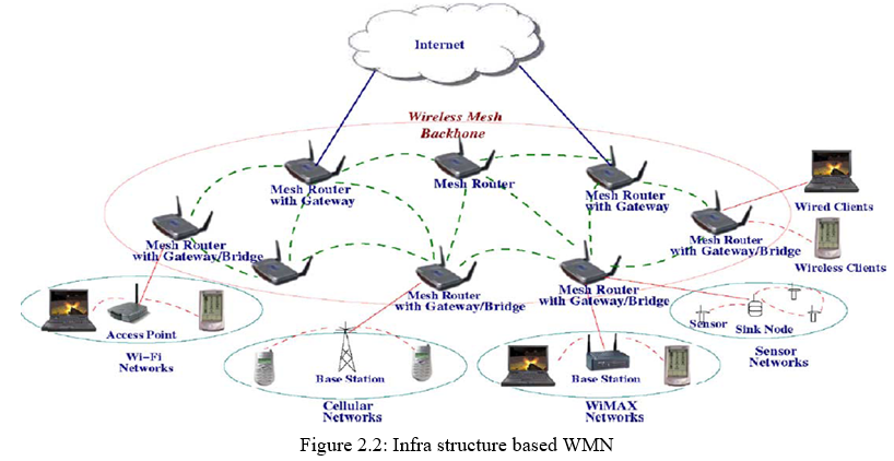
- Infrastructure Based Networks: In this architecture, mesh routers form an infrastructure for clients, where dashed and solid lines indicate wireless and wired links, respectively. The WMN infrastructure/backbone can be built using various types of radio technologies, The mesh routers form a mesh of self-configuring, self-healing links among themselves. With gateway functionality, mesh routers can be connected to the Internet. This approach, also referred to as infrastructure meshing, provides a backbone for conventional clients and enables integration of WMNs with existing wireless networks, through gateway/bridge functionalities in mesh routers. Conventional clients with an Ethernet interface can be connected to mesh routers via Ethernet links. For conventional clients with the same radio technologies as mesh routers, they can directly communicate with mesh routers. If different radio technologies are used, clients must communicate with their base stations that have Ethernet connections to mesh routers. Client WMNs. Client meshing provides peer-to-peer networks among client devices. In this type of architecture, client nodes constitute the actual network to perform routing and configuration functionalities as well as providing end-user applications to customers. Hence, a mesh router is not required for these types of networks. Client WMNs are usually formed using one type of radios on devices. Thus, a Client WMN is actually the same as a conventional ad hoc network. However, the requirements on end-user devices is increased when compared to infrastructure meshing, since in Client WMNs the end-users must perform additional functions such as routing and self-configuration.
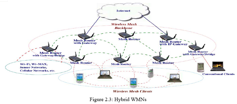
2. Hybrid WMNs: This architecture is the combination of infrastructure and client meshing.. Mesh clients can access the network through mesh routers as well as directly meshing with other mesh clients. While the infrastructure provides connectivity to other networks such as the Internet, Wi-Fi, Wi-MAX, cellular, and sensor networks, the routing capabilities of clients provide improved connectivity and coverage inside WMNs. The characteristics of WMNs are outlined below, where the hybrid architecture is considered for WMNs, since it comprises all the advantages of WMNs
- WMNs support ad hoc networking, and have the capability of self-forming, self-healing, and self-organization.
- WMNs are multi-hop wireless networks, but with a wireless infrastructure/backbone provided by mesh routers.
- Mesh routers have minimal mobility and perform dedicated routing and configuration, which significantly decreases the load of mesh clients and other end nodes.
- Mobility of end nodes is supported easily through the wireless infrastructure.
- Mesh routers integrate heterogeneous networks, including both wired and wireless. Thus, multiple types of network access exist in WMNs.
- Power-consumption constraints are different for mesh routers and mesh clients.
- WMNs are not stand-alone and need to be compatible and interoperable with other wireless networks.
Therefore, WMNs diversify the capabilities of ad-hoc networks instead of simply being another type of ad hoc network. These additional capabilities necessitate new algorithms and design principles for the realization of WMNs.
F. ARS Architecture
- Localized Reconfiguration: Based on multiple channels and radio associations vailable, ARS generates reconfiguration plans that allow for changes of network configurations only in the vicinity where link failures occurred while retaining configurations in areas remote from failure locations.
- Qos-Aware Planning: ARS effectively identifies QoS satisfiable reconfiguration plans by estimating the QoS satisfiability of generated reconfiguration plans and deriving their expected benefits in channel utilization.
- Autonomous Reconfiguration via Link-Quality Monitoring: ARS accurately monitors the quality4 of links of each node in a distributed manner. Furthermore, based on the measurements and given links’ QoS constraints, ARS detects local link failures and autonomously initiates network reconfiguration.
- Cross-Layer Interaction: ARS actively interacts across the network and link layers for planning. This interaction enables ARS to include a rerouting for reconfiguration planning in addition to link-layer reconfiguration. ARS can also maintain connectivity during recovery period with the help of a routing protocol. Algorithm describes the operation of ARS. First, ARS in every mesh node monitors the quality of its outgoing wireless links at every (e.g., 10 s) and reports the results to a gateway via a management message. Second, once it detects a link failure(s), ARS in the detector node(s) triggers the formation of a group among local mesh routers that use a faulty channel, and one of the group members is elected as a leader using the well-known bully algorithm for coordinating the reconfiguration. Third, the leader node sends a planning-request message to a gateway. Then, the gateway synchronizes the planning requests if there are multiple requests and generates a reconfiguration plan for the request. Fourth, the gateway sends a reconfiguration plan to the leader node and the group members. Finally, all nodes in
- Planning For Localized Network Reconfiguration: The group execute the corresponding configuration changes, if any, and resolve the group. We assume that during the formation and reconfiguration, all messages are reliably delivered via a routing protocol and per-hop retransmission timer. The core function of ARS is to systematically generate localized reconfiguration plans. A reconfiguration plan is defined as a set of links’ configuration changes (e.g., channel switch, link association) necessary for a network to recover from a link(s) failure on a channel, and there are usually multiple reconfiguration plans for each link failure. Existing channel-assignment and scheduling algorithms seek “optimal” solutions by considering tight QoS constraints on all links, thus requiring a large configuration space to be searched and hence making the planning often an NP-complete problem . In addition, change in a link’s requirement may lead to completely different network configurations. By contrast, ARS systematically generates reconfiguration plans that localize network changes by dividing the reconfiguration planning into three processes feasibility, QoS satisfiability, and optimality and applying different levels of constraints. ARS first applies connectivity constraints to generate a set of feasible reconfiguration plans that enumerate feasible channel, link, and route changes around the faulty areas, given connectivity and link-failure constraints. Then, within the set, ARS applies strict constraints (i.e.QoS and network utilization) to identify a reconfiguration plan that satisfies the QoS demands and that improves network utilization most.
- Feasible Plan Generation: Generating feasible plans is essentially to search all legitimate changes in links’ configurations and their combinations around the faulty area. Given multiple radios, channels, and routes, ARS identifies feasible changes that help avoid a local link failure but maintain existing network connectivity as much as possible.
- Maintaining Network Connectivity and Utilization: While avoiding the use of the faulty channel, ARS needs to maintain connectivity with the full utilization of radio resources. Because each radio can associate itself with multiple neighbouring nodes, a change in one link triggers other neighboring links to change their settings. To coordinate such propagation, ARS takes a two-step approach. ARS first generates feasible changes of each link using the primitives, and then combines a set of feasible changes that enable a network to maintain its own connectivity. Furthermore, for the combination, ARS maximizes the usage of network resources by making each radio of a mesh node associate itself with at least one link and by avoiding the use of same (redundant) channel among radios in one node.
- Controlling The Scope Of Reconfiguration Changes: ARS has to limit network changes as local as possible, but at the same time it needs to find a locally optimal solution by considering more network changes or scope. To make this trade off, ARS uses a -hop reconfiguration parameter. Starting from a faulty link(s), ARS considers link changes within the first hops and generates feasible plans. If ARS cannot find a local solution, it increases the number of hops so that ARS may explore a broad range of link changes. Thus, the total number of reconfiguration changes is determined on the basis of existing configurations around the faulty area as well as the value.
- Per-Link Bandwidth Estimation: For each feasible plan, ARS has to check whether each link’s configuration change satisfies its bandwidth requirement, so it must estimate link bandwidth. To estimate link bandwidth, ARS accurately measures each link’s capacity and its available channel airtime. In multi-hop wireless networks equipped with a CSMA-like MAC, each link’s achievable bandwidth (or throughput) can be affected by both link capacity and activities of other links that share the channel airtime. Even though numerous bandwidth-estimation techniques have been proposed, they focus on the average bandwidth of each node in a network or the end-to-end throughput of flows , which cannot be used to calculate the impact of per-link configuration changes. By contrast, ARS estimates an individual link’s capacity based on measured (or cached) link-quality information—packet-delivery ratio and data-transmission rate measured by passively monitoring the transmissions of data or probing packets —and the formula derived in the Appendix. Here, we assume that ARS is assumed to cache link-quality information for other channels and use the cached information to generate reconfiguration plans. If the information becomes obsolete, ARS detects link failures and triggers another reconfiguration to find QoS-satisfiable plans—lazy monitoring.
- Examining Per-Link Bandwidth Satisfiability: Given measured bandwidth and bandwidth requirements, ARS has to check if the new link change(s) satisfies QoS requirements. ARS defines and uses the expected busy airtime ratio of each link to check the link’s QoS satisfiability. Assuming that a link’s bandwidth requirement is given, the link’s busy airtime ratio (BAR) can be defined as and must not exceed 1.0 (i.e., ) for a link to satisfy its bandwidth requirement. If multiple links share the airtime of one channel, ARS calculates aggregate BAR of end-radios of a link, which is defined as , where is a radio ID, a link associated with radio , and the set of directed links within and across radio ’s transmission range.
- Breaking A Tie Among Multiple Plans: Multiple reconfiguration plans can have the same benefit, and ARS needs to break a tie among them. ARS uses the number of link changes that each plan requires to break a tie although link configuration changes incur a small amount of flow disruption (e.g in the order of 10 ms), the less changes in link configuration, and the less network disruption.
G. Routing Layer
Despite the availability of many routing protocols for ad hoc networks, the design of routing protocols for WMNs is still an active research area. We believe that an optimal routing protocol for WMNs must capture the following features:
- Multiple Performance Metrics: Many existing routing protocols use minimum hop-count as a performance metric to select the routing path. This has been demonstrated to be ineffective in many situations.
- Scalability: Setting up or maintaining a routing path in a very large wireless network may take a long time. Thus, it is critical to have a scalable routing protocol in WMNs.
- Robustness: To avoid service disruption, WMNs must be robust to link failures or congestion. Routing protocols also need to perform load balancing.
- Efficient Routing with Mesh Infrastructure: Considering the minimal mobility and no constraints on power consumption in mesh routers, the routing protocol in mesh routers is expected to be much simpler than ad hoc network routing protocols. With the mesh infrastructure provided by mesh routers, the routing protocol for mesh clients can also be made simple. Existing routing protocols for ad hoc networks have already considered some of these features. However, none of them has captured all of these features, as explained in the following routing protocols.
- Routing Protocols with Various Performance Metrics: The impact of performance metrics on a routing protocol is studied where link quality source routing (LQSR) selects a routing path according to link quality metrics. Three performance metrics, i.e., expected transmission count (ETX), per-hop RTT, and per-hop packet pair, are implemented separately. The performance of the routing protocol with these three performance metrics is compared with the method using the minimum hop-count. For stationary nodes in WMNs, ETX achieves the best performance, while the minimum hopcount method outperforms the three link quality metrics when nodes are mobile. This result illustrates that the link quality metrics are used still not enough for WMNs when mobility is concerned.
- Multi-Radio Routing: A multi-radio LQSR (MR-LQSR) is proposed , where a new performance metric, called weighted cumulative expected transmission time (WCETT), is incorporated. WCETT takes into account both link quality metric and the minimum hop-count and achieves good tradeoff between delay and throughput. MR-LQSR assumes that all radios on each node are tuned to non-interfering channels with the assignment changing infrequently.
- Multi-Path Routing: The main objectives of using multi-path routing are to perform better load balancing and to provide high fault tolerance. Multiple paths are selected between source and destination. When a link is broken on a path due to a bad channel quality or mobility, another path in the set of existing paths can be chosen. Thus, without waiting to set up a new routing path, the end-to-end delay, throughput, and fault tolerance can be improved. However, given a performance metric, the improvement depends on the availability of node disjoint routes between source and destination. Another drawback of multi-path routing is its complexity.
- Hierarchical Routing: In hierarchical routing , a certain self-organization scheme is employed to group network nodes into clusters. Each cluster has one or more cluster heads. Nodes in a cluster can be one or more hops away from the cluster head. Since connectivity between clusters is needed, some nodes can communicate with more than one cluster and work as a gateway. When the node density is high, hierarchical routing protocols tend to achieve much better performance because of less overhead, shorter average routing path, and quicker set-up procedure of routing path. However, the complexity of maintaining the hierarchy may compromise the performance of the routing protocol. Moreover, in WMNs, a mesh client must avoid being a cluster head because it can become a bottleneck due to its limited capability.
- Geographic Routing: Compared to topology-based routing schemes, geographic routing schemes forward packets by only using the position information of nodes in the vicinity and the destination node . Thus, topology change has less impact on the geographic routing than the other routing protocols. Early geographic routing algorithms are a type of single-path greedy routing schemes in which the packet forwarding decision is made based on the location information of the current forwarding node, its neighbors, and the destination node. However, all greedy routing algorithms have a common problem, i.e., delivery is not guaranteed even if a path exists between source and destination. In order to guarantee delivery, planar-graph-based geographic routing algorithms have been proposed recently. However, these algorithms usually have much higher communication overhead than the single- path greedy routing algorithms.
H. Network Management
Many management functions are needed to maintain the appropriate operation of WMNs.
- Mobility Management: A distributed mobility management scheme is needed for WMNs. However, because of the existence of a backbone network, a distributed scheme for WMNs can be simpler than that for mobile ad hoc networks. How to take advantage of the network backbone to design a lightweight distributed mobility management scheme for WMNs needs further investigation. Mobility management is closely related to multiple layers of network protocols, so developing multi-layer mobility management schemes is another interesting research topic. Location service is a desired feature by WMNs. Location information can enhance the performance of MAC and routing protocols, and it can help to develop promising location related applications. Proposing accurate or efficient algorithms for location service is still an open research topic.
- Power Management: The goal of power management in WMNs varies with network nodes. Usually, mesh routers do not have a constraint on power consumption; power management aims to control connectivity, interference, spectrum spatial- reuse, and topology. In contrast to mesh routers, mesh clients may expect protocols to be power-efficient. Thus, it is quite possible that WMNs require power management to optimize both power efficiency and connectivity, which results in a complicated problem.
- Network Monitoring: Many functions are performed in a network management protocol. The statistics in the management information base (MIB) of mesh nodes especially mesh routers; need to be reported to one or several servers in order to continuously monitor network performance. In addition, data processing algorithms in the performance monitoring software on the server analyze these statistical data and determine potential abnormalities. Based on the statistical information collected from the MIB, data processing algorithms can also accomplish many other functions such as network topology monitoring. Several research issues exist in network monitoring. To reduce overhead, efficient transmission of network monitoring information in a mesh network topology is expected. In addition, in order to accurately detect abnormal operation and quickly derive a multi-hop mesh network topology of WMNs, new data processing algorithms need to be developed.
I. Dynamic Path Maintenance
The required QoS is ensured during the time when an established path remains unbroken. The QoS provision, however, is disrupted during the rerouting time. We want to be restrictive on the type of networks studied in this paper. Our routing algorithm works well when the average life time of an established path is much longer (such as an order of magnitude longer) than the average rerouting time. In such a case, the required QoS is ensured in most of the connection’s lifetime. There are numerous examples of such mobile networks. For instance, a group of soldiers stays in their bunkers and communicates with each other; a group of warships moves into a formation in which the relative positions of the ships are maintained. In this paper, we shall only consider the type of networks whose topologies are relatively stable because our routing-rerouting architecture does not support ad hoc networks with violently changing topologies.
- Rerouting: Rerouting is commonly used to deal with the problem of path breaking in ad hoc networks. When a node detects a broken path, it looks up in the connection table to find the source node of the connection and then sends a path-breaking message. When receives the message, it activates the ticket-based routing algorithm and reroutes the connection to another feasible path. Meanwhile, a resource releasing message is sent along the original path to release the reserved resources. Since the path has been broken, some intermediate nodes will not receive the resource-releasing message. However, that will not cause the resources to be held indefinitely because resource reservation is part of the soft state that will be deleted automatically if not refreshed . In the process of rerouting, data packets are transmitted as best-effort traffic, which means the required QoS is not guaranteed during this period of time. Although the rerouting takes only a message round trip time to reestablish the connection along a new feasible path, we want to reduce the jitter in the QoS provision as much as possible. The common approach to tolerate the fault condition (broken paths) is to introduce redundancy .
- Path Redundancy: We consider a broken path as a fault and use the path redundancy for fault-tolerance. There is a tradeoff between the overhead of redundancy and the performance of QoS provision. We propose a multilevel redundancy scheme to meet the diversity of user requirements.
- First-Level Redundancy: For the most critical connections, the highest level of redundancy is used. The idea is to establish multiple routing paths for the same connection. Every data packet is sent along each path independently. If the destination receives the same packet from more than one path, it keeps the first copy and discards the rest. The required QoS is guaranteed as long as any of the paths remain unbroken. Recall that our ticket-based routing algorithms may detect multiple feasible paths in a single run. Increasing the number of tickets will improve the chance of finding multiple feasible paths. The number of routing paths actually established depends on the redundancy requirement and the overhead concern. Disjointed paths are preferred because multiple paths will be broken when a shared link is broken. Multiple consecutive runs of the routing algorithm help to establish the disjointed routing paths; the successive runs use only the links that are not on the paths established by the previous runs.
- Second-Level Redundancy: For the ordinary connections that allow certain degree of QoS disruption, the second level redundancy is used. It is similar to the first level redundancy, except that, among the multiple established paths, one is selected as the primary path, and the others are secondary paths. Data packets are sent only along the primary path. Although resources are reserved on the secondary paths as well, they are not used. The resources held on the secondary path will not be wasted because they will be used by the best effort traffic in a work-conserving system. When the primary path is detected broken, the source node selects one from the secondary paths to be the new primary path. When becomes less than , the routing algorithm is activated to find more secondary paths.
- Third-Level Redundancy: The ordinary connections may also use the third level redundancy, which has the lowest overhead. It is similar to the second level redundancy except that no resource is reserved on the secondary paths. When the primary path is broken, control messages are sent along the secondary paths to check the current resource availability. If some of the secondary paths remain feasible, one is selected as the new primary path, and the resources are reserved. If none of them is feasible, rerouting is activated.
3. Path Repairing: Dynamic path-repairing repairs the routing path at the breaking point, shifts the data traffic to a neighbor node, and reconfigures the path around the breaking point without rerouting the connection along a completely new path. The routing path is broken after moves out of the transmission range of, Instead of sending a path-breaking message to the source, tries to repair the path by broadcasting a repair-requesting message to the current neighbors asking if any of them are able to take over the job of, upon receipt of the message, the neighbors that have links to reply their resource availabilities to, Based on the received information, finds that has sufficient resources for that role. It adds link to the routing path and then sends a path-repairing message to upon receipt of the path repairing message, reserves the required resources and adds link to the routing path. In order to do path repairing, the connection table at must be extended to store the successive node’s successive node. The repair requesting message sent by to its neighbors contains. Every neighbor sends back a reply message, including at least a Boolean field telling whether it has a link to , If it does, the message also contains bandwidth (or delay), in addition to other information such as cost . In the case of bandwidth-constrained routing, when receives a reply message from a neighbor node, it checks whether both bandwidth and bandwidth are satisfied, where is the bandwidth requirement. If so, sends a path-repairing message to in order to reestablish the broken routing path through, If multiple neighbors satisfy the requirement, the one which minimizes cost is selected. If none of the neighbors satisfies the requirement, a path-breaking message is sent to the source for rerouting.
III. SYSTEM ANALYSIS, DESIGN AND DEVOLOPMENT
A. Existing System
WIRELESS mesh networks (WMNs) are being developed actively and deployed widely for a variety of applications, such as public safety, environment monitoring, and citywide wireless Internet services. They have also been evolving in various forms (e.g., using multi radio/channel systems to meet the increasing capacity demands by the above-mentioned and other emerging applications.
- Limitations Of Existing System: First, resource-allocation algorithms can provide (theoretical) guidelines for initial network resource planning. However, even though their approach provides a comprehensive and optimal network configuration plan, they often require “global” configuration changes, which are undesirable in case of frequent local link failures. Next, a greedy channel-assignment algorithm can reduce the requirement of network changes by changing settings of only the faulty link(s). However, this greedy change might not be able to realize full improvements, which can only be achieved by considering configurations of neighboring mesh routers in addition to the faulty link(s). Third, fault-tolerant routing protocols, such as local rerouting or multipath routing, can be adopted to use network-level path diversity for avoiding the faulty links. However, they rely on detour paths or redundant transmissions, which may require more network resources than link-level network reconfiguration
- Proposed System: This paper presented an autonomous network reconfiguration system (ARS) that enables a multi radio WMN to autonomously recover from wireless link failures. ARS generates an effective reconfiguration plan that requires only local network configuration changes by exploiting channel, radio, and path diversity. ARS effectively identifies reconfiguration plans that satisfy applications’ QoS constraints, admitting up to two times more flows than static assignment, through QoS aware planning. Next, ARS’s online re configurability allows for real-time failure detection and network reconfiguration, thus improving channel efficiency by 92%. Our experimental evaluation on a Linux-based implementation and ns2-based simulation have demonstrated the effectiveness of ARS in recovering from local link-failures and in satisfying applications’ diverse QoS demands.
B. System Design and Development
- Fact Finding
Fact Finding is the methods of gathering the information required about the existing system. Some of them are as follows.
- Observation
- Record Searching
- Special purpose Records
- Sampling
- Questionnaires
- Interviewing
Observation of the current work situation will provide clues to problems and atmosphere.
Record searching, special purpose records and sampling will give quantitative information about the system which facilitates sizing of the proposed system and may also point the areas of difficulties which are being experienced.
Questionnaires can be used to collect the quantifiable data about the system. All of the techniques need to be supplemented by more detailed discussion of the interview situation. The identification of the user requirements, decision areas, objectives. And responsibilities for certain procedures can only be achieved for interviewing.
Based on the above fact finding techniques, it is observed the current situation of the existing system. It is very helpful to finding the areas of difficulties, which are being experienced in the existing system. Thus it helps to develop the proposed system with the quantifiable data.
2. Input Design
Input Design is part of overall system design, which requires very careful attention. If the data going into the system is incorrect then the processing and output will magnify these errors.
The inputs in the system are of three types:
- External: Which are prime inputs for the system
- Internal: Which are user communication with the system
- Interactive: Which are inputs entered during a dialog with the computer
The above input types enrich the proposed system with numerous facilities that make it more advantageous in comparison with the exiting normal system. All the inputs entered are completely raw, initially, before being entered into a database, each of them available processing. The input format in this system has been designed with the following objectives in mind.
C. Feasibility Analysis
All projects are feasible, given unlimited resources and infinite time. Before going further in to the steps of software development, the system analyst has to analyze whether the proposed system will be feasible for the organization and must identify the customer needs. The main purpose of feasibility study is to determine whether the problem is worth solving. The success of a system is also lies in the amount of feasibility study done on it. Many feasibility studies have to be done on any system. But there are three main feasibility tests to be performed.
They are
- Operational Feasibility: During feasibility analysis operational feasibility study is a must. This is because; according to software engineering principles operational feasibility or in other words usability should be very high. A thorough analysis is done and found that the system is operational.
- Technical Feasibility: System analyst to check the technical feasibility of proposed system. Taking account of the hardware it is used for the system development, data storage, processing and output, makes the technical feasibility assessment. The system analyst has to check whether the company or user who is implementing the system has enough resource available for the smooth running of the application. Actually the requirements for this application is very less and thus it is technically feasible.
- Economical Feasibility: Before going further in to the development of the proposed system.The system analyst has to check the economic feasibility of the proposed system and the cost for running the system is composed with the cost benefit that can achieve by implementing the system. As in the case of Crypto Media development cost is not high, as it doesn’t need any extra hardware and software. Thus the system is economically feasible.
System design is process of planning a new system to document or altogether replace the old system. The purpose of the design phase is to plan a solution for the problem. The phase is the first step in moving from the problem domain to the solution domain. The design of the system is the critical aspect that affects the quality of the software. System design is also called top-level design. The design phase translates the logical aspects of the system into physical aspects of the system.
IV. PROJECT DESCRIPTION
Wireless mesh networks have the potential to deliver Internet broadband access, wireless local area network coverage and network connectivity for stationary or mobile hosts at low costs both for network operators and customers. The core technology involves a network of wireless routers relaying each others’ packets in a multihop fashion. Many variations on targeted applications and implementation choices offer different opportunities to emerging companies in this emerging area.
These independent wireless mesh networks bring many advantages to challenging outdoor communications environments that have traditionally been difficult to cover. Quick and easy to install over a wide geographic area while offering the flexibility to be deployed in any outdoor location, wireless mesh networks are an ideal communications solution for public safety, construction, transportation, mining and other industrial applications.
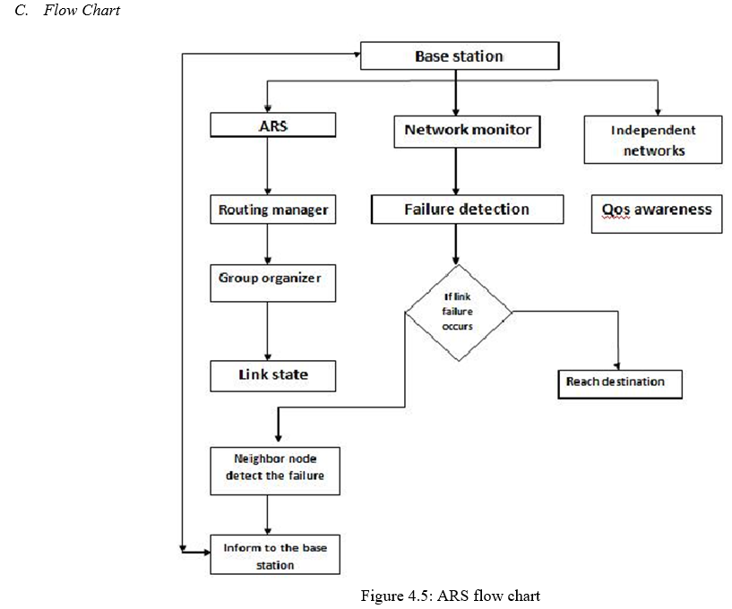
A. Modules
- Route discovery
- Link-Failure Detection
- Route recovery
- Reconfiguration system
- Route Discovery
a. AODV initiates a route discovery process using Route Request (RREQ) and Route Reply (RREP).
b. The source node will create a RREQ packet
c. The broadcast ID is incremented each time the source node initiates RREQ.
d. The requests are sent using RREQ message and the information in connection with creation of a route is sent back in RREP message.
e. The source node broadcasts the RREQ packet to its neighbors’ and then sets a timer to wait for a reply
f. Basically, a lifetime is associated with the reverse route entry and if this entry is not used within this lifetime, the route information is deleted.
g. If the RREQ is lost during transmission, the source node is allowed to broadcast again using route discovery mechanism.
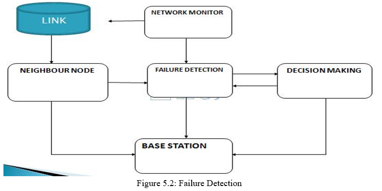
2. Link-Failure Detection: ARS in every mesh node monitors the quality of its outgoing wireless links at every tm (e.g., 10 sec) and reports the results to a gateway via a management message. Second, once it detects a link failure(s), ARS in the detector node(s) triggers the formation of a group among local mesh routers that use a faulty channel, and one of the group members is elected as a leader and coordinating the reconfiguration.
Three types of failures:
a. Self failure
b. Path failure
c. Link failure
In self failure, the node itself has failed due to a crash, re-boot, bug in software code, or connectivity issue. In path failure, a node along the path fails, causing other nodes to fail or there are collisions along the path. In sink (i.e., base station) failure, the whole network appears to be failing when it is the sink that has failed. Failure at the sink may be due to bad sink placement, changes in the environment after deployment, and connectivity issues.
Automated link failure and Interference Detection Avoidance (AIDA) module determines when it is advantageous to change channels for any AP or backhaul radio that experiences high levels of RF interference. The AIDA module monitors all channels, including unused channels, in order to perform this service.
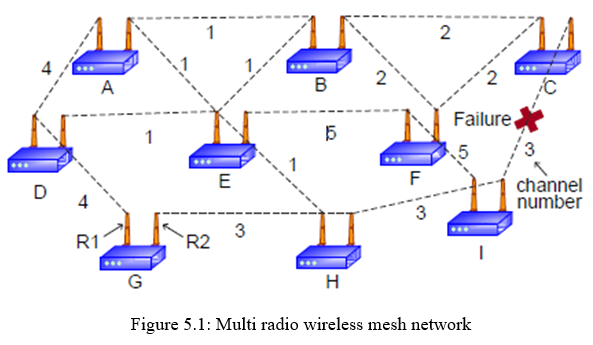
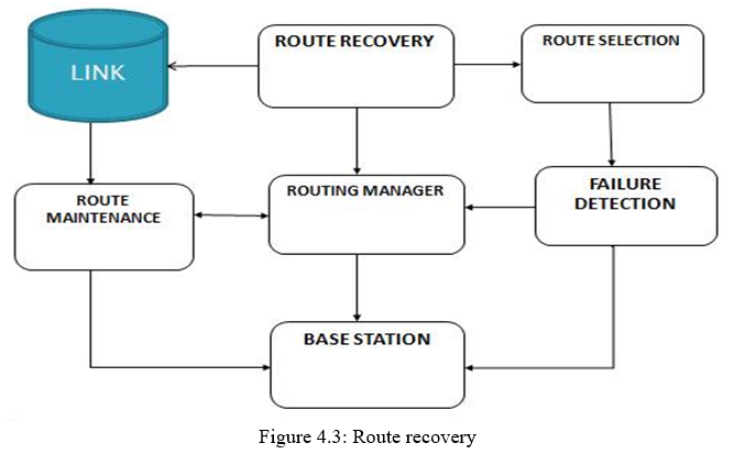
3. Route Recovery: A network is assumed to consist of mesh nodes, IEEE 802.11-based wireless links, and one control gateway. Each mesh node is equipped with n radios, and each radio’s channel and link assignments are initially made by using global channel/link assignment algorithms.
a. Route recovery scheme in ad hoc networks to reduce the time delay and control overhead in the route recovery process.
b. Maintaining connectivity with the sink node is a crucial issue to collect data from sensors without any interruption. While sensors are typically deployed in abundance to tolerate possible node failures, a large number of such failures within the same region simultaneously may result in losing the connectivity with the sink node which eventually reduces the quality and efficiency of the network operation.
c. The idea of this distributed heuristic is based on maintaining the route information at each node to the sink and then utilizing such information for the relocation of the sensors.
d. Route recovery scheme to solve the link failure problem caused by node movement, packet collision or bad channel condition. Since it considers a backup node mobility and conduct route recovery implicitly, it can support fast route recovery and then provide reliable and stable route for routing protocols.
4. Leader Node: The leader node sends a planning-request message to a gateway. If any link is failure group members send request to the particular leader after that the leader node send request to the gateway.
5. Network Planner: It generates reconfiguration plans only in a gateway node. Network planner plans the diversity path for avoiding the faulty links. Then, the gateway synchronizes the planning requests—if there are multiples requests—and generates a reconfiguration plan for the request. Fourth, the gateway sends a reconfiguration plan to the leader node and the group members. Finally, all nodes in the group execute the corresponding configuration changes, if any, and resolve the group.
6. Autonomous Reconfiguration System: A reconfiguration plan is defined as a set of links’ configuration changes necessary for a network to recover from a link failure on a channel, and there are usually multiple reconfiguration plans for each link failure. ARS systematically generates reconfiguration plans that localize network changes by dividing the reconfiguration planning into three processes feasibility, QoS satisfiability, and optimality—and applying different levels of constraints. ARS first applies connectivity constraints to generate a set of feasible reconfiguration plans that enumerate feasible channel, link, and route changes around the faulty areas, given connectivity and link-failure constraints. Then, within the set, ARS applies strict constraints (i.e., QoS and network utilization) to identify a reconfiguration plan that satisfies the QoS demands and that improves network utilization most.
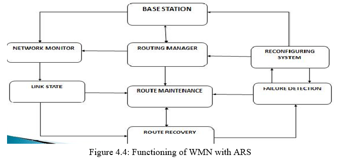
B. Wireless Mesh Networks with ARS System
WIRELESS mesh networks (WMNs) are being developed actively and deployed widely for a variety of applications, such as public safety, environment monitoring, and citywide wireless Internet services. First, resource-allocation algorithms can provide (theoretical) guidelines for initial network resource planning. However, even though their approach provides a comprehensive and optimal network configuration plan, they often require “global” configuration changes, which are undesirable in case of frequent local link failures. Next, a greedy channel-assignment algorithm can reduce the requirement of network changes by changing settings of only the faulty link(s). However, this greedy change might not be able to realize full improvements, which can only be achieved by considering configurations of neighbouring mesh routers in addition to the faulty link(s). Third, fault-tolerant routing protocols, such as local rerouting or multipath routing, can be adopted to use network-level path diversity for avoiding the faulty links. However, they rely on detour paths or redundant transmissions, which may require more network resources than link-level network reconfiguration. To overcome the above limitations, we propose an autonomous network reconfiguration system (ARS) that allows a multi-radio WMN to autonomously reconfigure its local network settings—channel, radio, and route assignment— for real-time recovery from link failures. In its core, ARS is equipped with a reconfiguration planning algorithm that identifies local configuration changes for the recovery while minimizing changes of healthy network settings. Briefly, ARS first searches for feasible local configuration changes available around a faulty area, based on current channel and radio associations. Then, by imposing current network settings as constraints, ARS identifies reconfiguration plans that require the minimum number of changes for the healthy network settings. ARS also includes a monitoring protocol that enables a WMN to perform real-time failure recovery in conjunction with the planning algorithm. The accurate link-quality information from the monitoring protocol is used to identify network changes that satisfy applications’ new QoS demands or that avoid propagation of QoS failures to neighbouring links (or “ripple effects”). Running in every mesh node, the monitoring protocol periodically measures wireless link conditions via a hybrid link-quality measurement technique,. Based on the measurement information, ARS detects link failures and/or generates QoS-aware network reconfiguration plans upon detection of a link failure.
D. Complexity of ARS
ARS incurs reasonable bandwidth and computation overheads. First, the network monitoring part in the reconfiguration protocols is made highly efficient by exploiting existing data traffic and consumes less than 12 kb/s probing bandwidth (i.e., one packet per second) for each radio. In addition, the group formation requires only message overhead (in forming a spanning tree), where the number of nodes in the group. Next, the computational overhead in ARS mainly stems from the planning algorithms. Specifically, generating its possible link plans incurs complexity, where the number of available channels and the number of radios. Next, a gateway node needs to generate and evaluate feasible plans, which incurs search overhead in a constraint graph that consists of nodes, where the number of links that use a faulty channel in the group.
V. SOFTWARE REQUIREMENTS AND FEATURES
A. Software Requirements
Tools: Network Simulator version-2
Os : Linux
- 2 Languages
Front End : TCL (Tool Command Language)
Back End : C++
1.3 Technology Used
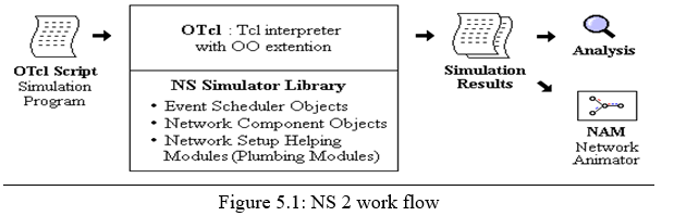
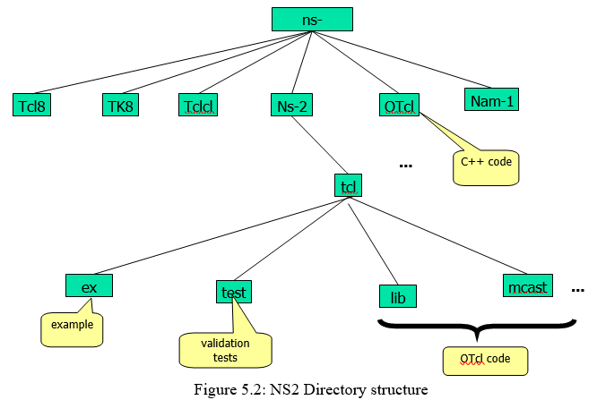
Network Simulator-2
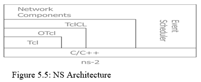
B. NS Features
? NS is an object oriented discrete event simulator
– Simulator maintains list of events and executes one event after another
– Single thread of control: no locking or race conditions
? Back end is C++ event scheduler
– Protocols mostly
– Fast to run, more control
? Front end is OTCL
– Creating scenarios, extensions to C++ protocols
– Fast to write and change
C. NS Programming Structure
- Create the event scheduler
- Turn on tracing
- Create network topology
- Create transport connections
- Generate traffic
- Insert errors
7. Event Scheduler
In this Event scheduler while we processing many data’s at a time it will process one by one (i.e.) FIFO concept, so there is no congestion while transferring the packets.
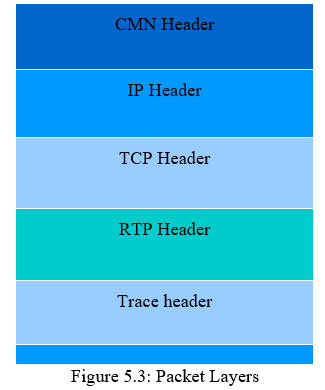
8. Packets
It is the collection of data, whether header is called or not all header files where present in the stack registers.
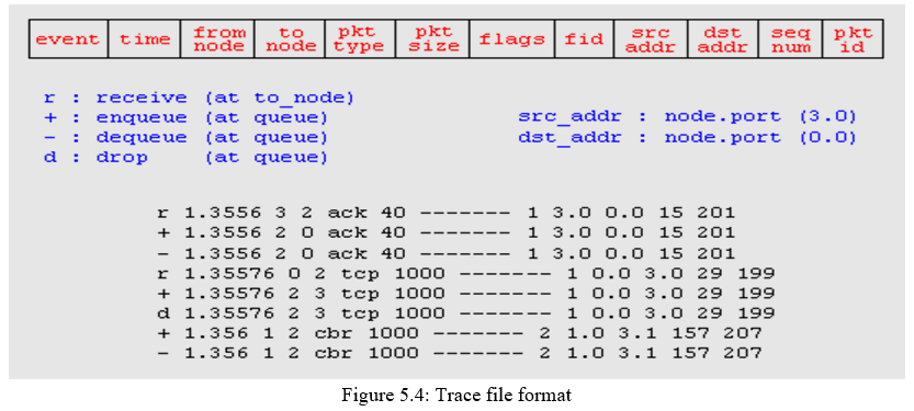
9. Turn On Tracing
Trace packets on individual link Trace file format
10. Create Network Topology (Physical Layer)
The Physical Layer is the first and lowest layer in the seven-layer OSI model of computer networking. The implementation of this layer is often termed PHY. The Physical Layer consists of the basic hardware transmission technologies of a network. It is a fundamental layer underlying the logical data structures of the higher level functions in a network. Due to the plethora of available hardware technologies with widely varying characteristics, this is perhaps the most complex layer in the OSI architecture.
The Physical Layer defines the means of transmitting raw bits rather than logical data packets over a physical link connecting networking nodes. The bit stream may be grouped into code words or symbols and converted to a physical that is transmitted over hardware.
11. Transport Connection (Transport Layer)
Transport layers are contained in both the TCP/IP which is the foundation of the INTERNET and the OSI model of general networking. The definitions of the Transport Layer are slightly different in these two models. This article primarily refers to the TCP/IP model, in which TCP is largely for a convenient application programming interface to internet hosts, as opposed to the OSI model of definition interface. The most well-known transport protocol is the (TCP). It lent its name to the title of the entire internet protocol suite TCP/IP. It is used for connection-oriented transmissions, whereas the connectionless user datagram suite (UDP) is used for simpler messaging transmissions. TCP is the more complex protocol, due to its stateful design incorporating reliable transmission and data stream services.
12. Generate Traffic (Application Layer)
In TCP/IP, the Application Layer contains all protocols and methods that fall into the realm of process-to-process communications via an Internet Protocol (IP) network using the Transport layer protocols to establish underlying host-to-host connections.
In the OSI model, the definition of its Application Layer is narrower in scope, explicitly distinguishing additional functionality above the Transport Layer at two additional levels: session layer and presentation layer OSI specifies strict modular separation of functionality at these layers and provides protocol for each layer.
13. Insert Errors
Start debugging of errors
D. Creating the Topology
#create a new simulator object
set ns [new Simulator]
#open the nam trace file
set nf [open out.nam w]
$ns namtrace-all $nf
#define a 'finish' procedure
proc finish {} {
global ns nf
$ns flush-trace
#close the trace file
close $nf
#execute nam on the trace file
exec nam out.nam &
exit 0
}
E. Motivation for Simulations
- Cheap does not require costly equipment
- Complex scenarios can be easily tested
- Results can be quickly obtained more ideas can be tested in a smaller timeframe
- The real thing isn't yet available
- Controlled experimental conditions Repeatability helps aid debugging
- Disadvantages: Real systems too complex to model
VI. SYSTEM TESTING AND OUTPUT DESIGN
A. Black Box Testing
Black box testing also called behavioural testing focuses on the functional requirements of the software. That is black box testing enables the software engineer to derive sets of input conditions that will fully exercise all functional requirements for a program. Black box testing attempts to find errors in the following categories. Incorrect or missing functions. Interface errors. Errors in data structures or external data base access Behaviour or performance errors. Initialization and termination errors.
Functional Testing and black box type testing geared to functional requirements of an application. This type of testing should be done by testers. Our project does the functional testing of what input given and what output should be obtained.
System Testing-black box type testing that is based on overall requirements specifications; covers all combined parts of a system. The system testing to be done here is that to check with all the peripherals used in the project.
Stress Testing-term often used interchangeably with ‘load’ and ‘performance’ testing. Also used to describe such tests as system functional testing while under unusually heavy loads, heavy repletion of certain actions or inputs, input of large numerical values.
Performance Testing-term often used interchangeably with ‘stresses’ and ‘load’ testing. Ideally ‘performance’ testing is defined in requirements documentation or QA or Test Plans.
B. White Box Testing
White box testing sometimes called glass box testing is a test case design method that uses the control structure of the procedural design to derive test cases. Using white box testing methods, the software engineer can derive test cases that guarantee that all independent paths within a module have been exercised at least once. Exercise all logical decisions on their true and false sides. Execute all loops at their boundaries and within their operational bounds. Exercise internal data structures to ensure their validity
C. Unit Testing
The most ‘micro’ scale of testing to test particular functions or code modules. Typically, it is done by the programmer and not by tester, as it requires detailed knowledge of the internal program design and code. Not always easily done unless the application has a well designed architecture with tight code; may require developing test modules or test harnesses.
D. Quality Assurance
Software Quality Assurance involves the entire software development process-monitoring and improving the process, making sure that any agreed-upon standards and procedures are followed, and ensuring that problems are found and dealt with. It is oriented to ‘prevention’.
E. Software Life Cycle
The life cycle begins when an application is first conceived and ends when it is no longer in use. It includes aspects such as initial concept, requirements analysis, functional design, internal design, documentation planning, test planning, coding, document preparation, integration, testing, maintenance, updates, retesting, phase-out, and other aspects.
F. Verification and Validation
Verification refers to the set of activities that ensure that software correctly implements a specific function. Validation refers to a different set of activities that ensures that the software has been built is traceable to customer requirements.
Verification and validation encompasses a wide array of SQA activities that include formal technical reviews, quality and configuration audits, performance monitoring, simulation, feasibility study, documentation review, database review, algorithm analysis, development testing, qualification testing and installation testing.
G. System Implementation
System implementation is a stage in a stage in the project where the where the theoretical designs turned into working system.The most crucial stage the user confidence that the new system will work effectively and efficiently.
The performance of reliability of the system was tested and it gained acceptance. The system was implemented successfully. Implementation is a process that means converting a new system into operation.
Proper implementation is essential to provide a reliable system to meet organization requirements. During the implementation stage a live demon was undertaken and and made in front of end-users.
Implementation is a stage of project when the system design is turned into a working system. The stage consists of the following steps.
- Testing the developed program with sample data.
- Detection and correction of internal error.
- Testing the system to meet the user requirement.
- Feeding the real time data and retesting.
- Making necessary change as described by the use
H. Output Design
Intelligent output design will improve systems relationships with the user and help in decision making. Outputs are also used to provide a permanent hardcopy of the results for latter consultations. The most important reason, which tempts the user to go for a new system is the output. The output generated by the system is often regarded as the criterion for evaluating the usefulness for the system. Here the output requirements use to be predetermined before going to the actual system design.
The output design is based on the following:
- Determining the various outputs to be presented to the user.
- Differentiating between inputs to be displayed and those to be printed.
- The format for the presentation of the outputs.
I. Critical Design Factors
Increase capacity and flexibility of wireless systems in recent years. Typical examples include directional and smart antennas, multiple input multiple output (MIMO) systems, and multi-radio/multi-channel systems. To further improve the performance of a wireless radio and control by higher layer protocols, more advanced radio technologies, such as reconfigurable radios, frequency agile/cognitive radios, and even software radios, have been used for wireless communication. Although these radio technologies are still in their infancy, they are expected to be the future platform for wireless networks due to their dynamic control capability. These advanced wireless radio technologies all require a revolutionary design in higher-layer protocols, especially MAC and routing protocols. Scalability. Scalability is a critical requirement of WMNs. Without support of this feature, the network performance degrades significantly as the network size increases. For example, routing protocols may not be able to find a reliable routing path, transport protocols may lose connections, and MAC protocols may experience significant throughput reduction. To ensure the scalability in WMNs, all protocols from the MAC layer to the application layer need to be scalable. Mesh Connectivity. Many advantages of WMNs originate from mesh connectivity. To ensure reliable mesh connectivity, network self-organization and topology control algorithms are needed.
Topology-aware MAC and routing protocols can significantly improve the performance of WMNs. Broadband and QoS. Different from classical ad hoc networks, most applications of WMNs are broadband services with heterogeneous QoS requirements. Thus, in addition to end-to-end transmission delay and fairness, more performance metrics, such as delay jitter, aggregate and per-node through- put, and packet loss ratios, must be considered by communication protocols.
Security. Although many security schemes have been proposed for wireless LANs in recent years, they are still not fully applicable for WMNs. For instance, there is no centralized trusted authority to distribute a public key in a WMN due to the distributed system architecture.
The existing security schemes proposed for ad hoc networks can be adopted for WMNs. However, most of the security solutions for ad hoc networks are still not mature enough to be implemented practically. Moreover, the different network architectures between WMNs and ad hoc networks usually render a solution for ad hoc networks ineffective in WMNs. Ease of Use. Protocols must be designed to enable the network to be as autonomous as possible. In addition, network management tools need to be developed to efficiently maintain the operation, monitor the performance, and configure the parameters of WMNs. These tools, together with the autonomous mechanisms in networking protocols, enable rapid deployment of WMNs. Compatibility and Inter-operability. In WMNs it is a default requirement to support network access for both conventional and mesh clients. Therefore, WMNs need to be backward compatible with conventional client nodes. This demands that mesh routers need to be capable of integrating heterogeneous wireless networks.
J. Simulation Models and Methods
ns-2 is used in our simulation study. Throughout the simulation, we use a grid topology with 25 nodes in an area of 1 x1 km .In the topology, adjacent nodes are separated by 180 m, and each node is equipped with a different number of radios, depending on its proximity to a gateway. The gateway is equipped with four radios, one-hop away nodes from a gateway have three radios, and other nodes have two radios. For each node in this topology, we use the following network protocol stacks. First, the shadowing propagation model is used to simulate varying channel quality and multipath effects. Next, CMU 802.11 wireless extension is used for the MAC protocol with a fixed data rate (i.e., 11 Mb/s) and is further modified to support multiple radios and multiple channels. Finally, a link-state routing protocol, a modification of DSDV, and multi radio-aware routing metric (WCETT ) are implemented and used for routing. In these settings, ARS is implemented as an agent in both the MAC layer and a routing protocol as explained in earlier chapters. It periodically collects channel information from MAC and requests channel switching or link-association changes based on its decision. At the same time, it informs the routing protocol of network failures or a routing table update.
K. Simulation Results
For the purpose of performance analysis, NAM trace files are written and graphs are plotted using XGRAPH. The simulator can produce both the visualization trace (Nam) as well as an ASCII file trace corresponding to the events registered at the network. In the trace file the number of packets sent, received and lost is noted down.
Graphs are drawn to compare the performance of the existing system with that of proposed one. The throughput, packet delivery ratio, average end-to-end delay and total dropped packets are calculated based on the parameters from the trace file.
Impact of the reconfiguration range is evaluated. As we increase the hop count from a faulty links, the capacity improvement achieved by the reconfiguration plans is measured. In addition, capacity gain plans that satisfy applications’ QoS constraints are calculated, admitting up to two times more flows than static assignment, through QoS aware planning. Next, ARS’s online reconfigurability allows for real-time failure detection and network reconfiguration, thus improving channel efficiency by 92% and improves network throughput and channel efficiency by more than 26%. Our experimental evaluation on a Linux-based implementation and ns2-based simulation have demonstrated the effectiveness of ARS in recovering from local link-failures and in satisfying applications’ diverse QoS demands.
L. Output NAM Window
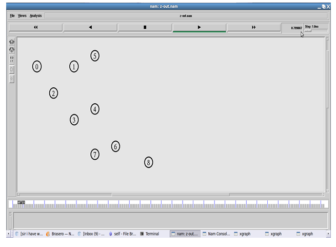
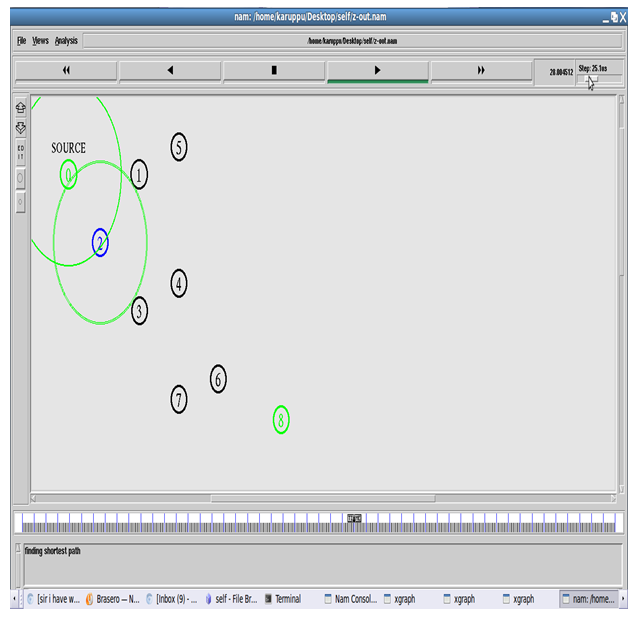
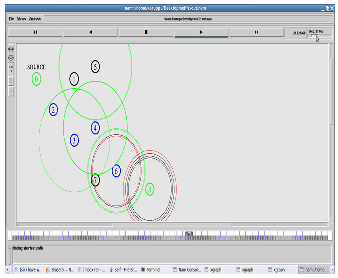
2. Finding shortest path
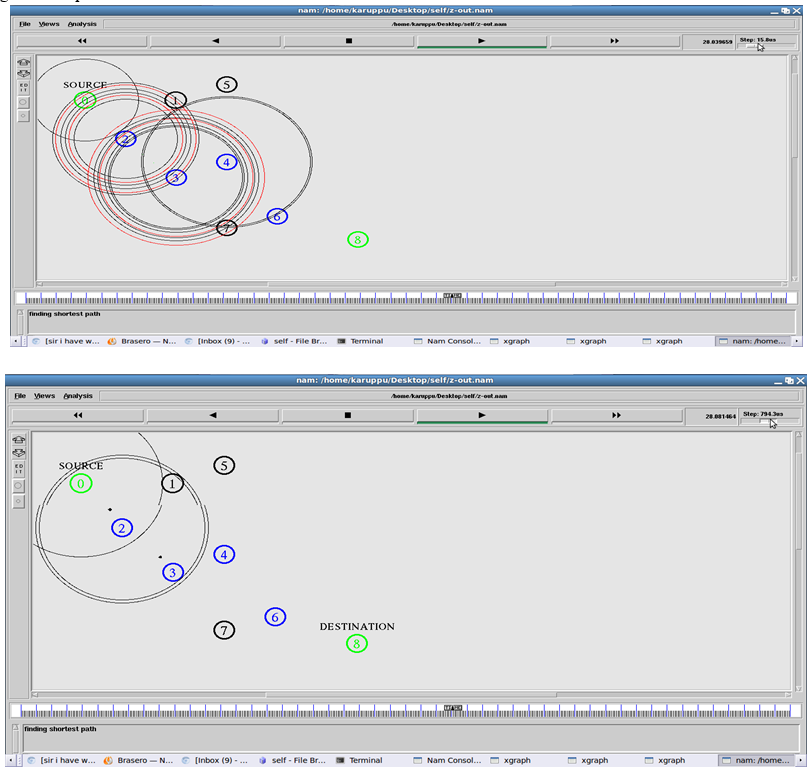
3. Failure detection and reconfiguration
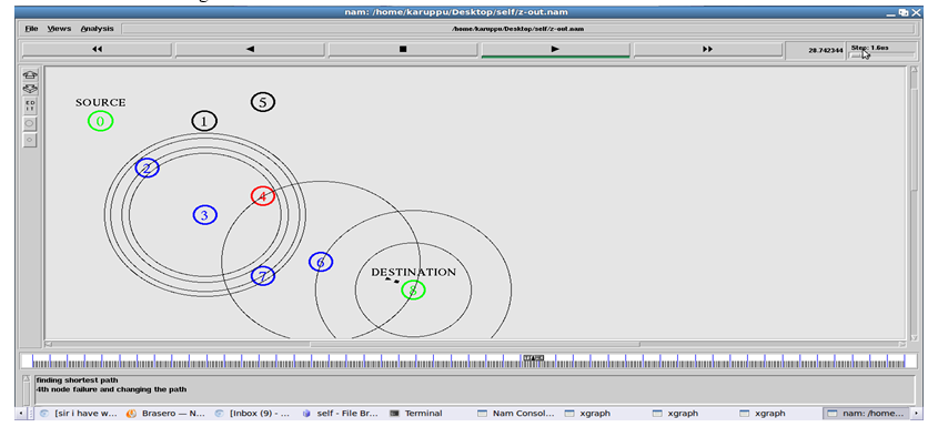
4. X GRAPH
Throughput comparison
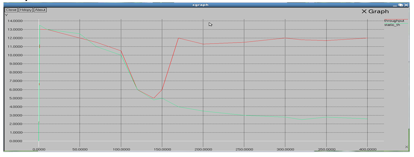
5. Packet delivery ratio
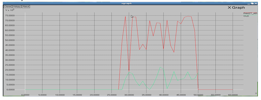
6. Efficiency
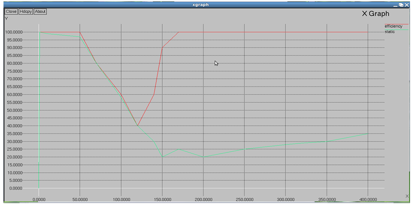
VII. FUTURE SCOPE
- Joint Optimization with Flow Assignment and Routing: ARS decouples network reconfiguration from flow assignment and routing. Reconfiguration might be able to achieve better performance if two problems are jointly considered. Even though there have been a couple of proposals to solve this problem, they only provide theoretical bounds without considering practical system issues. Even though its design goal is to recover from network failures as a best-effort service, ARS is the first step to solve this optimization problem.
- Use of ARS in IEEE 802.11 b/g WMNs: ARS is mainly evaluated in IEEE 802.11a networks, where 13 orthogonal channels are available. However, ARS can also be effective in a network with a small number of orthogonal channels (e.g., three in IEEE 802.11b/g). Because ARS includes a link-association primitive, it can learn available channel capacity by associating with idle interfaces of neighboring nodes, and it further limits the range of a reconfiguration group (e.g., nodes within 4 hops).
Conclusion
An autonomous network reconfiguration system (ARS) that enables a multi-radio WMN to autonomously recover from wireless link failures. ARS generates an effective reconfiguration plan that requires only local network configuration changes by exploiting channel, radio, and path diversity. Furthermore, ARS effectively identifies reconfiguration plans that satisfy applications’ QoS constraints, admitting up to two times more flows than static assignment, through QoS aware planning. Next, ARS’s online reconfigurability allows for real-time failure detection and network reconfiguration. Based on existing MAC, routing, and transport protocols, network performance is not scalable with either the number of nodes or the number of hops in the network. This problem can be alleviated by increasing the network capacity through using multiple channels/radios per node or developing wireless radios with higher transmission speed. However, these approaches do not truly enhance the scalability of WMNs, because resource utilization is not actually improved. Therefore, in order to achieve scalability, it is essential to develop new MAC, routing, and transport protocols for WMNs.
References
[1] Akyildiz, X. Wang, and W. Wang, “Wireless mesh networks: A survey,” Comput. Netw., vol. 47, no. 4, pp. 445–487, Mar. 2005. [2] “MIT Roofnet,” [Online]. Available: http://www.pdos.lcs.mit.edu/ roofnet [3] Motorola, Inc., “Motorola, Inc., mesh broadband,” Schaumburg, IL [Online]. Available: http://www.motorola.com/mesh [4] P. Kyasanur and N. Vaidya, “Capacity of multi-channel wireless networks:Impact of number of channels and interfaces,” in Proc. ACM MobiCom, Cologne, Germany, Aug. 2005, pp. 43–57. [5] K. Ramanchandran, E. Belding-Royer, and M. Buddhikot, “Interference- aware channel assignment in multi-radio wireless mesh networks,” in Proc. IEEE INFOCOM, Barcelona, Spain, Apr. 2006, pp. 1–12. [6] R. Draves, J. Padhye, and B. Zill, “Routing in multi-radio, multi-hop wireless mesh networks,” in Proc. ACM MobiCom, Philadelphia, PA, Sep. 2004, pp. 114–128. [7] P. Bahl, R. Chandra, and J. Dunagan, “SSCH: Slotted seeded channel hopping for capacity improvement in IEEE 802.11 ad-hoc wireless networks,” in Proc. ACM MobiCom, Philadelphia, PA, Sep. 2004, pp. 216–230. [8] D. Aguayo, J. Bicket, S. Biswas, G. Judd, and R. Morris, “Link-level measurements from an 802.11b mesh network,” in Proc. ACM SIGCOMM, Portland, OR, Aug. 2004, pp. 121–132. [9] A. Akella, G. Judd, S. Seshan, and P. Steenkiste, “Self-management in chaotic wireless deployments,” in Proc. ACM MobiCom, Cologne, Germany, Sep. 2005, pp. 185–199. [10] J. Zhao, H. Zheng, and G.-H. Yang, “Distributed coordination in dynamic spectrum allocation networks,” in Proc. IEEE DySPAN, Baltimore, MD, Nov. 2005, pp. 259–268. [11] M. J. Marcus, “Real time spectrum markets and interruptible spectrum: New concepts of spectrum use enabled by cognitive radio,” in Proc. IEEE DySPAN, Baltimore, MD, Nov. 2005, pp. 512–517. [12] M. Alicherry, R. Bhatia, and L. Li, “Joint channel assignment and routing for throughput optimization in multi-radio wireless mesh networks,” in Proc. ACM MobiCom, Cologne, Germany, Aug. 2005, pp. 58–72. [13] M. Kodialam and T. Nandagopal, “Characterizing the capacity region in multi-radio multi-channel wireless mesh networks,” in Proc. ACM MobiCom, Cologne, Germany, Aug. 2005, pp. 73–87. [14] A. Brzezinski, G. Zussman, and E. Modiano, “Enabling distributed throughput maximization in wireless mesh networks: A partitioning approach,” in Proc. ACM MobiCom, Los Angeles, CA, Sep. 2006, pp. [15] A. Raniwala and T. Chiueh, “Architecture and algorithms for an IEEE 802.11-based multi-channel wireless mesh network,” in Proc. IEEE INFOCOM, Miami, FL, Mar. 2005, vol. 3, pp. 2223–2234. [16] S. Nelakuditi, S. Lee, Y. Yu, J. Wang, Z. Zhong, G. Lu, and Z. Zhang, “Blacklist-aided forwarding in static multihop wireless networks,” in Proc. IEEE SECON, Santa Clara, CA, Sep. 2005, pp. 252–262. [17] S. Chen and K. Nahrstedt, “Distributed quality-of-service routing in ad hoc networks,” IEEE J. Sel. Areas Commun., vol. 17, no. 8, pp. 1488–1505, Aug. 1999. [18] L. Qiu, P. Bahl, A. Rao, and L. Zhou, “Troubleshooting multi-hop wireless networks,” in Proc. ACM SIGMETRICS, Jun. 2005, pp. 380–381. [19] D.Kotz, C. Newport, R. S. Gray, J. Liu, Y.Yuan, and C. Elliott, “Experimental evaluation of wireless simulation assumptions,” Dept. Comput. Sci., Dartmouth College, Hanover, NH, Tech. Rep. TR2004-507, 2004. [20] T. Henderson, D.Kotz, and I. Abyzov, “The changing usage of amature campus-wide wireless network,” in Proc. ACM MobiCom, Philadelphia, PA, Sep. 2004, pp. 187–201. [21] M. Buddhikot, P. Kolodzy, S. Miller, K. Ryan, and J. Evans, “DIMSUMnet: New directions in wireless networking using coordinated dynamic spectrum access,” in Proc. IEEE WoWMOM, Naxos, Italy, Jun. 2005, pp. 78–85. [22] R. Braden, L. Zhang, S. Berson, S. Herzog, and S. Jamin, “Resource reservation protocol (RSVP),” Internet RFC 2205 (rfc2205.txt), Sep. 1997. [23] D. S. D. Couto, D. Aguayo, J. Bicket, and R. Morris, “A high-throughput path metric for multi-hop wireless routing,” in Proc. ACM MobiCom, San Diego, CA, Sep. 2003, pp. 134–146. [24] C. Perkins, E. Belding-Royer, and S. Das, “Ad-hoc on-demand distance vector routing,” Internet RFC 3561 (rfc3561.txt), Jul. 2003. [25] D. B. Johnson and D. A. Maltz, “Dynamic source routing in ad hoc wireless networks,” in The Book of Mobile Computing. Norwell, MA: Kluwer, 1996, vol. 353. [26] G. Holland, N. Vaidya, and P. Bahl, “A rate-adaptiveMAC protocol for multi-hop wireless networks,” in Proc. ACM MobiCom, Rome, Italy, Sep. 2001, pp. 236–251. [27] J. L. Gross and J. Yellen, Graph Theory and Its Applications, 2nd ed. London, U.K.: Chapman & Hall/CRC, 2006. [28] A. P. Subramanian, H. Gupta, S. R. Das, and J. Cao, “Minimum interference channel assignment in multiradio wireless mesh networks,” IEEE Trans. Mobile Comput., vol. 7, no. 12, pp. 1459–1473, Dec. 2008. [29] A. S. Tanenbaum and M. V. Steen, Distributed Systems. UpperSaddle River, NJ: Pearson Education, 2002. [30] Q. Xue and A. Ganz, “Ad hoc QoS on-demand routing (AQOR) in mobile ad hoc networks,” J. Parallel Distrib. Comput., vol. 63, no. 2, pp. 154–165, 2003. [31] K.-H. Kim and K. G. Shin, “On accurate and asymmetry-aware measurement of link quality in wireless mesh networks,” EEE/ACMTrans. Netw., vol. 17, no. 4, pp. 1172–1185, Aug. 2009. [32] “Netfilter,” [Online]. Available: http://www.netfilter.org [33] “MADWiFi,” Linx-Consulting, Reno, NV [Online]. Available: http:// www.madwifi.org [34] “Atheros Communications,” San Jose, CA [Online]. Available: http://www.atheros.com [35] “Soekris Engineering,” Santa Cruz, CA [Online]. Available: http://www.soekris.com [36] “Iperf network measurement tool,” [Online]. Available: http://code.google.com/p/iperf [37] “The network simulator—ns-2,” [Online]. Available: http://www.isiedu/nsnam/ns [38] T. S. Rappaport,Wireless Communications: Principles and Practice. Englewood Cliffs, NJ: Prentice-Hall, 2002. [39] C. Perkins and P. Bhagwat, “Highly dynamic destination-sequenced distance-vector routing (DSDV) for mobile computers,” in Proc. ACM SIGCOMM, London, U.K., Sep. 1994, pp. 234–244. [40] M. M. Carvalho and J. J. Garcia-Luna-Aceves, “A scalable model for channel access protocols in multihop ad hoc networks,” in Proc. ACM MobiCom, Philadelphia, PA, Sep. 2004, pp. 330–344. [41] M. M. Carvalho and J. J. Garcia-Luna-Aceves, “Delay analysis of IEEE 802.11 in single-hop networks,” in Proc. IEEE ICNP, Atlanta, GA, Nov. 2003, pp. 146–155. [42] G. Bianchi, “Performance analysis of the IEEE 802.11 distributed coordination function,” IEEE J. Sel. Areas Commun., vol. 18, no. 3, pp. 535–547, Mar. 2000. [43] H.Wu, X.Wang, Y. Liu, Q. Zhang, and Z.-L. Zhang, “SoftMAC: Layer 2.5 mac for VoIP spport in multi-hop wireless networks,” in Proc. IEEE SECON, Santa Clara, CA, Sep. 2005, pp. 441–451.
Copyright
Copyright © 2022 Ranjith Pulyala. This is an open access article distributed under the Creative Commons Attribution License, which permits unrestricted use, distribution, and reproduction in any medium, provided the original work is properly cited.

Download Paper
Paper Id : IJRASET41305
Publish Date : 2022-04-08
ISSN : 2321-9653
Publisher Name : IJRASET
DOI Link : Click Here
 Submit Paper Online