

Ijraset Journal For Research in Applied Science and Engineering Technology
Mobile Crane for Workshop
Authors: Ashitosh Panhalkar, Karan Sonavane, Tejas Gaikwad, Akshay Borate, Gourav Nevase, Prof. V. V. Gundage
DOI Link: https://doi.org/10.22214/ijraset.2023.54346
Certificate: View Certificate
Abstract
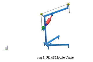
In material handling, the cranes play a vital role in modern manufacturing industries. In our project we aim to fabricate a hydraulic operated floor crane for handling various kinds of materials. The hydraulic floor crane consists of mast, boom, base, lift cylinder, hand lever, hook and wheels. The hydraulic cylinder is pumped with the help of hand lever at the same time the material with the help of hook and hydraulic cylinder released to the pressure valve so the material is unloaded. The material from one place goes to the other place with the help of hydraulic floor crane. The crane reduces the worker’s fatigue and increases the overall efficiency of production process with good safety. The crane is fabricated with complete clear front, small compact frame, good reach, high lift. The crane has the capacity of lifting 250kg to half ton with wide spread application in the shop floor. Thus the floor crane would serve as a safe and versatile model for material handling operations.
Introduction
I. INTRODUCTION
The development of lift machine or crane has reached through different time starting the first crane for lifting heavy load was invented by ancient Greeks in the late 6th century BC. The heydays of crane in ancient times come during Roman Empire when construction activity soared and buildings reached enormous dimensions. The Romans adapted the Greeks cranes and developed it further. The simplest Romans crane is the trespasses, which consists of a single beam jib, a winch, a rope, and a block containing three pulleys. Having this mechanical advantage of 3:1, it has been calculated that a single man working the winch could raise 150kg [3pulles*50kg=150kg], assuming that 50kg represent the maximum effort of a man can exert. Over a long time period heavier crane type featured five pulleys (pentaspastos) or in case of the largest one a set of three by five pulleys (polyspestos) and came with two, three, or four masts depending on the maximum loads. The polyspestos when operated by four men at both side of the winch could readily lifts 3000kg[3 ropes*5 pulleys*4 men*50kg=3000kg] If the winch was replaced by a trade wheel, the maximum load could be doubled to 6000kgs, because the trade wheel have much bigger mechanical advantages due to its higher diameters. This means comparing with the construction of Egyptian pyramid where in 50 men are needed to move 2.5 tons of stone up the ramp (50kg per persons). The lifting capability of the Roman polyspastos is proved to be 60 times higher than the Egyptian system of lifting stones. During the high middle age the trade wheel was introduced on large scale after the technology had fallen in the Western Europe with dismiss of Western Roman Empire. The earliest reference to the trade wheel reappears in the archival literature in France about 1225. Generally vertical transport could be done more safely and inexpensively by crane than customary method. Typical areas of application were harbors, mines, and in particular building sites where the trade wheel crane played a pivoted role in the construction of lofty Gothic cathedrals. In contrast to the modern cranes, middle age cranes and hoists –much like to their counter parts in Greece and Rome were primarily capable of a vertical lift, not used to move loads for considerable distance horizontally as well. It is not worthy that middle age cranes rarely featured ratchets or brakes to forestall the loads from running backwards. This curious absence is explained by a high friction force exercised by middle age trade wheels, which normally prevented the wheel from accelerating beyond control. With the onset of the industrial revolution, the first modern cranes were installed at harbors for loading cargo. It gains a dominant relevance in engineering workshops and warehouses for carrying, loading and unloading of heavy materials, mostly where there are no provisions for overhead crane. At that times even when there are overhead cranes, space might be a limiting factor to their use which makes the portability nature of the mobile floor crane a great advantage. In repair garages, it is also used in handling engines and its parts. It is also used in industries for transporting materials from one place to another. It gains relevance also in the installation of new machine, where it is used in proper positioning of the machine. Most importantly, its simplicity reduces the cost of labour as it does not require any special skill in its operation.
A. Problem Definition
Mobile cranes have specified lifting capacities based on their design and configuration. Exceeding the crane's lifting capacity can put excessive stress on the crane's structure and compromise its stability, leading to accidents and potential collapse. Overloading a mobile crane carries significant risks, including the potential for accidents, property damage, and harm to workers or bystanders. Ensuring safe load capacities is essential to protect lives, minimize the risk of equipment failure, and maintain a secure working environment.
B. Objective
- The objective of this project is to provide a hydraulic mobile floor crane equipped with a facility to lock the load at any level, in order to tackle the issue of lift cylinder failure usually experienced when using conventional designs.
- To design analytically the portable lifting machine lift slightly heavy objects that can’t be carried by single worker
- To minimize cost expenditure for fuel that is made for operating fork lift in transporting every component in the production shop
- To minimize risk of life and property
- To produce the working prototype of portable, moveable crane for the production shop
- To determine the overall cost of the crane production
- Finally, to documentation of the research project
C. Methodology
- Survey is carried out on existing lift cranes and we have decided to design and fabricate a mobile hydraulic floor crane.
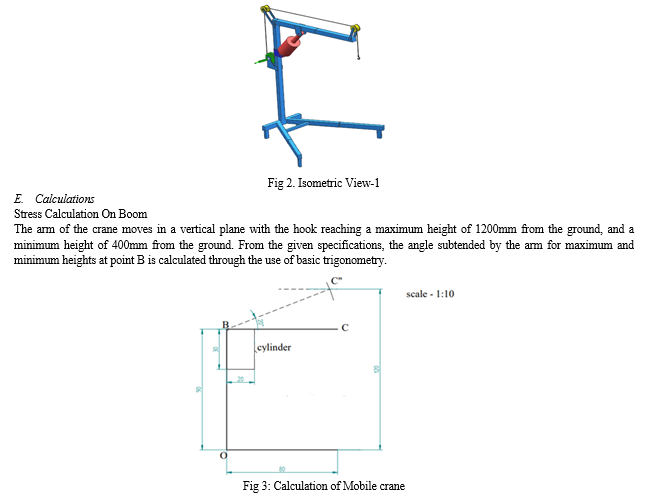
- Detail design of crane components such as mast, boom, lift cylinder and base. A 3d model of designed crane is carried out in CATIA software.
- The component of the crane are fabricated and assembled.
- Testing is carried out using the fabricated model.
II. LITERATURE REVIEW
Michael G. Kay, “Material Handling Equipment”, January 12, 2012 [1], Material handling involves short-distance movement that usually takes place within the confines of a building such as a plant or a warehouse and between a building and a transportation agency. It can be used to create “time and place utility” through the handling, storage, and control of material. The characteristics of materials affecting handling include the following: size -width, depth, height; weight; shape; and other slippery, fragile, sticky, explosive, frozen.
Some of the major equipment categories are,
- Transport Equipment. Equipment used to move material from one location to another for e.g., between workplaces, between a loading dock and a storage area, etc. The major subcategories of transport equipment are conveyors, cranes, and industrial trucks.
- Positioning Equipment. Equipment used to handle material at a single location. For e.g., to feed and/or manipulate materials so that are in the correct position for subsequent handling, machining, transport, or storage.
- Unit Load Formation Equipment. Equipment used to restrict materials so that they maintain their integrity when handled a single load during transport and for storage.
- Storage Equipment. Equipment used for holding or buffering materials over a period of time
- Identification and Control Equipment. Equipment used to collect and communicate the information that is used to coordinate the flow of materials within a facility and between a facility and its suppliers and customers.
Ibrahim O Abdulmalik, “Design and manufacture of a hydraulic workshop crane”, ISSN 2319-5991, Vol. 3, No. 3, August 2014 [2], Oil at high pressure from the reservoir is sent to one end of the cylinder through the rubber pipes. The oil exerts pressure on the piston and thus pushes it upwards. Process goes on and the entire side of the cylinder is filled with oil and thus moving the piston to its extreme. The release liver valve is used to bring the piston back to its original position. The hydraulic oil returns back to reservoir.
K Suresh Bollimpelli1, “Design and Analysis of Column Mounted JIB Crane”, 2015 [3], In this work, a static, modal and harmonic analysis of a column mounted jib crane using ANSYS software is presented. A column mounted jib crane of 1.5 Ton capacity is modelled using CATIA which is imported into ANSYS where calculations are performed. The detailed drawing of various parts of the crane is obtained from TATA Advanced systems Ltd (TASL) Adibhatta village, Hyderabad. The deflection values, Von Misses stress etc are obtained using the static analysis. The hand calculations of the column mounted jib crane have been done using simple strength of material expressions. The deflection is obtained as 3.709mm, when the load applied is 1.5 tons. The maximum stress obtained is 147.8Mpa which is less than the allowable stress. The static stress was found to be within the limits of safety. The model analysis shows the natural frequencies of the crane to be in the lower range 0-10Hz.
The fundamental frequency is found out to be 0.323589 Hz. All the other higher frequencies are also found to be very low making the jib crane less stiff and highly stable for any transient loading. The harmonic analysis is performed with a view to predict the performance of the crane if a cycle time dependent load is allowed to act at the trolley. For this hypothetical situation, the von-mises stress and displacement along the z-directions were obtained using ANSYS. The maximum von-Mises stress of 60Mpa occurs at fundamental frequency of 1 Hz. The maximum z-direction displacement of 5mm was observed. These values indicate that the column mounted jib crane is safe to operate under the load of 1.5 Tons under static and cyclic time dependent loads also.
Okolie Paul Chukwulozie, “Steel Work Design and Analysis of a Mobile Floor Crane” 2016 [4], the transportation of heavy machine parts and equipment within and outside the workshop has been a source of concern and needs urgent attention because of the hazard it exhibits. This negative effect on the health of engineers, led to the invention of the floor jib crane but research shows that contemporary designs of floor jib crane fail over time when these static load is left on it for a prolonged period of time. This project is centred on the design and fabrication of a mobile floor crane equipped with a facility to lock the load at any level as a special feature, to tackle the issue of failure due to static load. The mobile crane is designed to bear a maximum load of about 1000 kg, with a counter weight of 2.6 KN which gave the crane a 3.034 factor of safety. The materials employed are; sheet metals, angular iron, bolts, nuts, metal rollers etc. The fabrication processes involved drawing, marking out, cutting, filling, welding and assembling. For permanent joints, the arc welding process was employed. As indicated earlier, the mobile floor crane gains its significance in the transportation of heavy machine parts within and outside the workshop. It can also be used to load and unload machine parts on trucks.
III. DESIGN AND CALCULATIONS
The designing work was carried out using CATIA software. The required dimensions of the driver and the driven wheels were taken as per the design equations. CATIA is the most widely used design software's which helps in designing 2 as well as 3 dimensional models using simplified alphabetical and numerical commands. Both the driving and the driven wheels were drawn to the required dimensions using the circle command.
A. Design Criteria
There are three major considerations in the design of cranes.
· The crane must be able to lift the weight of the load.
· The crane must not topple.
· The crane must not rupture.
B. Lifting Capacity
The lifting capacity of hydraulic crane mainly depends on following. The Lever: A balance crane contains a horizontal beam pivoted about a point called the fulcrum. The principle of the lever allows a heavy load attached to the shorter end of the beam to be lifted by a smaller force applied in the opposite direction to the longer end of the beam. The ratio of the load's weight to the applied force is equal to the ratio of the lengths of the longer arm and the shorter arm, and is called the mechanical advantage. The lifting capacity of this crane is about 150Kg considering factor of safety.
C. The Hydraulic Cylinder
This can be used directly to lift the load or indirectly to move the jib or beam that carries another lifting device. Cranes, like all machines, obey the principle of conservation of energy. This means that the energy delivered to the load cannot exceed the energy put into the machine. For example, if a pulley system multiplies the applied force by ten, then the load moves only one tenth as far as the applied force. Since energy is proportional to force multiplied by distance, the output energy is kept roughly equal to the input energy (in practice slightly less, because some energy is lost to friction and other inefficiencies). The same principle can operate in reverse. In case of some problem, the combination of heavy load and great height can accelerate small objects to tremendous speed. Such projectiles can result in severe damage to nearby structures and people. Cranes can also get in chain reactions; the rupture of one crane may in turn take out nearby cranes. Cranes need to be watched carefully.
D. Stability
For stability, the sum of all moments about any point such as the base of the crane must equate to zero. In practice, the magnitude of load that is permitted to be lifted (called the "rated load" in the US) is some value less than the load that will cause the crane to tip (providing a safety margin).
Standards for cranes mounted on ships or offshore platforms are somewhat stricter because of the dynamic load on the crane due to vessel motion. Additionally, the stability of the vessel or platform must be considered. For stationary pedestal or kingpost mounted cranes, the moment created by the boom and load is resisted by the pedestal base or kingpost. Stress within the base must be less than the yield stress of the material or the crane will fail.
V. ADVANTAGES, DISADVANTAGES AND APPLICATIONS
A. Advantages:
- Most powerful means of lifting objects: It is one of the most powerful means of lifting objects is with the strength of a hydraulic crane. By harnessing the strength that liquid under pressure gives, and the ease with which it can be used, it is possible to transfer a relatively small amount of effort from one place to another, and hydraulic cranes are amongst the most efficient lifting systems available in the modern workplace.
- Extremely stable in use: Because the hydraulic cranes use a fixed system of pipes, constant pressure can be maintained once a part of the system has been moved into place, and this makes them extremely stable in use, and able to support relatively large weights.
- Very easy to maintain: Hydraulic cranes are amongst the simplest systems that you can use within any industrial process, and are very easy to maintain. Provided that all the pumps and pistons are regularly checked for any leaks, and potential stress points where the levers are supported are inspected for damage, the crane will continue to operate completely reliably for long periods of time
- A very versatile tool: Most hydraulic cranes are comparatively light weight, and the ease with which they can be moved from one area to another within the factory or distribution centre, makes them a very versatile tool with lots of uses on a day to day basis. From simple loading jobs in your loading bay area where the portable hydraulic cranes can be used to lift objects into a waiting truck to more complex jobs within the main factory, the lifts will come in very useful.
- Quite simple Design: A hydraulic system works with a system of pumps and pistons that are filled with a liquid, usually a light oil or water. By moving the liquid under pressure from the pumps, pistons can be extended or reduced, and when these pistons are connected to a system of levers, the pistons can be used to lift surprisingly heavy weights.
B. Application of Cranes
- Cranes exist in an enormous variety of forms – each tailored to a specific use. Sometimes sizes range from the smallest jib cranes, used inside workshops, to the tallest tower cranes, used for constructing high buildings. For a while, mini - cranes are also used for constructing high buildings, in order to facilitate constructions by reaching tight spaces. Finally, we can find larger floating cranes, generally used to build oil rigs and salvage sunken ships.
- These days hydraulics principle is being used extensively in material handling processes through cranes. Depending on the loads to be handled and the operations to be performed there are different types of cranes like Crawler Cranes, Truck Cranes, and Floor Cranes.
- Hydraulic Crawler cranes are used for picking and moving huge amount of loads. Generally loads are kept in containers for Bulk loading.
- Hydraulic truck cranes have good flexibility with high load carrying capacities. Ø Hydraulic workshop foldable crane used in industries for moving small to medium sized materials from one place to other. The load carrying capacity can vary from 80 kg to half ton.
VI. ACKNOWLEDGMENT
It is our great pleasure to thank everyone who has helped in making this work possible. First I want to express sincere gratitude to our project guide Prof. Gundage V.V. for his helpful guidance, inspiration, and support during the entire project work. We thank to our H.O.D. Prof. G.V. Thombare and project Coordinator Prof. A. M. Kazi for their assistance during the project period and the preparation for this project. We are grateful to our Principal for showing interest in all the activities related to the project. I also like to thank my family for supporting me through this project activity. Last but not the least, we acknowledge all those who helped us directly or indirectly during this project and making of this report.
Conclusion
The aim of our project was to build a fully functional Hydraulic Mobile Crane mechanism which is capable of lifting load up to 150 kg from the hook attached to the horizontal arm. We accurately achieved our first goal of lifting the load from the hook by up and down movement of the horizontal arm. We feel that our design and fabrication was a great success both in terms of strength and stiffness. Our project weighed 20 kg which is capable of lifting load up to 150 kg using hydraulic power.
References
[1] Michael G. Kay, “Material Handling Equipment”, January 12, 2012 [2] Ibrahim O Abdulmalik, “Design and manufacture of a hydraulic workshop crane”, ISSN 2319-5991, Vol. 3, No. 3, August 2014 [3] K Suresh Bollimpelli1, “Design and Analysis of Column Mounted JIB Crane”, 2015 [4] Okolie Paul Chukwulozie, “Steel Work Design and Analysis of a Mobile Floor Crane” 2016 [5] International Journal of Engineering and Advanced Technology (IJEAT) ISSN: 2249 – 8958, Volume-3, Issue-2, December 2013. [6] Machine Design by Khurmi Gupta. 3. [7] http://www.c1call.co.uk/c1/Assets/Products/MaterialHandling_FloorCrane_Heavy Duty.jpg. [8] British Journal of Applied Science & Technology .13(5): 1-9, 2016, Article no.BJAST.23079. [9] International Journal of Biotech Trends and Technology (IJBTT) – Volume2 Issue 1 Number1–Jan 2012.
Copyright
Copyright © 2023 Ashitosh Panhalkar, Karan Sonavane, Tejas Gaikwad, Akshay Borate, Gourav Nevase, Prof. V. V. Gundage. This is an open access article distributed under the Creative Commons Attribution License, which permits unrestricted use, distribution, and reproduction in any medium, provided the original work is properly cited.

Download Paper
Paper Id : IJRASET54346
Publish Date : 2023-06-22
ISSN : 2321-9653
Publisher Name : IJRASET
DOI Link : Click Here
 Submit Paper Online