

Ijraset Journal For Research in Applied Science and Engineering Technology
Numerical and Analytical Investigation of Forming Limit Diagram of SS316L foil
Authors: Omkar Godage, Ganesh M Kakandikar
DOI Link: https://doi.org/10.22214/ijraset.2022.40899
Certificate: View Certificate
Abstract
In process of sheet metal forming, forming limit is characterised by the start of cracking, wrinkling, necking and it is crucial to know the limit up to which the sheet metal can be formed. Forming limit diagram (FLD) gives a brief idea about major and minor strains along with forming limit curves. The mainly three ways for plotting of FLD as given analytical, numerical, and experimental. The research work presents micro-forming investigations on an stainless steel sheet of 50 microns, to plot FLD, using the limit dome height test in accordance with to ASTM E2218-02 standard. Forming limit diagram (FLD) offers a suitable and useful tool to predict the forming behaviour of the sheet metals. This paper is concentrated on the plotting of FLD for stainless steel(SS-316L). Numerical and analytical approach are used to develop forming limit diagram of ultra thin SS316L metal foil.
Introduction
I. INTRODUCTION
The process in which sheet metals are modified to a required shape instead of removal of any materials from it is called sheet metal forming. In this process a force is generated that stresses the material to deform plastically. This in turn gives the chances to deform bend or stretch the sheet to a variety of shapes. This forces the metal past its yield strength, that causes the material to plastically deform until it fails. By doing so, the sheet can be bent or stretched into a variety of complex shapes. Sheet metal forming processes include the following:deep drawing, stretching, bending, roll forming, stretch forming etc. Formability of the sheet metals is evaluated by the major and minor strain during deformation and is predicted in terms of forming limit diagram (FLD), which shows various deformation paths of the material. Vinod Laxman Hattalli et al. [1] surveyed for innovation in sheet metal forming. This paper focuses light on the ongoing examination and advancements in the sheet metal forming in recent two decades. Forming limit diagram is characterizing failure criteria in sheet metal forming procedures. Forming limit diagram is key component in sheet metal forming. Minimization of products in various areas of engineering is a current trend in global, that allows product functionality which is to be achieved in micro-components with the aim of reduction of weight, volume, expenses. Micro-parts are the parts which are very tiny, mainly dimensions less than of millimeters. These parts must be accurately manufactured so as to satisfy the precision range of few microns[2].J Sahu et al. [3] , conducted limiting dome test for thin brass sheet metal foil and plotted FLC using uniaxial, plane, and biaxial strain specimen.V R. Shinge et al. [4] utilized experimental strategy for discovering forming limit diagram. Experimental technique is utilized to create FLD of Mild Carbon steel sheet metal.Limit Dome Height testing is applied by the American Society of Testing Material (ASTM) as described in ASTM E 2218-02.Anil Mashalkar et al.[5] conducted research work that presented experimental and analytical investigations to derive FLC of thickness 0.09-mm thin brass metal foil. Microforming experiment setup was developed and tests were conducted in accordance to ASTM standards by using 15 mm hemispherical punch for six various size specimens.Marrapu Bhargava et al. plotted forming limit diagram based on strain path graph[6].Paper explains materials utilized for examination of TRIP (Transformation Induced Plasticity) steel and Q&P (Quenched and Partitioned) steel.The FLC dependent on new strain localization criterion basis shows better concurrence with experimental FLC contrasted with other failure criterion. Correspondingly this analyst additionally researched on AA 5182 Aluminum for forming limit diagram utilizing strain path. For various evaluation of aluminum "Al 3105 sheet" M.M. Moshksar et al.[7] characterized a forming limit curve.In this paper all samples were set up in rolling direction and annealed before testing. Xu et al.[8] linked effect of size with forming behavior of materials during plastic zone using experimental and other modeling techniques.R Zhang et al. [9] evaluated modeling approaches to find formability of the material. Michael Abspoel, Marc E. Scholting and John M.M. Droog[10] find out new empirical calculation for plotting forming limit curve. According to their method only tensile test is sufficient to predict forming limit curve. In this method they plotted four point forming limit curves. It is possible that we can validate FLD utilizing FEA investigations as with experimental done by [11]K.Sajun Prasad, T. Kamal, S.K. Panda,S. Kar,S.V.S.
Narayana Murty and S.C Sharma. Q. Situ, M.K. Jain, D.R .Metzger[12] proposed a new methodology to obtain FLD from experimental approach and finite eliminate simulation of experiment. S. Ahmadi et al.[13] explained experimental and analytical methods for forming limit diagram. In this paper, forming limit diagrams (FLDs) for LC (Low Carbon) and ULC (Ultra Low Carbon) steels and the impact of various parameters like the work-hardening exponent(n) and the plastic strain ratio(r) on these graphs have been assessed and investigated utilizing ABAQUS.W Bleck, Z Deng [14] did near investigations of on possible forming limit diagram for steel sheet.Hendra Hermawan [15] studied about various biomaterial and metal implants in human body.Currently many research and examination is in process for forming limit diagrams for various materials.
In this paper analytical FLD for ultra thin SS-316L foil has been developed using M. Abspoel approach. According to their method tensile testing is enough to predict forming limit curve. Numerical FLD is plotted by simulating limiting dome height punch tests on various width specimens by using ABAQUS software. Analytical FLD is compared with numerical FLD.
II. MATERIAL AND METHOD
A. Material characteristics
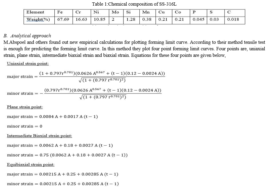
SS-316L is a type of austenitic chromium-nickel stainless steel with higher resistance to corrosion. In comparison with other chromium-nickel austenitic stainless steels, SS-316L contains an excess of molybdenum content which provides it a improved corrosion resistance. 316L grade of stainless steel is until now a majorly used alloy in majority implants sector from cardiovascular, dental, orthopaedic to otorhinology. In orthopaedical sector, appropriate for bone fixing such as plate, screw; and artificial joints because of its potential to substitute the function of hard tissues. It includes electronics, pharmecutical,automotive, and medical implants, that includes pins, screws and orthopedic implants like hip and knee replacements. This research work presents numerical and analytical investigations to develop FLC of 0.05-mm (50 μm) ultra-thin SS316L foil.
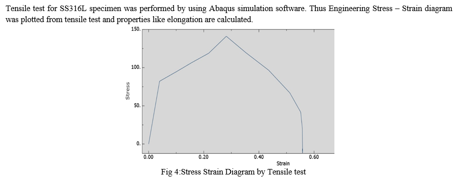
C. Tensile Test Simulation
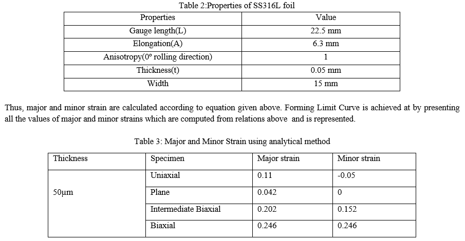
As researchers define, according to their method required properties for plotting forming limit diagram are elongation(A), anisotropy(r) and material thickness(t). Tensile test must be carried out to get value of these properties. Specimen for tensile test is as shown in figure 1.

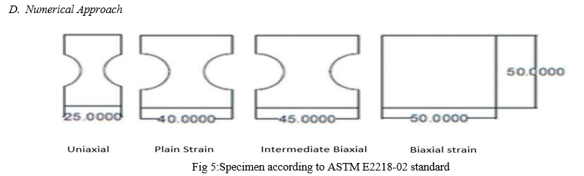
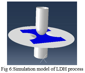
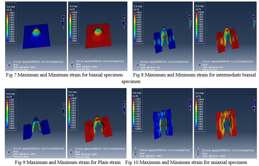
Uniaxial, Plain-strain, Intermediate-Biaxial, Biaxial strain specimens are used according to ASTM E2218-02 standard. CAD models of Punch, Die, Holder were designed and numerical investigation was performed by using Abaqus Explicit software. Thus, simulation for above mentioned specimen was performed and values for maximum and minimum strain were calculated. Velocity of punch was 0.05mm/s and time period was 10 sec.
III. RESULTS AND DISCUSSION
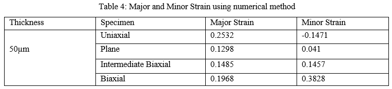
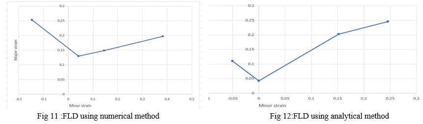
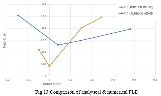
In this research forming limit diagrams for ultra thin SS316L metal foil are developed using numerical and analytical method. Specimens like Uniaxial,Biaxial,Intermediate Biaxial and Plane strain were considered and points are plotted on FLD.Numerical FLD is plotted in Fig.11 and Analytical FLD is plotted in Fig.12.Lastly in Fig.13 numerical and analytical FLD have been compared.
 ???????
Conclusion
A. The FLCs have been obtained for thin SS316L foil which would be advantageous for more researchers to design components for micro-forming. B. Material failure(i.e.necking) can be observed in numerical approach at points of maximum and minimum strain which indicates its forming limit. C. Uniaxial strain points have more variation than biaxial and plain strain points. D. This research sets a fundamental benchmark by plotting FLD which will assist scholars further for design and manufacturing of parts via microforming specially for biomedical applications as well as other applications of SS316L. E. The analytical method presented gives a greater understanding in the formability of material with minimum efforts and with no experimentation.
References
[1] Vinod Laxman Hattalli, Shivashankar R. Srivatsa, “Sheet Metal Forming Processes – Recent Technological Advances”. Journal of Materials Today: Proceedings 5 (2018) 2564-2574. [2] Akhtar Razul Razali, Yi Qin, “A Review on Micro-manufacturing, Micro-forming and their Key Issues”. Journal of Procedia Engineering 53 (2013) 665-672. [3] Jambeswar Sahu, Sushil Mishra, “Limit dome height test of very thin brass sheet considering the scaling effect”. Journal of Physics: Conference Series 734 (2016) 032114. [4] Vishwajeet R. Shinge, Uday A. Dabade, “Experimental Investigation on Forming Limit Diagram of Mild Carbon Steel Sheet”. Journal of Procedia Manufacturing 20 (2018) 141-146. [5] Anil Mashalkar, Ganesh Kakandikar, Vilas Nandedkar, “Microforming analysis of ultra-thin brass foil,” Materials and Manufacturing Processes (2019) DOI: 10.1080/10426914.2019.1655158 [6] M. Bhargava, A. Tewari, and S. Mishra, “Strain path diagram simulation of AA 5182 Aluminum alloy,” Procedia Eng., vol. 64, pp. 1252–1258, 2013. [7] M. M. Moshksar and S. Mansorzadeh, “Determination of the forming limit diagram for Al 3105 sheet,” J. Mater. Process. Technol., vol. 141, no. 1, pp. 138–142, 2003. [8] L. F. Peng, Z. T. Xu, M. W. Fu, and X. M. Lai, “Forming limit of sheet metals in meso-scale plastic forming by using different failure criteria,” Int. J. Mech. Sci., vol. 120, no. November 2016, pp. 190–203, 2017. [9] R. Zhang, Z. Shao, and J. Lin, “A review on modelling techniques for formability prediction of sheet metal forming,” Int. J. Light. Mater. Manuf., vol. 1, no. 3, pp. 115–125, 2018. [10] M. Abspoel, M. E. Scholting, and J. M. M. Droog, “A new method for predicting Forming Limit Curves from mechanical properties,” J. Mater. Process. Technol., vol. 213, no. 5, pp. 759–769, 2013. [11] K. S. Prasad, T. Kamal, S. K. Panda, S. Kar, S. V. S. Narayana Murty, and S. C. Sharma, “Finite Element Validation of Forming Limit Diagram of IN-718 Sheet Metal,” Mater. Today Proc., vol. 2, no. 4–5, pp. 2037–2045, 2015. [12] Q. Situ, M.K. Jain, D.R .Metzger, “Determination of Forming Limit Diagram of sheet materials with a hybrid experimental-numerical approach,” Int. J. Mech. Sci., vol. 53, no. November 2011, pp. 707–719, 2011 [13] S. Ahmadi, A. R. Eivani, and A. Akbarzadeh, “Experimental and analytical studies on the prediction of forming limit diagrams,” Comput. Mater. Sci., vol. 44, no. 4, pp. 1252–1257, 2009. [14] W. Bleck, Z. Deng, K. Papamantellos, and C. O. Gusek, “A comparative study of the forming-limit diagram models for sheet steels,” J. Mater. Process. Technol., vol. 83, no. 1–3, pp. 223–230, 1998. [15] Hendra Hermawan, Dadan Ramdan and Joy R. P. Djuansjah “Metals for Biomedical Applications,” Biomedical Engineering – From Theory to Applications 17(2011) 411-430
Copyright
Copyright © 2022 Omkar Godage, Ganesh M Kakandikar. This is an open access article distributed under the Creative Commons Attribution License, which permits unrestricted use, distribution, and reproduction in any medium, provided the original work is properly cited.

Download Paper
Paper Id : IJRASET40899
Publish Date : 2022-03-21
ISSN : 2321-9653
Publisher Name : IJRASET
DOI Link : Click Here
 Submit Paper Online