

Ijraset Journal For Research in Applied Science and Engineering Technology
Numerical Study of Exhaust Manifold
Authors: Bangaru Bharath Kumar
DOI Link: https://doi.org/10.22214/ijraset.2022.41394
Certificate: View Certificate
Abstract
The Exhaust manifold is an important component which affects the performance of the I.C engine. The exhaust system for any type of vehicle consists of an exhaust manifold, catalytic converter, resonator and a muffler which is connected to a tailpipe. Exhaust gases at the end of exhaust stroke are sent to the exhaust manifold through exhaust valves. The exhaust manifold has to withstand and operate under high exhaust temperature and pressure. The design aspect of the exhaust manifold has to be done through trial and error method to find the optimum layout to extract the performance of the manifold. In this paper, we will analyse the exhaust manifold through conjugate heat transfer.
Introduction
I. INTRODUCTION
In a 4-stroke IC engine, the exhaust manifold is critical. An engine's exhaust manifold is attached to the cylinder head. Exhaust gases from several cylinders are collected in one pipe by the exhaust manifold. When the exhaust valve opens and the inlet valve remains closed throughout the exhaust stroke, the piston moves from bottom dead centre to top dead centre,
Sweeping away the burned gases from the cylinders. These exhaust gases exit the cylinder and pass through the catalytic converter. The temperature of these hot gases is around 800 ?, with pressures ranging from 100 to 500 kpa..During the exhaust stroke, this temperature and pressure are experienced. Grey cast iron is a form of cast iron with a graphitic microstructure that can withstand rapid and severe temperature fluctuations, making it ideal for exhaust manifolds. The exhaust manifold can get practically red hot while the engine is working hard. As a result, we must conduct an experimental investigation on the exhaust manifold's whole behaviour. For an engine exhaust system, merely flow or thermal analysis is insufficient; we must also understand the thermal behaviour of the structure as a function of fluid parameter and vice versa via conjugate heat transfer.Conjugate Heat Transfer (CHT) is a term used to describe processes that involve simultaneous energy exchange between the solid and fluid domains as a result of interaction. It is commonly used in engineering applications such as internal combustion engines, turbomachinery, heat exchangers, and so on.
II. LITERATURE REVIEW
The Numerical Simulation is carried out on the ANSYS FLUENT software. When compared between steady and transient state analysis of Exhaust Manifold, Transient State analysis is found to be more accurate, practical and realistic way in the design procedure. Conjugate Heat Transfer analysis of Exhaust Manifold is done on ANSYS FLUENT.
The effects of temperature on exhaust manifold modal analysis was investigated by Bin Zou, et al.[1]. The temperature field is mapped from the CFD study, and the heat conduction process is then analysed in FEM software with the temperature field boundary conditions. Finally, a modal analysis that takes into account the temperature impact is performed. When comparing the frequency and vibration mode of cold and warm modals, it is discovered that temperature has a significant impact on the manifold mode, which is extremely useful for product design.
Sweta Jain, et al.[2] investigated the associated thermal stresses and deformations under simulated operational conditions close to the real situation on different materials at different ambient temperatures, such as cast iron and structural steel, in their paper "The Sequential Coupled Thermal Structural Analysis." Under the thermal field and structural analysis, the linear steady state temperature distribution is computed. The goal of this study is to guarantee that the material used is appropriate for the specified design in terms of exhaust manifold serviceability.
J.David Rathnaraj [3] studied the thermomechanical fatigue of stainless steel exhaust manifolds in his work. Temperature gradients and geometrical restrictions cause significant thermal stress in automotive engines. One of the most difficult difficulties in automobile engineering is the thermomechanical coupling. Thermal fatigue analysis is taken into account throughout the exhaust manifold design process. The application of the constitutive equation to the thermomechanical state of a model based on isothermal data is the topic of this research. The thermal stress analysis and life prediction of an exhaust manifold manufactured of 429 EM stainless steel are performed using the suggested model.
In their study "Optimal design of vehicle exhaust system using gt- power," A.K.M. Mohiuddin et al.[4] built an exhaust system using GT-Power software and compared its performance to that of an existing system. The newly constructed exhaust manifold has a decreased back pressure, resulting in improved engine performance.
Swathi Satish, et al.[5] compares predictions obtained using conformal and indirect interfaces for Conjugate Heat Transfer (CHT) analysis in an exhaust manifold to determine the degree of proximity of certain pre-defined physical variables.The RANS k-epsilon turbulence model was used to perform a steady-state study for base mesh size values of 2 mm and 4 mm. At the two base mesh size values, the predicted outcomes for the conformal and non-conformal meshes were found to be in good agreement.
III. METHODOLOGY
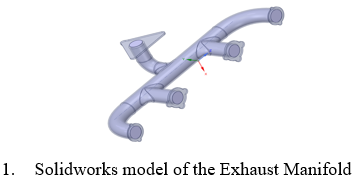
A. Geometric Modelling
The exhaust manifold design is created in solidworks software and imported into spaceclaim as a STEP file. In spaceclaim, the model is checked for interferences, extra lines or volumes which may obstruct smooth simulation. Afterwards, the volume of the exhaust manifold is extracted. The volume through which the hot exhaust gases exit from the exhaust valve. The extraction of fluid volume in an exhaust manifold is an important step in the simulation as it allows the solver to distinguish between the solid volume and liquid volume. An important part of this simulation is the ‘Share Topology’ option in spaceclaim. This option allows for the communication and transfer of heat and data during the simulation, which is an integral part for Conjugate Transfer Analysis.
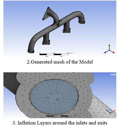
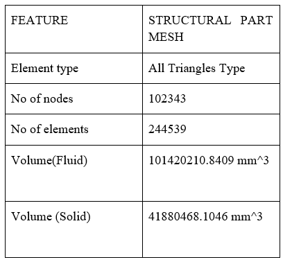
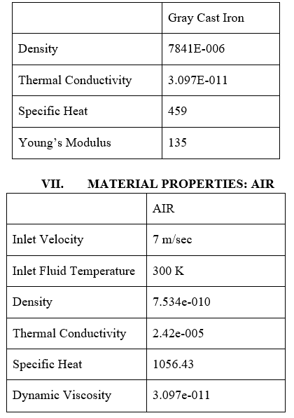
IV. MESH GENERATION
The backbone of the finite element approach is mesh creation. The production of nodal coordinates and elements is referred to as mesh generation. It also offers automated node and element numbering depending on a little bit of data given by the user. Automatic mesh production lowers mistakes and saves a significant amount of time for the user, lowering FEA costs. In Solidworks software, the model exhaust manifold is created. In ANSYS, the meshing of the model is done. Exhaust Manifold is divided into two parts, Solid volume and Fluid volume, which aids in the setup part of the simulation. The Basic meshing is done in ANSYS meshing.
V. ANALYSIS
To calculate the pressure drop, a steady state single phase single species simulation using exhaust gas as the working fluid will be run for the geometry at a specific inlet velocity. Solidworks will be used to build the geometry, and a multiblock structured mesh will be created in ANSYS meshing. The flow simulation under isothermal conditions will be performed using ANSYS Fluent. ANSYS Workbench will be used to conduct the entire analysis. For exhaust gas, a steady state single species simulation will be run under isothermal circumstances. The k- epsilon RNG turbulence model, which accounts for high velocities and severe streamline curvature in the flow domain, will be used to represent turbulence.
VI. EXHAUST MANIFOLD: MATERIAL PROPERTIES: GREY CAST IRON
The Geometry is divided into two different sections to allow the smooth transfer of data and Heat transfer for better Simulation.
The sections are divided into 2 parts
- Fluid Section
- Solid Section
VIII. BOUNDARY CONDITIONS
References were used to derive all of the values for the fluid flow boundary condition. When the input speed is 1 m/s and the temperature is 523K, the exhaust gases mix in a vorticity-like manner, and static pressure is insignificant. The viscous fluids state that near a solid barrier, the fluid will have zero velocity relative to the boundary, which is known as the no slip wall condition. Turbulence modelling is a critical topic in most CFD simulations. Spalart-Allmaras is a one-equation model that solves a viscosity-like variable transport equation. The spalart allmaras variable is a name for this. For a structural component, the interface wall mapping comes from a simulation calculation. References were used to derive all of the values for the thermal boundary condition. The heat transfer coefficient (K) is the temperature differential between the solid surface and the surrounding fluid region. It is used to calculate heat transfer between a fluid and a solid, often through convection or phase change.
IX. SOLVER CONDITIONS
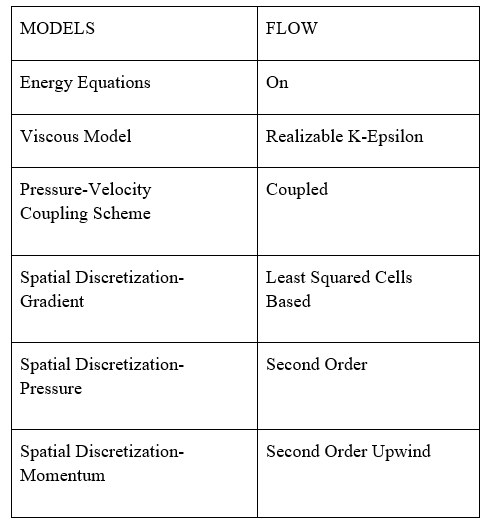
X. RESULTS AND DISCUSSIONS
The models are analysed using CFD and the results obtained are shown in the colour Contours
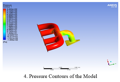
A. Pressure Contours for Exhaust Manifold
The high pressure at the head is caused by a large pressure differential between the exhaust in the combustion chamber and the surrounding environment. The pressure in the current manifold is equally distributed, as shown in Fig., and the effect of uniformly distributed pressure has an impact on the velocity of the exhaust gas flow. Because the pressure flow via the exhaust manifold's output should be evenly distributed, the present manifold design is developed and tested.
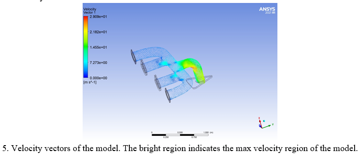
B. Velocity Contours For Exhaust Manifold
The initial velocity is given as 7 m/sec at all inlets. Due to the convergence of the exhaust valves into a single exhaust pipe. The velocity of the exhaust gas multiplies. The max velocity region of the component is observed to be near the exhaust pipes shown by the red region in the velocity contour.
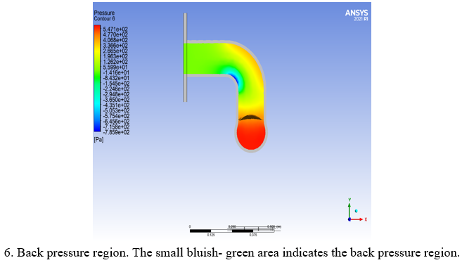
C. Back Pressure Zone
Back pressure is the pressure put on a flowing fluid by impediments that are obstructing its flow direction. Back pressure created by an automotive engine's exhaust system has a detrimental impact on the engine's performance since it restricts the flow rate of exhaust gases, resulting in lower engine power.
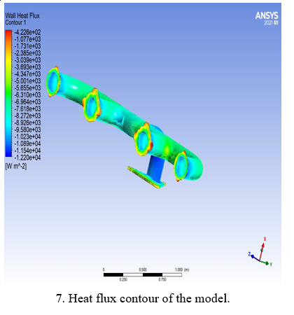
D. Surface Heat Flux
In the Heat Flux Contour, the surface heat flux distribution inside the exhaust manifold can be seen. The rate of heat energy movement through a specific surface, per unit surface, is known as heat flux or thermal flux.
E. Surface Heat Transfer Coefficient
The Surface Heat Transfer Coefficient (K) is the temperature differential between the solid surface and the surrounding fluid region. It is used to calculate heat transfer between a fluid and a solid, often through convection or phase change.
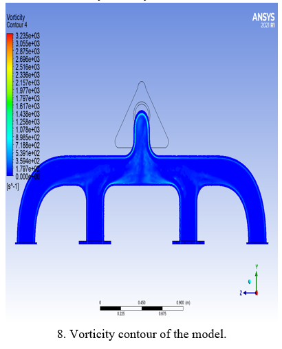
F. Vorticity
The localised rotation of a fluid component is measured by vorticity. The rotation of the exhaust fluids inside the manifold is known.
Conclusion
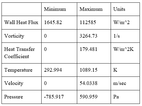
The CHT analysis of the exhaust is conducted to see the performance of the exhaust manifold in its working conditions. Contours are created and attached. Initial Velocity, which is given as 7 m/sec. The fluid attains the max velocity at the exhaust pipe reaching upto 54.0338 m/sec. The Exit Temperature of exhaust is noted as 1089.15K. Max Heat Transfer Coefficient attained is 179.481 W/m^2K. Wall Heat Flux is recorded as 112585W/m^2. The Tabulated results are attached below.
References
[1] Vivekanand Navadagi, Sidda veersanganad “Cfd analysis of exhaust manifold of multi cylinder petrol engine for optimal geometry to reduce back pressure” International journal of engineering Research and Technology (IJERT) March-2014 [2] Bin zhou Yuqian Hu, Zhien Liu Fuwu Yan and chaowang.”The impact of Temperature effect on exhaust manifold Thermal modal analysis” Research journal of applied science Engineering and Technology Aug 20, 2013 [3] SwathiSatishmani ,prithviraj and shridharani “comparison of prediction obtained on an exhaust manifold analysis using conformal and indirect mapped interface” . International congress on computational mechanics and simulation(ICCMS),IIT hyderabad 10-12 Dec 2012 [4] Xueyuan ZHANG YuLUO And Jianhua Wang “Coupled Thermal Fluid-solid Analysis of engine Exhaust manifold considering welding Residual stresses” Transaction of JWRI special issue on WSE2011(2011) [5] Gopaal , MMM Kumara varma , “Exhaust manifold design –FEA Approach”(IJETT) Volume 17 number 10 – november [6] Zhi-EN Liu, Xue-Nili “Numerical simulation For exhaust manifold based on the serial coupling of STAR-CCM+ AND ABAQUS Research” journal of Applied sciences ,Engineering & Technology , Nov 10 ,2013 [7] Gopal, MMM Kumara verma “Thermal and structural Analysis of An Exhaust manifold of A multi cylinder engine” (IJMET) vol 5 12 DEC(2014)
Copyright
Copyright © 2022 Bangaru Bharath Kumar. This is an open access article distributed under the Creative Commons Attribution License, which permits unrestricted use, distribution, and reproduction in any medium, provided the original work is properly cited.

Download Paper
Paper Id : IJRASET41394
Publish Date : 2022-04-12
ISSN : 2321-9653
Publisher Name : IJRASET
DOI Link : Click Here
 Submit Paper Online