

Ijraset Journal For Research in Applied Science and Engineering Technology
Omni wheels Robot for Effective Surveillance and Transportation Purpose
Authors: Prof. A. V. Wanjari , Priti S. Mondhe, Naba Raza , Nikhil S. Meshram , Nikita U. Khante , Chandrashekhar Patil , Sharvari D. Bhajbhuje , Abhishek N. Panchbudhe
DOI Link: https://doi.org/10.22214/ijraset.2022.40875
Certificate: View Certificate
Abstract
Industrial and technical applications for remote robots are growing in importance. They are already being used for monitoring, testing and transportation activities. One of the main requirements for an independent remote robot is its ability to navigate the workplace, avoid obstacles and find its way to the next location, in order to perform its function, skills known as local performance and navigation. Navigating robots under different world conditions such as very steep slopes, ramps, slippery slopes and slippery terrain is a major challenge. In project work, the Omni-wheel with a 60-Degree of inclination is designed and tested in an intrusive, sloping and deceptive environment. Annex acclerometer and gyrometer sensors are common. Keeping track of the platform up to a minimum no matter where the robot is located is our goal. Omni wheels are specially selected to make navigation easier in any conditions. In order to balance ground collisions and active sedation in a moving environment, we use a simple method where the surface of the robot will remain in contact with the ground and the robot will align with the slope. The project introduces Omni steering wheels in Mecanum and discusses the kinematic relationships of the four-wheel drive Mecanum. Forward and Inverse kinematic was taken from this project.
Introduction
I. INTRODUCTION
In this project, we focus on the design and development of a four-wheeled Mecanum mobile robot from a fixed viewing space. The whole process is similar to the design of other intelligent systems or microsystems. First of all, modularized wheels with a straightforward suspension system are designed to detect the dynamic and unstable motion of a moving robot. A multi-layered body structure is used to accommodate easy development and various applications. Second, the control system needs to pay attention to the reliability, safety, and intelligence of the mobile robot. Therefore, the low-level controller uses an industrial level controller to control movement, and the high-level controller uses an embedded industrial PC to process multiple sensory data. To automatically navigate to an unfamiliar home environment with a small structure, data from the tire coders and the Kinect view sensor are integrated to create a local portable robot. Finally, a mobile robot is used in IMS to transfer objects through test testing. It is expected that the mobile robot will provide a smart navigation solution for smart factories with low cost and high associated accuracy.
In order to move the materials flexibly and smoothly through the solid vegetation area, an omni-directional robot based on the four wheels of Mecanum was designed. The portable robotic system is made up of three separate layers to facilitate its integration and redesign. Each modularized wheel was fitted with a straight suspension mechanism, which ensures moving durability and keeps the distances of four wheels constant. The control system consists of two-level controls that are used to control the movement and processing of multiple sensory data, respectively. To make the mobile robot roam the unknown indoor space with a small structure, Kinect view sensor data and four-wheel-mounted sensors were combined to create a portable locomotive robot using an expanded Kalman filter for processing. Eventually, a mobile robot was incorporated into an intelligent production system. Experimental results show that the omni-directional mobile robot can move steadily and independently in the indoor and industrial areas.
II. PROBLEM STATEMENT
This project discusses the problem of controlling the default height and step length of the Omniwheel robot system. Navigating robots under different world conditions is a major challenge. In a planned project of transporting goods, softly and smoothly on a solid surface, the Omni-directional mobile robot is built and tested on a ramp, in a convenient and secluded location. In order to measure ground collision and effective movement on a slippery surface, we use a simple method where the surface of the robot will remain in contact with the ground and the robot will align with the slope.
III. OBJECTIVE
- Review of the Omni / Mecanum Wheels system.
- Research into a variety of such methods.
- Design and Manufacture the Omni wheeled robot.
- Added remote control application to it.
- Modification of the purpose of surveillance and transport in the proposed building.
- Interface The various features needed for the Omni robot to be moved in all directions.
IV. LITERATURE REVIEW
- H. Ghariblu [1] proposed a circular robot with a steering wheel mounted inside an empty circular case. The driving unit contains three sets of omni-wheels for robot movement. The mathematical model was also developed using the construction of Newton – Euler.
- W Chen [2] proposed an omnidirectional round robot that was designed and operated using a propeller ball mounted inside a round shell and driven by two orthogonally mounted rollers.
- V A. Joshi [3] used an old nonholonomic system. This is done using the help of two internal rotors and an angular pressure conservation system.
- Halme [4] has proposed a paper on flexibility and control of a mobile robot designed to function as a small sensor and actuators in an area where stability is of paramount importance.
- Bicchi [5] introduced a special type of moving robot called spherical whoes motion based on two ancient nonholonomic systems namely the unicycle and the plate-ball system.
- C Camicia [6] published a paper based on the kinematic model of sphericle. It combines two types of nonholonomic barriers and its flexible model.
- Amir H ??A [7] describes an example of a circular robot that can move in any direction. The design incorporated an internal movement system that distributes weights by highlighting close-knit pegs inside the sphere and enabling the robot to move at a constant speed.
- Qiang Zhan [8] proposed a universal circular robot made of glittering ball-shaped shell and an internal drive unit. In two motors fitted with an internal drive unit, one engine is used to steer the robot and the other to steer.
- UM. Kabala [9] introduced a robot called the “RoBall,” with an internal gimbal machine. The robot has two wheels that make up the IDU. By changing the shape of the heavy weight hanging on the IDU the contact areas of the two wheels to the outer shell vary and thus provide mobility.
The circular robots mentioned above have many advantages and disadvantages. A few of them are expensive, difficult to use and difficult to control. The proposed robot discussed in this paper is expensive and easy to control. It ??nsists ?f three sets ?f ?mni wheels ??nne?ted t? individu?l m?t?rs. .Thanks to the unique IDU architecture the robot is stable and easy to control.
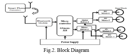
V. BLOCK DIAGRAM
VI. WORKING
The project will explore the development and management of the Omni-directional airport, which is a mobile platform capable of driving in all directions without restriction. This platform will be used for independent applications as well as for testing mobile-manipulator applications. In addition, the software that works on this platform will be re-tested so that the robot can easily adapt to many different applications.
- In project activities the legs are replaced by Omniwheel, an Omni-wheel robot built and tested in a smooth surface. For the purpose of even terrestrial gravity and to move smoothly in an empty space, we select a path in which the surface of the robot will remain in contact with the ground and the robot will align with the slope.
- In this system, the PWM signal is used as an input to the ATmega-328P digital anchors. level of freedom.
- Consistently DC Motors rotate and there is a nexus on the omni-wheel. Here we use language C to regulate the movement of the fuel wheels. The image below shows a drawing of the Base Robot movement block.
- Through surveillance and transport the robot will operate on its own terms.
- The project will explore the development and management of the Omni-directional airport, which is a remote area capable of driving anywhere without restrictions. This platform will be used for standalone applications as well as for remote-manipulator testing applications.
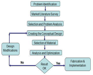
VII. METHODOLOGY
A. Components
- Atmega 328 P
- Control Board Platform
- Battery
- Omni wheels
- RF module
- LCD Display
- Adapter
- Motor Driver
- DC Motor
- Power supply board
- Frame
- Wireless Camera
- Others
B. Software
- Arduino Compiler
- MC Programming Language: C
VIII. COMPONENTS SPECIFICATION
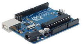
A. Arduino Uno (12v)
?rduin? Un? is ?n ??en s?ur?e mi?r???ntr?ller b??rd b?sed ?n the mi?r??hi? ?Tmeg?328? mi?r???ntr?ller ?nd devel??ed by ?rduin?.??. The board is equipped with sets of digital anchors and analog input / output (I / O) that can be connected to various extension boards (shields) and other regions.
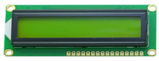
B. LCD Display
Liquid crystal display (LCD) is a small, flat panel used to display computer information such as text, pictures, and moving pictures. The LCD represents the Liquid Crystal display. The LCD gets a wide range of replacement LEDs (seven-segment LEDs or more segmented LEDs). 16 * 2 LCD display.
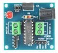
C. Motor Driver
The driver of the car is a current amplifier, the performance of motorists to hold the low current control signal and convert it into a high current signal that can use the engine.Fee2 is the controller for L298 Motor.
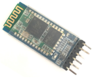
D. Bluetooth Module
HC-06 Technical Specifications
- Bluetooth serial mod for Arduino and other sub-controls
- Active power: 4V to 6V (Normal + 5V)
- Current Performance: 30Ma
- Distance: <100m
- Works with Serial communication (USART) and compatible TTL
- Adheres to IEEE 802.15.1 standard protocol
- Uses Frequency-Hopping Spread spectrum (FHSS)
- Can work with Master, Slave or Master / Slave mode
- Can be easily connected to Laptop or Mobile Phones via Bluetooth
- Supported baud rate: 9600,19200,38400,57600,115200,230400,460800.
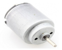
E. Dc Motor
An robot is an electromechanical sleight that responds to space in one way or another. Decisions and actions taken by its autonomy to perform a particular function. A robot is a man-made device whose movements are organized, organized, activated, modified, heard, and controlled.
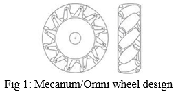
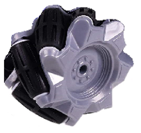
F. Omni Wheel
The basis of the Omni-directional vehicle (ODV) is that it has the ability to travel in any direction while maintaining a certain shape. To do this, a series of connections must be made of a trail that allows more than one traveler at a time. The performance of the Omni-Wheel robots affects functions such as, Even Control, Route planning etc. The above machines are designed for a variety of country conditions such as width, location and inclination.
IX. . ADVANTAGES
A. A circular robot has many advantages over remote-powered robots.
B. Unique circular robot design provides additional protection to the driving unit and additional stability.
C. The robot control system is different.
d. It moves everywhere.
X. . DISADVANTAGES
A. Few of them are expensive
B. It is difficult to use
C. It is difficult to control.
XI. RESULT & DISCUSSION
A. Design Problems
During the construction of the project, the team faced many challenges. These problems are::
- Omni-Directional Motion: The robot can travel to many places; right, left, front, back etc. So the wheels were important to produce all of this movement, then the robot needed something special the shape of the wheels because the wheels around the world cannot help making this movement. Mecanum the wheels are one of those wheels that can produce this movement..
- Wheel Design: The first problem that is addressed when designing a tire is choosing the number of rollers, because the load that the tire can carry depends on the number of rollers. Then the number of rollers that can achieve the desired goal of the robot is nine rollers. The second problem is the roller angle that allows you to connect the two flanges together, the angle that meets what you want is 22?.
- Carrying Mechanism: The robot carried a load of up to 150 kg. So it was necessary to have an engine with good torque with a high voltage of 24V, motors with these structures are wheel chair motors.
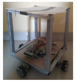
XII. PROJECT IMAGE
XIII. URE WORK
To improve the viewing angle the ultrasonic sensors will be placed in corners, over the wheels, instead of placed between the wheels. Converting h bridges into one that requires one PWM signal per vehicle.
In the near future work, Omni wheeled robots can be designed using a hydraulic piston that gives the robot extra power to perform mechanical work in the field. Robot wheels can be further developed to navigate winding and sloping terrain. Continuously the Omni-wheel robot platform can be designed to be sturdy to carry additional loads in the area. These types of robots are used in the military, industry and various other applications.
Conclusion
The development of the Omnidirectional vehicle was further enhanced by the efficient operation of this type of structure and the addition of a ground-moving vehicle platform that could move in an unusual way. Omni-directional vehicles are divided into two categories that describe the type of tire design they use: standard wheel designs and special wheel designs. Omnidirectional mobile robot with Mecanum wheels for educational purposes. The robot has full omnidirectional motion, thanks to its special Mecanum wheels. More information on common and special wheel designs, Mecanum tire design features and robots, kinematic models, and electrical and control techniques have been introduced. Because of its mobility skills and its versatility, the robot mentioned in this chapter can be used as an exciting learning platform.
References
[1] Ghariblu, H. \"A new mobile ball robot-dynamic modeling and simulation.\" Applied Mathematical Modelling 39, no. 10 (2015): 3103- 3115. [2] Chen, Wei-Hsi, Ching-Pei Chen, Jia-Shiuan Tsai, Jackie Yang, and Pei- Chun Lin. \"Design and implementation of a ball-driven omnidirectional spherical robot.\" Mechanism and Machine Theory 68 (2013): 35-48. [3] Joshi, Vrunda A., Ravi N. Banavar, and Rohit Hippalgaonkar. \"Design and analysis of a spherical mobile robot.\" Mechanism and Machine Theory 45, no. 2 (2010): 130-136. [4] Halme, Aarne, Torsten Schönberg, and Yan Wang. \"Motion control of a spherical mobile robot.\" In Advanced Motion Control, 1996. AMC\'96- MIE. Proceedings., 1996 4th International Workshop on, vol. 1, pp. 259-264. IEEE, 1996. [5] Bicchi, Antonio, Andrea Balluchi, Domenico Prat Tichizzo, and Andrea Gorelli. \"Introducing the “SPHERICLE”: an experimental testbed for research and teaching in nonholonomy.\" In Robotics and Automation, 1997. Proceedings., 1997 IEEE International Conference on, vol. 3, pp. 2620-2625. IEEE, 1997. [6] Camicia, Carlo, Fahio Conticelli, and Antonio Bicchi. \"Nonholonomic kinematics and dynamics of the sphericle.\" In Intelligent Robots and Systems, 2000 (IROS 2000). Proceedings. 2000 IEEE/RSJ International Conference on, vol. 1, pp. 805-810. IEEE, 2000. [7] Mojabi, Puyan. “Introducing August: A Novel Strategy for an Omnidirectional Spherical Rolling Robot.” In Robotics and Automation, 2002. Proceedings. ICRA’02. IEEE International Conference on, vol. 4, pp. 3527-3533. IEEE, 2002. [8] Zhan, Qiang, Yao Cai, and Caixia Yan. \"Design, analysis and experiments of an omni-directional spherical robot.\" In Robotics and Automation (ICRA), 2011 IEEE International Conference on, pp. 4921- 4926. IEEE, 2011. [9] Kaba?a, Marek, and Marek Wnuk. \"Design and construction of RoBall, a spherical, nonholonomic mobile robot.\" (2004). [10] J. E. M. Salih, \"Designing Omni-Directional Robot With Mecanum Wheel,\" American Journal Of Applied Sciences, 2005.
Copyright
Copyright © 2022 Prof. A. V. Wanjari , Priti S. Mondhe, Naba Raza , Nikhil S. Meshram , Nikita U. Khante , Chandrashekhar Patil , Sharvari D. Bhajbhuje , Abhishek N. Panchbudhe. This is an open access article distributed under the Creative Commons Attribution License, which permits unrestricted use, distribution, and reproduction in any medium, provided the original work is properly cited.

Download Paper
Paper Id : IJRASET40875
Publish Date : 2022-03-20
ISSN : 2321-9653
Publisher Name : IJRASET
DOI Link : Click Here
 Submit Paper Online