

Ijraset Journal For Research in Applied Science and Engineering Technology
A Review on Study of Performance Assessment of Multistorey Building Subjected to Earthquake Using STAAD Pro
Authors: Abhishek Thigale, Sanil Kavalekar, Divya Deshmukh, Kirti Shirsath, M. N. Khade
DOI Link: https://doi.org/10.22214/ijraset.2022.41949
Certificate: View Certificate
Abstract
From the beginning of life on Earth it is evident that natural catastrophes cause a lot of destruction to human life and property. One of the major natural phenomena is the Earthquake. Sudden shaking of ground is a difficult challenge to any structure standing on earth. Due to Improper design of the structure without seismic resistance many buildings have collapsed, and lives have lost during earthquakes. Different shapes & materials of buildings have been used to achieve the strength required to withstand the earthquake. In modern era, lots of seismic force resisting techniques are being used to make a structure/building earthquake resistant. These techniques include introducing Shear walls. to enhance the structure. In this paper, I present a Comparative analysis of earthquake resisting techniques on a multi storey building with the help of different types of Shear walls and using software. The comparison is done between an un-Resisting structure, parallel shear walls, L-shaped shear wall, diagonal bracings, X-shaped bracings & V shaped bracings. The use of shear walls helps to strengthen then structure to make it more Earthquake resistant. The analysis in done on a G+10 building for seismic zone III as per IS 1893:2002 codal provisions. The software that I have used to carry out this analysis is Staad pro v8. It is found out that shear walls contribute largely in reducing the deflection by increasing the strength and stiffness of the building. The results of this project can further be used to enhance the seismic strength of buildings using combination of seismic resistance techniques.
Introduction
I. INTRODUCTION
An Earthquake is Earth’s Shaking or in other words release of energy due to the movement of tectonic plates. This can be destructive enough to kill thousands of people and bring huge economic loss. This natural disaster has many adverse effects on earth like ground shaking, landslides, rock falls from cliffs, liquefaction, fire, tsunami etc. Buildings are highly affected by an earthquake, and in some cases, they are shattered down to the ground level. When the ground shaking occurs beneath the building’s foundations, they vibrate in an analogous manner with that of the surrounding ground. The inertia force of a structure can develops shearing effect on it which in turn causes stress concentration on the connections in structure and on the fragile walls. This results in partial or full failure of structure. The excitement and prevalence of shaking depends on the orientation of the building. High rise structures have the tendency to magnify the magnitude of long-time periodic motions when comparing to the smaller one. Every construction has a resonant prevalence which are the characteristics of structure. Taller buildings have a tendency for long time periods than shorter one which make them relatively more susceptible to damage. Hence, one must be careful while performing the analysis of a tall structure. To analyses a tall structure many analysis procedures are valid like a) Equivalent static analysis, b) Response spectrum analysis, c) Linear dynamic analysis, d) Nonlinear static analysis or nonlinear pushover analysis and e) Nonlinear dynamic analysis. Soil structure interaction analysis is also essential to be considered. After identifying the soil type, analyzing procedure is selected to do the detailed analysis of the interaction between soil and structure. To reduce the seismic effects on tall buildings several equipment is used like dampers or base isolation process. In dampers viscous damper, friction damper, yielding damper, magneto rheological fluid dampers tuned mass damper or harmonic absorber can be used. In base isolator magneto rheological elastomer, elastomeric bearing system, sliding system can be used.
II. OBJECTIVES
- To describe the concept of eccentricity with reference to buildings subjected to lateral forces, such earthquakes.
- To study the effect of stiffness of infill walls on the behavior of the structure when subjected to seismic.
- To determine the collapse strength of the symmetric and asymmetric building models.
- To observe the level of change of internal forces computed with increased eccentricity compared to symmetric.
III. LITERATURE REVIEW
- Aziminejad and Moghadam [2009] observed that the experience from the performance of buildings during past earthquakes has shown that asymmetric buildings often sustain more extensive damage as compared to symmetric buildings. Performance of an asymmetric building can be quantified by responses such as rotation of the floors, the maximum drift of flexible and stiff edges of the buildings or the ductility demand of the elements on the edges. In their study, the nonlinear dynamic behavior of a set of five story asymmetric buildings with different strength distribution strategies was considered. To show different responses such as drift, ductility and plastic hinge rotation of the models, fragility curves are used. The results show that among torsionally rigid models studied, models with a smaller strength eccentricity perform better. However, in general, the optimum strength eccentricity is shown to be a function of the selected damage index
- Shahzeb Khan, Vishal Yadav, Sandeep Singla: Earthquake Resisting Techniques on A G+5 Storey Building with the Help of Shear Walls using Software: In this paper, I present a Comparative analysis of earthquake resisting techniques on a G+5 story building with the help of different types of Shear walls using software. The comparison is done between an un-Resisting structure, parallel shear walls, L-shaped shear wall, diagonal bracings, X-shaped bracings. The use of shear walls and bracings helps to strengthen then structure to make it more Earthquake resistant. The analysis in done on a G+5 building for seismic zone III as per IS 1893:2002 codal provisions. The software that I have used to carry out this analysis is Staad pro v8. It is found out that shear walls and bracing contribute largely to reducing the deflection by increasing the strength and stiffness of the building. The results of this project can further be used to enhance the seismic strength of buildings using combination of seismic resistance techniques.
IV. METHODOLOGY
This study has been undertaken as systematic literature review (SLR) to collect the data and results from previous study. It will explain more about the preferred required report paper. There are three phases will be focus on such as identification screening and eligibility process. As it obvious that our main reason for this research is too aware and improve the awareness of people toward this destructive phenomenon, which is Earthquake, so concerning this issue we’ve decided to make research regarding new technologies for constructing Earthquake resistant structures, which was Started from a simple idea from local building projects, then we started to search and mention new ways which the world is using right now.
A. Methodology to Undertake analysis and Design of g+5 Building on stadd. Pro
Design On Staad Pro. Software
- Step-1: Draw the Plane and Nodal point generation. With respect to the positioning of the column on the building plan we, respective nodal points have been entered on the STADD model.
- Step-2: Beam and column representation Based on the nodal points, with the help of add beam command on STADD. Pro, beam, and columns have been generated.
- Step-3: Assign support and member property provided below every column as fixed supports Subsequently, based on load calculations, the beam and column cross-sections have been assigned.
- Step-4: 3D View After assigning the member property, the 3D view of the structure can be shown.
- Step-5: Dead Load assignment According IS: 875 (Part 1) – 1987, the dead loads have been assigned based on member load, floor load and self-weight of the beams.
- Step-6: Live Load assignment According to IS: 875 (Part 2) – 1987, live load of 2KN/m2 has been assigned to the members.
- Step-7: Seismic load assignment After creating suitable seismic definition as per the requirement of IS 1893 (Part 1): 2002, the seismic load has been assigned with respect to +X, -X, +Z and -Z directions with appropriate seismic factor.
- Step-8: Wind load assignment After entering the wind intensity and creating the wind definition as per IS: 875 (Part 3) – 1987, the wind loads have been assigned with respect to +X, -X, +Z and -Z directions.
- Step-9: Load combination assignment Different load combination cases have been assigned to the model based on specified loading combinations provided in the IS CODES that are also available in STADD. Pro.
- Step-10 Analysis of RCC Design. (IS CODE 456)
- Step-11: Structural Design on STADD. Pro and Output Generation.
The design is undertaken as per IS 456:2000. M25 concrete and FE415 is used as design parameters Percentage steel of 4% has been specified as per IS Code standards and the design parameters have been assigned to respective beam and column. After the final design of the structure, the output file is generated containing the structural design of every individual beam and column member.
B. Manual Calculations
- Step-1: Design Seismic Base Shear
The total design lateral force or design seismic base
shear (VB)along any principal direction shall
be determined by the following expression:
Vb = AhW
Where,
Ah = Design horizontal acceleration spectrum
value as per 6.4.2, using the fundamental
natural period T, as per 7.6 in the considered
direction of vibration, and
W =Seismic weight of the building as per 7.4.2.
- Step- 2: Design Lateral force
The design base shear (Vb) computed in shall
be distributed along the height of the building as per the following expression:
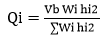
Where,
Qi = Design lateral force at floor i
Wi= Seismic weight of floor i,
hi = Height of floor i measured from base, and
n =Number of storeys in the building is the
number of levels at which the masses are located.
C. Analysis Techniques Used On Staad Pro
- Max Deflection: Max deflection can also be called the Top deflection of the structure. It is the maximum extent to which the structure displaces in X & Z direction under earthquake loads in both perpendicular directions.
- Story Drift: Story displacement is the absolute value of displacement of the storey under action of the lateral forces.
- Story Shear: The design seismic force to be applied at each floor level is called storey shear.
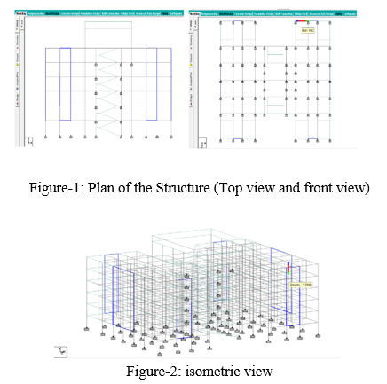
D. Building Modelling
General
In this project I have used is a G+5 storey building with same floor plan with 9 bays having along longitudinal and 6 bays in transverse direction as shown in figure. This building is designed as per the Indian Code of Practice for Seismic Resistant. Design of buildings story heights of buildings are assumed to be constant including the ground story. The buildings are modelled using software “STAAD-PRO V8i 3.1 Dimensions.
Input Data
- Type of structure: multi-storey fixed jointed plane frame.
- · Number of stories 6 (G+5).
Floor height 3 m.
Seismic zone III (IS 1893 (part 1):2002).
Materials Concrete (M 35) and Reinforcement (Fe415).
Column 600 x 250 mm (for all columns).
Beam 230 x 450 mm (for all beams).
Type of soil = Hard soil.
Response spectra as per IS 1893.
E. Loading Details
Dead Load (as per IS part I)
Slab Thickness Assume = 150 Mm.
Self-Weight = 1 Kn/M2
Wall Load (External Amd Internal) = 12.04 Kn/M2
Parapet Wall Load = 4.416 Kn/M2
Floor Load = 3.125 Kn/M2
Live Load (as per IS 875 part II)
Floor Load = 2 Kn/M2
Floor Load On Roof = 0.5 Kn/M2
Plate Load (Staircase) = 3 Kn/M2
Plate Load (Water Load At 23.5 M Height) = 15Kn/M2
Wind load as per IS 875 part III
Intensity = 0.68 Kn/m2
Height = 10m
Intensity = 0.76 Kn/m2
Height = 15m
Intensity = 0.85 Kn/m2
Height = =20m
Intensity = 0.95 Kn/m2
Height = 23.5m
Seismic Load
Zone IIIs
Zone Factor = 0.16
Earthquake Resistance Design of Structure = IS 1893 (Part 1) 2002
Response Reduction Factor = 5
Importance Factor = 1.5
Damping ratio = 0.05
Load combinations as per IS 875 Part V
Auto generated as per is code.
F. Analysis
Analysis of building is one using STAAD Pro. The models were prepared in the STADD Pro. Software by using different types of RC shear wall viz. Parallel Shear wall and these are located at different location such as along periphery.
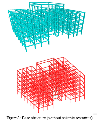
Base Structure (without shear wall)
A base structure is modelled only with the use of columns and beams, and no additional seismic restraints are used. This the plain or base structure that will be further used for comparison with other models with additional seismic restraints. The following structure is a G+5 story building designed on staad pro having no seismic restraints.
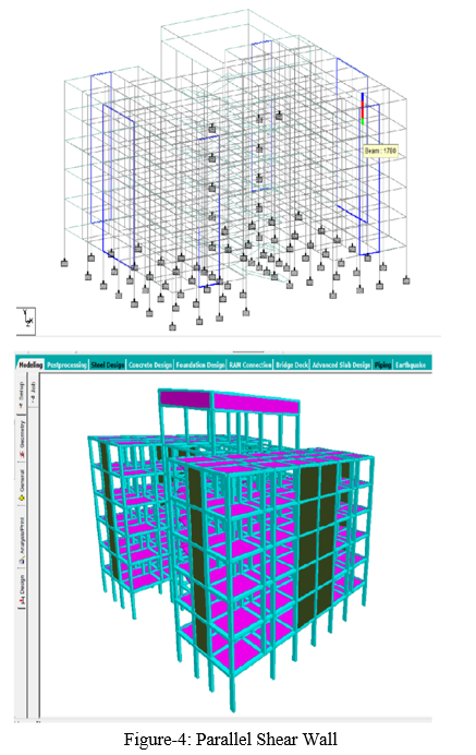
G. Parallel Shear Walls
Model is prepared using staad pro software where the high-rise structure is embedded & supported with shear wall on all six sides. As the Shear walls are in parallel direction with respect to the two directions of earthquake EQX &EQZ, it is names as Parallel Shear walls.
V. RESULTS
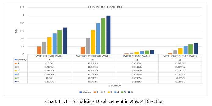
A. Lateral Displacement
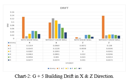
B. Story Drift
Conclusion
1) For RC framed model have been observed and analysed by introducing various earthquake resisting members, like: Parallel shear walls. 2) It is observed from the above analysis that the displacement observed in the models, which are without shear walls is more as compared to the models having shear walls at different locations. 3) It has been observed that the Max deflection is significantly reduced after providing the shear walls in the RC frame in X-direction as well as in Z-direction. 4) It has also been observed that Story shear effectively decreased by introducing Shear Walls. 5) The best location of shear wall in multi-storey building is parallel shear walls. 6) The least story shear is found in the model with shear wall. The shear force is maximum at the ground level & the bending moment is maximum at roof level. 7) By providing shear walls to the high-rise structure, seismic behavior will be affected to a great extent and the stiffness, and the strength of the buildings is increased. 8) Finally, it is concluded that, optimization using shear wall is the best procedure, in present work mode for maximum earthquake resistance. Hence, it is finally concluded from all the above results that, shear wall and bracing system in the structure is more resilient in the event of the earthquake. From deflection point of view in high rise building shear wall structure is more suitable
References
[1] IS: 1983(Part 1): 2002: Indian Standards Criteria for Earthquake resistance Design of Structures: Part 1 General Provisions and Building [2] Duggal, S. (2007). Earthquake Resistant design of Structures. Oxford University Press, USA [3] Sreeram, K & Singh, Rajendra Prasad & Siva, S & Siva Bhanu Sai Kumar, Sripathi. (2018). Effective location of shear walls and bracings for multi-storeyed building. [4] Maheri, Mahmoud &Sahebi, A. (1997). Use of steel bracing in reinforced concrete frames. Engineering Structures. [5] Reinforced concrete design ISO: 456-2000 [6] Anshuman. S “Solution of Shear Wall Location in Multi- JOURNAL OF CIVIL AND STRUCTURAL ENGINEERING Volume 2, No 2, 2011. Storey Building” INTERNATIONAL [7] International Journal of Innovative Technology and Exploring Engineering (IJITEE) ISSN: 2278-3075, Volume-9 Issue-2, December 2019
Copyright
Copyright © 2022 Abhishek Thigale, Sanil Kavalekar, Divya Deshmukh, Kirti Shirsath, M. N. Khade. This is an open access article distributed under the Creative Commons Attribution License, which permits unrestricted use, distribution, and reproduction in any medium, provided the original work is properly cited.

Download Paper
Paper Id : IJRASET41949
Publish Date : 2022-04-28
ISSN : 2321-9653
Publisher Name : IJRASET
DOI Link : Click Here
 Submit Paper Online