

Ijraset Journal For Research in Applied Science and Engineering Technology
Planning and Designing of Bus Terminal in Pattambi
Authors: Aabitha M, A.Ashin Ashraf, Akshay K, Devika R
DOI Link: https://doi.org/10.22214/ijraset.2023.53928
Certificate: View Certificate
Abstract
Introduction
I. INTRODUCTION
A. General
Pattambi is a town located in the banks of Bharathapuzha river. Pattambi is well connected with all major cities in Kerala. State Highway 23 joints state Highway 39 at Pattambi. Palakkad Ponnani road connects with NH66 also passes through the town. Pattambi-Cherpulashery road connects to state Highway 53 and further to National Highway 966. Pattambi is served by Pattambi railway station with 33 halting trains. The city has a population growth from 24,168 (2001 census) to 28,632 (2011 census). Due to population growth and the above reasons the city areas get congested. During rainy season the area get flooded. This creates difficulty to both human in terms of transportation as well as their daily living conditions. The present bus terminal in Pattambi is highly congested due to lack of space and high traffic in the bus terminal. A bus terminal/terminus where a bus route starts or finish, where vehicles stop, turn or reverse, and wait before start their journey /return journeys. It's also where passengers board.Reliable, safe and comfortable public transport systems are a precondition for developing sustainable transport systems. Bus systems, in particular, are extremely relevant since they form the majority of public transport trips. Improved bus services and developing state of- the-art supporting infrastructure like bus terminals, depots and bus stops can attract users and increase ridership. Public transport holds centre stage in the urban transport agenda. A well-functioning and sustainable city cannot be achieved without strengthening its public transport system.
The improvement of the town or the city is very essential in this situation. This arises the need ofthis project. This increases the demand for public transport services and facilities. This has subsequently led to challenges to provide suitable bus terminals. The Municipalities are keen to provide good public transport but have difficulties providing the needed space. A comprehensive study is therefore undertaken including literature review, field studies and modelling of the capacity of different types ofbus stops and bus terminals. The city is growing and the demand for land in the central region as well as public transport facilities is increasing. As a result, it has become a big challenge to plan and build the needed terminals. The existing bus station lacks basic facilities and poses serious traffic congestion problems due to the entry and exit of buses, which accelerate the traffic block in road. By taking these problems into consideration, it has been decided to shift the bus stand to a new proposed site.
Infrastructure plays a vital role in the operation of an efficient, convenient and safe transit system (Trans Link Transit Authority 2011). When a transits infrastructure is designed to enhance passenger experience, its attractiveness is ensured, making it a viable alternative to private motorized transport. The National Urban Transport Policy (NUTP) (MOUD 2006) recognizes that city dwellers are of utmost importance and that all plans must be centered on their common benefit. This project is proposed toprovide adequate, economical, efficient, reliable, comfortable, safe and environment-friendly modern passenger transport services for the people and to provide affordable, safe and sustainable passenger transport services to the public. For future consideration of modern infrastructure in bus terminal, should be implemented to increase its lifespan and public rush & more revenue generation can be achieved.
In all spheres of human life buildings are always necessary to satisfy human need. This study mainly focuses on the planning and design of an assembly building i.e Pattambi bus terminal. The bus terminal functional planning concepts is in AutoCAD and 3D modelling preparation using Revit architecture or using 3Ds Max and Lumion. As the size of a population increases, so does its energy consumption. It has been suggested that the size of the population the planet is able to sustain depends on the amount of energy sources available. Thus, it is important to save energy. This bus terminal is constructed in such a way that it generates renewable energy from its respective renewable sources. It is very important to reduce pollution due to current situations arising in the world. This bus terminal is made of environmentally friendly materials which helps in pollution control, thus making this bus terminal environment friendly. We are not using any from outside, the energy is produced with in the terminal mainly two sources of energy with in the terminal are solar energy production about of 120kW and an energy production from speed breaker generators.
The speed breaker generator works on the principle that when a bus goes through the speed breaker it compresses or moves downward and regains its original position, by this motion it rotate the generator with the help of gears.
Instead of using normal bitumen road, the study area utilizes the mix of bitumen and plastic roads which last more duration than the normal road inside the bus terminal. Various kinds of tests were conducted to check qualities of plastic and bitumen over traditional bitumen roads. Construction of this kind roads is good method to manage plastic waste. Other features like waiting area, toilets, dining area, workshop for buses,taxi stand, electric charging spot, petrol pump. The construction is planned in a way that the bus terminalhas a good landscape.
B. Aim
The main aim of the project is t o plan and design of bus terminal at Pattambi using eco-friendlymaterials and a model of speed break power generator.
C. Objectives
The main objectives of the project are as follows:
- To conduct reconnaissance survey and identification of the present scenario.
- To apply the functional planning concepts and drawing of the bus terminal in AutoCAD and 3D modelling preparation using 3Ds Max and Lumion.
- To conduct test of bitumen and combined bitumen-plastic material for roads in bus terminal.
- To prepare a model of speed breaker power generator for energy saving.
- To carry out the installation of solar panel and rain water harvesting system.
D. Scope And Limitation
The following are the scope for further studies:
- The installation of solar panel can be extended to the whole area to sell extra energy to KSEB.
- Design and estimation of electric charging port in future.
- Installation of petrol pump for private buses.
- Due to the financial aid and time constraint, the project is limited to the rough estimation of bus terminal,3D modelling and preparing a model of the speed breaker power generator with the ability to generate electricity.
II. LITERATURE REVIEW
Ashwin et al. (2020) had conducted the work which is helpful for the bus travelers to utilize all the amenities within the bus stop. The solar and turbine energy bus stop is monitored by city officials throughcamera sensors. Solar and turbine energy to produce better lighting features within the bus shelter and to recharge electric vehicles. Interactive touch screen to show the bus number and route map of each buses destinations. Sensor based toilet provides comfortable and cleanliness environment within the bus shelter. This work will be implemented in Salem metropolitan area bus stops. In future, this work will act as a power house to recharge the electric vehicles everywhere else. This work distinguishes seven noteworthy objectives in outlining a decent solar powered vitality transport stop: wellbeing, warm solace,vitality comfort, wind security, visual solace, openness, and coordination.
Kalpana & D. Surendaran. (2018) emphasized that coating plastic over aggregates shows a better performance in roads compared to conventional roads. The study showed that the aggregate impact value, aggregate crushing value and specific gravity for plastic coated roads increases and water absorption decreases which are all good signs for the development in the strength of the plastic-coated roads compared to the conventional roads, the weight of the plastic to be added. Plastic road would be a blessing for India. In hot and extremely humid climate durable and ecofriendly plastic roads are of greatest advantages. This will also help in saving the earth from all type of plastic waste.
Ali Azam et al. (2020) identified that some limitations as opportunities for future research, in subjects such as the viability and economic profitability of more advanced projects, With the helpof speed breaker mechanism, linear motion is converted into rotary motion of pinion and thus is used to rotate the shaft of DC generator and will be able to use batteries power for other useful applications.It can also be implemented on the roads. The generated power can be used for the domestic purpose or commercially, which are present near the speed breaker, changing world and thirsty for new options, which are viable and whose impact be as small as possible.
S. Logeswaran et Al. (2021) monitored the review analysis of factors influencing the design of bus station. The model discussed in the paper helps the traffic assigners to enable the calculation forbay loading rate dwell time comparisons in bus terminals. The bus terminal elements suffer due to irregular pattern of flow of buses but in case of depot due to change in alignment of location of bus maintenance and its actual duration it leads to queue formation. In order to avoid the concept of mis- alignment the factor sectorial bus pattern has to be followed. The regional sector helps the drivers to flow a mean free space path.
S. Logeswaran (2017) enhanced the review analysis of factors influencing the design of bus station. A bus station is a large structure than bus stop for boarding and dropping off the passengers or Bus terminus is a public area from where bus starts or ends its scheduled routes. It serves for the public for bus transportation. The size of the terminus can be decided by analyzing its operational conditions, bus routes, scheduled timings and basic facility requirements. Bus terminus are provided with other facilities such as shopping complexes, toilet, drinking water, restaurant, hotels, water treatment plant, auto stand, taxi stand, shopping malls. This paper explains the design factors and design elements to be considered for the bus terminus plan with the minimum standards.
O. Yebanjo O. O et Al. (2021) studied the analysis of innovative bus stop shelters, rainwater harvesting & storm water management in Nigeria. The study focused on water conservation through water harvesting and management of storm water in peri urban of Abeokuta, South Western Nigeria. The study area frequently experiences flooding during wet seasons due to failed and non-existence drainage systems for the channeling of the storm water, and acute water shortage during period of dry season due to the nature of the hydrogeological environment; the basement complex.
A. Literature Outcome
Table 1: Literature Review
|
SL NO |
TITLE |
OBJECTIVE |
OUTCOME |
|||
|
1 |
Secure design for smart bus shelter using renewable energy. |
Discusses to construct a secure design for smart bus shelter by using renewable energy. |
The solar energy produces better lighting features within the bus shelter and to recharge electric vehicle, in the future this work will act as a power house to recharge the electric vehicles everywhere else. |
|||
|
2 |
Utilization of waste plastic in bituminous road. |
This study evaluates utilization of waste plastic in bituminous roads. |
Using plastic waste in mix will help reduction in need of bitumen by around 10% increase strength and performance of road. It is economical way to reduce the number of resources used for construction. |
|||
|
3 |
Speed Breaker Power Generator |
An experimental study to generate the electricity by SBPG is described in this paper. When a car reaches on the speed breaker, the rack moves downward to generate linear to rotary motion using pinions. The rotary motion is transferred to DC generator which generates DC power which is stored in batteries same as in solar technology |
With the help of speed breaker mechanism, linear motion of rack is converted into rotary motion of pinion and thus is used to rotate the shaft of DC generator. DC voltages charge the batteries during the passage of moving vehicles. Using inverter (DC to AC conversion), we will be able to use batteries power for other useful applications. It can be implemented on the toll plazas, highways. Guide slots andlubricating oil sump is required to minimize friction losses. |
|||
|
4 |
Review analysis on Factors influencing the design of bus station. |
Analyzing on factors influencing the design of bus station. |
The model discussed in this review helpsthe traffic assigners to enable the calculation for bay loading rate dwell time comparison in bus terminals. |
|||
|
5 |
Design standards for planning a bus terminus |
This paper explains the design factors and design elements to be considered for the bus terminus plan with the minimum standards. |
This journal consists of the design factors and minimum standards for the bus terminal. The design factors and standard width of the entrance and exit of the bus terminal are obtained from the journal |
|||
|
6 |
Analysis of innovative bus stop shelters, rainwater harvesting, stormwater management in Nigeria |
Aim to build an innovative bus stop shelter, rainwater harvesting, stormwater management in Nigeria. |
The study focused on water conservation through water harvesting and storm management. |
|||
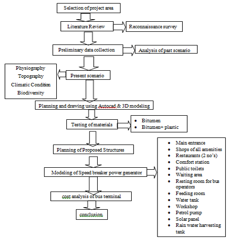
III. METHODOLOGY
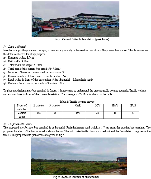
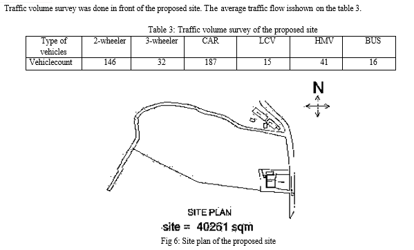
IV. EXPERIMENTAL INVESTIGATION
A. General
Transportation network is the main infrastructure which connects the important places in a state and district. Safe movement and comfort of passenger is a vital factor in a transportation network. Now a days, the world is facing the pollution and destruction of the environment caused by the plastic. The recycling process for plastic can be very expensive, thus can use the plastic waste to construct roads by mixing with the bitumen. So that the defects in the pavement can be avoided to some extent by increasing the strength of the road, reducing road fatigue and gets better resistance towards rainwater and cold weather. Thus, the amount of plastic strewn around will definitely reduce.
B. Study Area
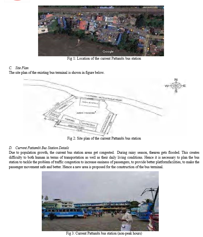
The study area selected for the project work is Pattambi. Pattambi is a fast-growing town, the population of the Pattambi municipality is 28,632 as per census 2011. The existing bus terminal is not enough to cope up with this traffic volume. During rainy season the area get flooded. This creates difficulty to both human in terms of transportation as well as their daily living conditions. The presentbus terminal in Pattambi is highly congested due to lack of space and high traffic in the bus terminal.
E. Physiographical Characteristics
- Climate
Pattambi’s climate is classified as tropical. Most months of the year are marked by significant rainfall.The short dry season has little impact. The climate here is classified as AM by the KöppenGeiger system.
The average annual temperature is 27.6 °C in Pattambi. About 2749 mm of precipitation falls annually. A tan average temperature of 30.0°C, April is the hottest month of the year. The lowest average temperaturesin the year occur in July, when it is around 25.6 °C. Precipitation is the lowest in January, with an averageof 1 mm. The greatest amount of precipitation occurs in July, with an average of 718 mm.
2. Topography and physiography
The physiographical details of the study area are given below:
a. Topography of Pattambi
b. Locality: Pattambi
c. Latitude: 10.806784
d. Longitude: 76.196485
e. Time zone: Asia/Kolkata UTC +05:30
f. Region 1: Kerala
g. Region 3: Palakkad
h. Elevation: 45 meters/147.64 feet.
F. Tests On Bitumen
Plastic plus bitumen pavement is used for the construction of roads in the bus terminal. The bitumen grade used here is VG 30 and the bitumen is mixed with shredded Plastic (poly propylene) which is 10% weight of the bitumen. Plastic-bitumen composite roads have better wear resistance than standard asphalt concrete roads. They do not absorb water, have better flexibility which results in less rutting and lessneed for repair. Road surfaces remain smooth, are lower maintenance, and absorb sound better. The waste plastic is shredded & coated over aggregate & mixed with hot bitumen and resulted mix is usedfor pavement construction.
This will not only strengthen the pavement and also increases its durability. Plastics-waste is coated over aggregate. This helps to have a better binding of bitumen with the plastic- waste coated aggregate which leads to increased bonding and increased area of contact between polymer and bitumen.
The polymer coating also reduces the voids. Plastic-bitumen composite roads have better wear resistance than standard asphalt concrete roads.
They do not absorb water, have better flexibility which results in less rutting and less need for repair. Road surfaces remain smooth, are lower maintenance, and absorb sound better. According to the World Economic Forum, plastic roads have been proven to be three times stronger than asphalt. This means they can stand up to harsher weather and be more resistant to potholes, making them significantly more durable.
The following tests are conducted both with bitumen with plastic and bitumen without plastic.
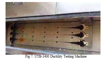
- Ductility Test
The property of bitumen which allows it to undergo deformation or elongation is called ductility of bitumen. The ductility of bitumen is measured by the distance in cm (centimeter), to which the bitumen sample will elongate before breaking when it is pulled by standard specimen at specified speed and temperature.
Procedure
a. Melt the bituminous test material completely at a temperature of 75oC to 100oC above the approximatesoftening point until it becomes thoroughly fluid.
b. Strain the fluid through IS sieve 30.
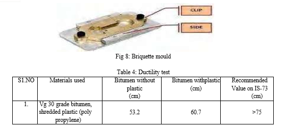
c. After stirring the fluid, pour it in the mould assembly and place it on a brass plate
d. In order to prevent the material under test from sticking, coat the surface of the plate and interior surfaceof the sides of the mould with mercury or by a mixture of equal parts of glycerin and dextrin.
e. After about 30 – 40 minutes, keep the plate assembly along with the sample in a water bath. Maintainthe temperature of the water bath at 27oC for half an hour.
f. Remove the sample and mould assembly from the water bath and trim the specimen by leveling thesurface using a hot knife.
g. Replace the mould assembly in water bath maintained at 27oC for 80 to 90 minutes.
h. Remove the sides of the moulds.
i. Hook the clips carefully on the machine without causing any initial strain.
j. Adjust the pointer to read zero.
k. Start the machine and pull two clips horizontally at a speed of 50mm per minute.
l. Note the distance at which the bitumen thread of specimen breaks.
m. Record the observations in the proforma and compute the ductility value report the mean of two observations, rounded to nearest whole number as the “Ductility Value. This same procedure is followed in the case of bitumen with shredded plastic.
2. Softening Test
The softening point of bitumen or tar is the temperature at which the substance attains a particular degree of softening. As per IS:334-1982, it is the temperature (in o C) at which a standard ball passes through a sample of bitumen in a mould and falls through a height of 2.5 cm, when heated under water or glycerin at specified conditions of test. The binder should have sufficient fluidity before its applications in road uses. The determination of softening point helps to know the temperature up to which a bituminousbinder should be heated for various road use applications. Softening point is determined by ring and ball apparatus.
Procedure
a. Preparation of test sample: Heat the material to a temperature between 75-100 0 C above its softening point stir until, it is completely fluid and free from air bubbles and water. If necessary, filter it through IS Sieve 30. Place the rings, previously heated to a temperature approximating to that of the molten material, on a metal plate which has been coated with a mixture of equal partsof glycerin and dextrin. After cooling for 30 minutes in air, level the material in the ring by removing the excess with a warmed, sharp knife.
b. Assemble the apparatus with the rings, thermometer and ball guides in position.
c. Fill the bath with distilled water to a height of 50 mm above the upper surface of the rings. The starting temperature should be 5OC. Note: Use glycerin in place of water if the softening pointis expected to be above 80 o C the starting temperature may be kept 35 o C.
d. Apply heat to the bath and stir the liquid so that the temperature rises at a uniform rate of 5±0.5o C per minute.
e. As the temperature increases the bituminous material softens and the ball sinks through the ring, carrying a portion of the material with it.
f. Note down the temperature when any of the steel ball with bituminous coating touches the bottomplate.
g. Record the temperature when the second ball also touches the bottom plate. The average of the two readings to the nearest 0.5 o C is reported as the softening point. This same procedure is followed in the case of bitumen with shredded plastic.
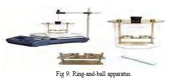
Table 5: Softening test
|
S1.NO |
Materials used |
Bitumen without plastic (°C) |
Bitumen with plastic (°C) |
Recommended Value on IS-73 (°C) |
|
1. |
Vg 30 grade bitumen, shredded plastic (poly propylene) |
42.5 |
47.4 |
40 |
Table 6: Comparison of Test Results
|
S1. No |
Tests |
Test result for bitumenwithout plastic |
Test result for bitumenwith plastic |
Recommended value on IS-73 |
Unit |
|
1 |
Softening |
42.5 |
47.4 |
40 |
C |
|
2 |
Ductility |
53.2 |
60.7 |
>75 |
cm |
3. Results
This comparison of test result can confirm that the strength of bitumen mixed with plastic is greater than the strength of bitumen without mixes of plastic. Using plastic waste in mix will help reduction in need of bitumen by around 10% increase strength and performance of road. It is economical way to reduce the number of resources used for construction.
V. PLANNING CONCEPTS OF BUS TERMINAL AND DESIGN OF SPEEDBREAKER POWER GENERATOR
A. Planning Criteria For Bus Station
In general, the four basic planning criteria for planning of terminals are –
- Need: Need of the terminal arises with increase in the demand. An organized bus terminal should meet the following requirements Accessibility.
a. Comfort and convenience.
b. Safety.
c. Easy processing.
2. Size: The following factors are considered to characterize the size of the terminal and its functions.
a. Flow of traffic.
b. System characteristics.
c. User characteristics.
3. Location: The selection of the location should satisfy the following criteria.
a. It should form a component in the hierarchy of transport systems.
b. It should be a component in the hierarchical system of transportation terminals.
c. The concentration and dispersal costs should be minimum.
d. It should be located such that as point of coordination and integration between inter-city and intra-city transport
4. Design: Following points should be kept in mind for efficient workability of terminal.
a. Segregation of bus and non-bus traffic.
b. Segregation of pedestrian and vehicular movement.
c. Elimination of vehicular traffic conflict.
d. Segregation of pedestrian flows.
e. Minimum processing for the buses.
f. Segregation of transportation and no-transportation activities.
B. Other Factors
The planning details are taken from KMBR
- Shop: The shops to be provided depend on the passenger capacity
- Sight Distance: The eye level of a driver for safe riding of a bus or vehicles. It should not have anyobstructions. The obstruction height should not exceed 0.5’ from a driver’s eye level of 3.9’ high.
- Width of Main Road: Depends on the main road crossing the bus terminus the right and left turnmovement of vehicles can be improved.
- Site Selection: Choose a suitable location that is easily accessible, ideally located near major roads or highways, and has sufficient space for the bus terminal and associated facilities.
- Terminal Layout: Design the bus terminal layout to ensure smooth traffic flow and efficientoperations. The following standard dimensions can be considered:
a. Entry/Exit Points:
b .Width: Typically, 8 to 10 meters to accommodate buses and other vehicles.
c. Height: Sufficient clearance height to accommodate buses, usually around 4.5 to 5 meters.
6. Bus Bays
a. Length: Minimum of 15 meters to accommodate one standard-size bus.
b. Width: Typically, 3.5 to 4 meters, allowing enough space for bus maneuvering and passenger movement.
7. Bus Platform Length: The length of the bus platform should be sufficient to accommodatethe length of the longest buses expected to use the terminal. This can vary depending on the type of buses (regular, articulated, or double-decker) and should typically range from 12 to18 meters.
8. Internal Roadways
a. Width: Main internal roadways should be around 6 to 8 meters wide to accommodate bus movement in different directions.
b. Pavement: Ensure a smooth and durable pavement surface throughout the terminal area.
9. Pedestrian Walkways:
a. Width: Provide wide walkways for pedestrians, typically around 3 to 4 meters, to ensure ease of movement and safety.
b. Accessibility: Incorporate ramps, handrails, and tactile paving to ensure accessibility for individuals with disabilities.
10. Bus Platform Width: The width of the bus platform should allow for safe movement of passengers and vehicles. A minimum width of 3 to 4 meters is recommended to provide adequate space for passengers to alight and board buses comfortably.
11. Aisle Width: The aisle width between adjacent bus platforms should be wide enough to allow for easy pedestrian movement, especially during peak hours. A minimum width of 4 to 5 meters is generally recommended.
12. Buffer Space: Ample buffer space should be allocated between bus platforms to ensure safe maneuvering of buses. This space can also be used for queuing passengers and managing crowd flow. A minimum buffer space of 3 to 4 meters is advisable.
13. Facilities and Amenities: Include the following facilities within the bus terminal with appropriate dimensions:
14. Waiting Area: The waiting area for passengers should be spacious enough to accommodate the expected passenger flow during peak hours. Sufficient seating arrangements, shelters, and amenities should be provided. A minimum area of 1.5 to 2 square meters per passenger is typically recommended. or consider a minimum of 0.9 to 1.2 square meters of seating area per passenger.
15. Toilets: Allocate sufficient space for clean and hygienic toilets for both males and females. Consider separate facilities for individuals with disabilities.
16. Ticket Counters: Allocate an adequate area for ticket counters and ticketing operations, ensuring smooth passenger flow.
17. Passenger Amenities: Include amenities like information boards, passenger information systems, and digital displays for schedules and announcements.
18. Commercial Spaces: Allocate space for shops, cafeterias, and other commercial establishments within the terminal area.
19. Parking Areas: Designate parking areas for passengers' vehicles, considering adequate space and efficient traffic flow.
20. Landscaping: Incorporate green spaces and landscaping elements to enhance the aesthetics and provide a pleasant environment.
21. Circulation and Traffic Management: Ensure proper circulation and traffic management within the bus terminal by implementing the following:
22. Signage and Wayfinding: Install clear signage and wayfinding systems to guide passengers and drivers within the terminal.
23. Vehicle Movements: Plan for separate entry and exit points to avoid congestion and ensure smooth vehicle movements. Incorporate one-way traffic systems and dedicated lanes for buses and other vehicles.
24. Pedestrian Safety: Implement pedestrian crossings, pedestrian signals, and adequate lightingto ensure the safety of pedestrians.
25. Signage and Lane Markings: Use visible lane markings and signage to guide vehicles and prevent confusion.
26. Access Roads: Plan well-designed access roads to the bus terminal that can accommodate the movement of buses, taxis, and other vehicles safely. Consider the turning radius and width requirements for different types of vehicles.
C. Layout Factors
The factors affecting the layout of the bus terminus and the planning concepts are,
- Design Speed: Buses moving inside the bus terminus should travel at a speed lesser than the speed of adjacent. highway before entering into the respective platform. The design speed of the bus inside the terminal should be between 20kmph – 25 kmph.
- Platform Width: Platform bay width varies depending on the type of parking of buses in bays. For 45 and 90 degrees parking the platform width must be 100’ and 70’ respectively.
- Bay Width: Platform bay width includes width of the bus and clearance on both sides. In general, the width of the bus lies between 8.5’–9’. The clearance width varies from 0.4’–0.5’. The width of bay lies between 9’–10’.
- Passage width of Bay: The intermediate distance between departure bays and waiting bays is called passage width of platforms. It is provided for safe movement of public. The passage width should be at least 5’–10’ forconvenient and safe turning of buses. People can move easily with adequate space.
- Parallel Offset: The minimum offset between two adjacent buses while waiting in a platform is ensured. It must be at least 5’. The 5 feet is the minimum distance that are required for safety movement for the passengers and gives easy turning of the buses while entering or leaving the bay.
- Turning Radius of Bus: The turning radius means the turning curve of the buses from the platform for departing is called as turning radius of bus. The turning radius of 36’ length bus is 47.28 feet.
- Road width at Entrance and Exit: The road width may be defined as the width of the carriageway with or without medians. For 2 lane road, road width is 25’ and for four lane road, road width is 50’. For four lane road including Centre median, the road width varies from 51’-60’.
- Centre median width: The Centre median is placed at the Centre of a highway for opposite movement of vehicles or parallel movement of vehicles. The width of the median must be between 1’–10’.
- Basic amenities in bus terminus
a. Car Parking: Size of the parking depends upon the type of parking will provide at the given location. When the parking demand is high (>3000), automated car parking can be suggested.
b. Bike Parking: size of the parking depends upon the type of parking will provide at the given location. When the parking demand is high (>35000), automated bike parking can be suggested.
c. Toilet: Toilet is a common utility in public areas for both male and female. Toilet is also given for disabled people separately for both male and female.
d. Administrative Block: It is an area where bus related activities such as ticket counter, ticket verification point, help desk, reception, etc., are available. Apart from that, shopping malls, entertainment halls, lodges, food coats, jewellery shops, gift shops and some extra facilities also available. The concept of planning the administrative building should be given due importanceto avoid the unnecessary movements and congestion.
e. Dimension of Bus Depot and Sewage Treatment Plant: These are the secondary factors of a bus terminus which may or may not be provided inside the terminal area. For this study, it was considered that for the reduction of conflicts of bus depot should be provided. For utilizing the waste water from toilets and drinking, etc., the waste water treatment is necessary.
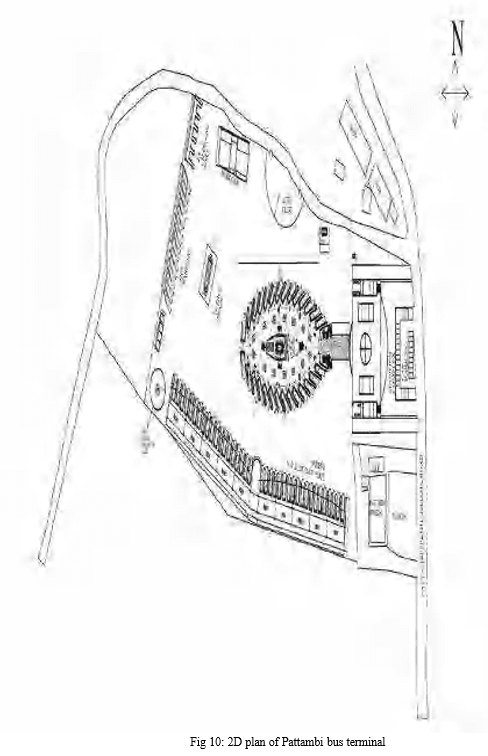
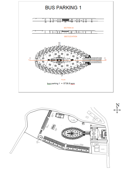
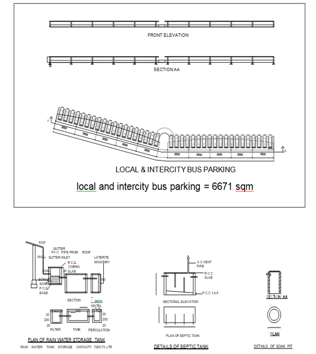
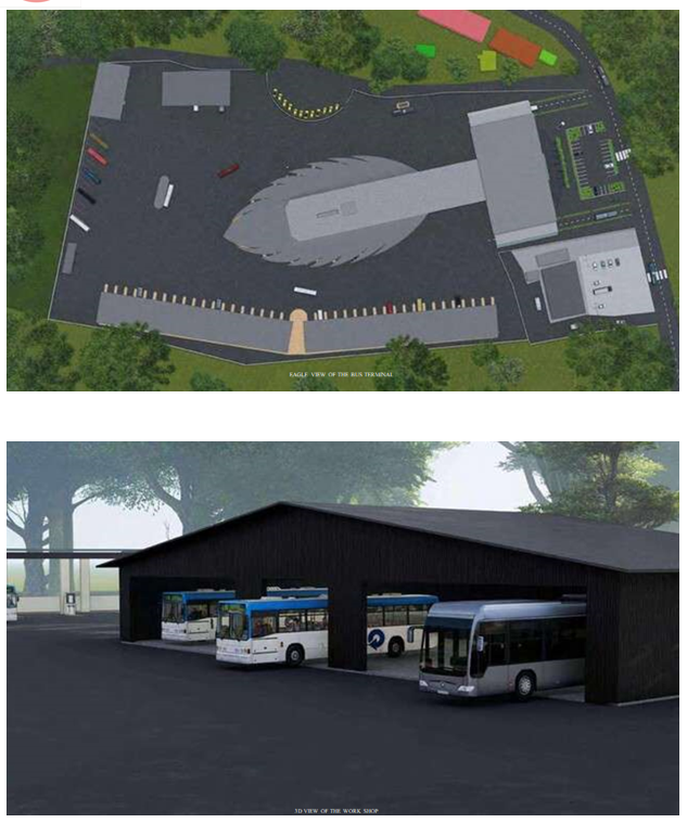
D. 2D Plan of Pattambi Bus Terminal
AutoCAD is used to draw the entire 2d plan of the bus terminal the Features and Facilities are follows:
- Shopping Complex: The inclusion of a shopping complex within the bus terminal offers convenience to passengers and visitors. It allows for a diverse range of retail options, including shops selling daily necessities, travel essentials, and local products. The shopping complex enhances the overall experience and provides economic opportunities for local businesses.
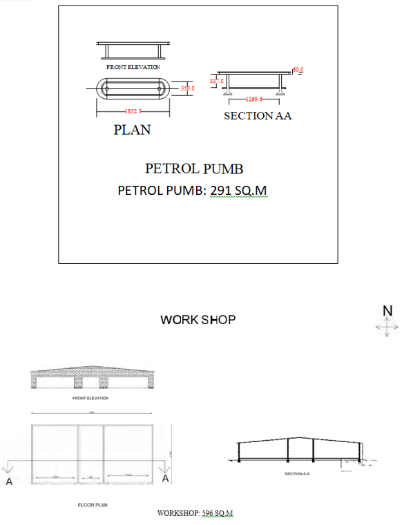
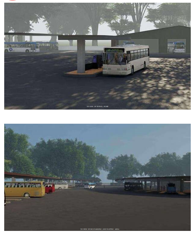
- Petrol Pump: The provision of a petrol pump within the bus terminal premises offers a convenientrefueling option for buses and other vehicles. This eliminates the need for buses to travel long distances for refueling, saving time and reducing fuel consumption. The petrol pump may also incorporate eco-friendly practices, such as providing alternative fuels or electric charging stations. The fuel station was designed with environmentally friendly features, such as fuel- efficient pumps and vapor recovery systems, to minimize air pollution.
- Hotels and Cafeteria: The presence of hotels and a cafeteria within the bus terminal area catersto the needs of passengers and visitors who may require accommodation or refreshments. These amenities contribute to a comfortable and convenient experience for travelers, particularly those with longer waiting times or layovers. A cafeteria was incorporated within the terminal, offeringa variety of food and beverage options. The cafeteria emphasized the use of eco-friendly practices, such as sourcing local and organic ingredients, minimizing food waste, and implementing recycling and composting systems.
- Toilets: Well-maintained and hygienic toilets are an essential requirement for any bus terminal. Adequate toilet facilities should be provided to accommodate a high volume of passengers. Water-efficient fixtures, proper waste management systems, and eco- friendly cleaning practices can be implemented to promote sustainability and hygiene. Environmentally friendly toiletsequipped with water-saving fixtures, such as low-flow toilets and sensor-activated faucets, were installed throughout the bus terminal. Proper waste management systems, including efficient sewage treatment and recycling, were also implemented.
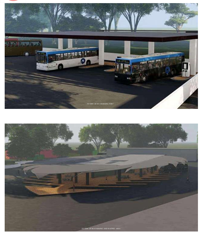
- Waiting Area: A spacious and comfortable waiting area is crucial for passengers. The design should prioritize seating arrangements, sufficient shade, natural ventilation, and aesthetic appeal. Eco-friendly materials, such as recycled furniture and sustainable flooring options, can be incorporated to align with the terminal's environmental objectives. charging stations for electronic devices, and information displays for convenience and improved passenger experience.
- Comfort Station: The inclusion of a comfort station provides additional amenities to enhance the overall experience for passengers. This may include features such as charging stations for electronic devices, Wi-Fi connectivity, information kiosks, and entertainment facilities. Energy- efficient equipment and lighting systems can be installed to minimize energy consumption.
- Medical Shop: Having a medical shop within the bus terminal area ensures immediate access to basic healthcare products and services. It provides convenience for passengers and staff, particularly during emergencies. The medical shop can stock essential medications, first aid supplies, and healthcare products.
- Workshop: A dedicated workshop within the bus terminal premises is essential for maintenance and repair of buses and other vehicles. The workshop should be equipped with necessary tools, equipment, and skilled personnel to handle routine maintenance and minor repairs. Implementing eco-friendly practices, such as proper waste disposal and recycling, can further enhance the sustainability of the workshop. The workshop was designed to meet environmental regulations and standards, ensuring proper waste management and disposal practices.
- EV Charging Spot: As the popularity of electric vehicles (EVs) increases, providing EV charging spots in the bus terminal promotes sustainable transportation. This encourages the use of electric buses and other EVs, reducing carbon emissions and air pollution. The charging spots should be strategically located and equipped with fast- charging capabilities to minimize charging time. These charging spots encouraged the use of sustainable transportation options and reduced greenhouse gas emissions.
- Air Checking Port: Including an air checking port enables passengers to conveniently check and adjust their vehicle tires' air pressure before embarking on their journeys. Properly inflated tires improve fuel efficiency and contribute to safer and more comfortable rides. The air checking port can utilize eco-friendly tire pressure gauges and air compressors. An air checking port was established within the terminal to facilitate regular maintenance and inspection of tires. Properly inflated tires help improve fuel efficiency and reduce carbon emissions.
- Feeding Room for: Recognizing the needs of mothers traveling with infants, a dedicated feeding room is essential. This private and comfortable space allows mothers to breastfeed or tend to their infants' needs in a hygienic environment. The feeding room should be equipped with seating, changing tables, and basic amenities to support the well-being of both mothers and infants.
- Prayer Hall: A prayer hall within the bus terminal accommodates the spiritual and religious needs of passengers and staff. It provides a tranquil space for prayer, reflection, and meditation. The design should consider appropriate aesthetics, proper ventilation, and universal accessibility.
- Restroom for Drivers: Along with passenger facilities, it is essential to provide dedicated restrooms for drivers. These facilities should be designed to cater specifically to their needs, including amenities such as showers, rest areas, and lockers. The restrooms should be well- maintained and easily accessible to ensure driver comfort and well-being. The restroom offered amenities such as showers, rest areas, and facilities for personal hygiene.
- Parking Area for Passengers: Adequate parking space for passengers encourages the use of public transportation by providing a secure and convenient place for private vehicles. The parking area should be well-lit, properly marked, and easily accessible. Incorporating green spaces and landscaping within the parking area enhances the overall aesthetics and reduces heat islandeffects.
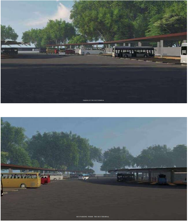
- Parking Area for Buses: A designated parking area for buses is crucial to ensure organized traffic flow and efficient operation of the bus terminal. The design should consider the number of buses, adequate space for maneuvering, and provisions for maintenance activities. The parking area can also incorporate charging infrastructure for electric buses. The parking area was designed to accommodate multiple buses and provide convenient access to the terminal facilities
- Taxi Stand: The inclusion of a taxi stand allows for seamless transportation connectivity and provides an alternative mode of transportation for passengers. It should be strategically located within the bus terminal area for easy access. Implementing eco- friendly policies for taxis, such as promoting electric or hybrid vehicles, can contribute to sustainability efforts.
- Solar Panel Implementation: Solar panels were installed on the roofs of various buildings within the bus terminal premises, such as the terminal building, shopping complex, and parking structures. The solar panels were strategically positioned to maximize sunlight exposure throughout the day. The results of implementing solar panels include:
a. Renewable Energy Generation: Solar panels generate clean and renewable energy by converting sunlight into electricity. This reduces the reliance on conventional grid electricity and minimizes greenhouse gas emissions associated with fossil fuel- basedpower generation.
b. Energy Cost Savings: The solar panels generate electricity that can be used to power various facilities within the bus terminal, such as lighting, ventilation systems, and electronic equipment. By utilizing solar energy, the bus terminal can significantly reduce its electricity costs and operational expenses.
c. Reduced Carbon Footprint: By generating electricity from solar energy, the bus terminal reduces its carbon footprint and contributes to mitigating climate change. The use of renewable energy sources helps to minimize greenhouse gas emissions, promoting acleaner and more sustainable environment.
d. Energy Independence: The installation of solar panels enhances the bus terminal's energy independence by generating its own electricity. This reduces dependence on the grid and provides a reliable source of power even during grid outages or disruptions.
E. 2D Planning using AutoCAD
AutoCAD is a commercial computer-aided design (CAD) and drafting software application. Developed and marketed by Autodesk, AutoCAD was first released in December 1982 as a desktop app running on microcomputers with internal graphics controllers. Before AutoCAD was introduced, most commercial CAD programs ran on mainframe computers or minicomputers, with each CAD operator (user) working at a separate graphics terminal. AutoCAD is also available as mobile and web apps. AutoCAD is primarily used for 2 Dimensional drawings, and even though 3D modelling is available in AutoCAD other computer-aided design software like Fusion 360, Inventor and Solidworks are preferred in 3D modelling. Since AutoCAD 2019 several verticals are included with AutoCAD subscription as Industry- Specific Toolset.
For example, AutoCAD Architecture (formerly Architectural Desktop) permits architectural designersto draw 3D objects, such as walls, doors, and windows, with more intelligent data associated with them rather than simple objects, such as lines and circles. The data can be programmed to represent specific architectural products sold in the construction industry, or extracted into a data file for pricing, materials estimation, and other values related to the objects represented Additional tools generate standard 2D drawings, such as elevations and sections, from a 3D architectural model. Similarly, Civil Design, Civil Design 3D, and Civil Design Professional support data-specific objects facilitating easy standard civil engineering calculations and representations. Softdesk Civil was developed as an AutoCAD add-on bya company in New Hampshire called Softdesk (originally DCA). Softdesk was acquired by Autodesk, and Civil became Land Development Desktop (LDD), later renamed Land Desktop. Civil 3D was later developed and Land Desktop was retired. The version used here for 2 D planning is AutoCAD 2020.AutoCAD 2020 comes with specialized toolsets and improved workflow. It includes new features such as Block Palette, etc. Refer appendix for detailed 2 d plans of the bus terminal
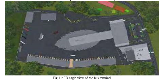
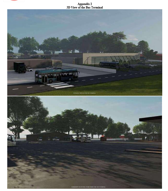
F. 3D Drawings Of The Bus Terminal
- 3D Drawing using 3d s max and lumion
Autodesk 3ds Max, formerly 3D Studio and 3D Studio Max, is a professional 3D computer graphics program for making 3D animations, models, games and images. It is developed and produced by Autodesk Media and Entertainment.It has modeling capabilities and a flexible plugin architecture and must be used on the Microsoft Windows platform. It is frequently used by video game developers, many TV commercial studios, and architectural visualization studios. It is also used for movie effects and movie pre-visualization. 3ds Max features shaders (such as ambient occlusion and subsurface scattering), dynamic simulation, particle systems, radiosity, normal map creation and rendering, global illumination, a customizable user interface, and its own scripting language.3ds Max uses polygon modeling which isa common fashion in game design. With polygonal modeling artists have a high degree of control over individual polygons which gives them a lesser range of detail and perfection in their work.After a modelis completed, 3ds Max can also be used to induce the materials and textures necessary to really bring effects to life. Adding face details similar to colors, slants, and textures will lead to advanced quality renders and game means.
There are several rendering options available in the software like scanline , arnold,V-ray. Professional CG artists will be suitable to produce photorealistic images using ways designed to mimic nature. 3ds Max is also capable of toon shading and other stylized ways popular in videotape games. 3ds Max can produce realistic simulations of fluids similar to smoke and water, both of which are used constantly in the entertainment industry. Rigid body physics in 3ds Max allows for the simulation of hard bodies similar as gemstone and wood For creating life-suchlike character models, 3ds Max provides simulations for hair, skin, clothes, and fur. And the numerous plugins available online reduce thedevelopment time for these types of models. With its own scripting language, flexible plugin architecture, and customizable user interface, 3ds Max can be substantiated to fit the requirements of any 3D work.
3ds Max really caters to architectural controversy and game asset artists the most.As for apparel and vitality, 3ds Max has everything necessary for professional work. So it’s frequently used by professional animators working on big budget flicks, indie flicks, or indeed lower marketable spots that need some 3D stir. Using Configurations, bone constraints, and kinematics, artists can amp characters using a really simple process that nearly anyone could pick up with practice. Vitality in 3ds Max revolvesaround keyframing bone parcels, making it easy to produce complex and organic stir.
Lumion is intuitive visualization software made for architects. Fast, intuitive, and reliable, Lumion software is your complete solution for architectural visualization, interior design and landscape architecture. No matter your rendering experience, Lumion makes it refreshingly easy to transform any CAD model into an experience you can feel. Shape entire landscapes and add a world of context to your designs. Make spaces feel real with fine-detailed nature, lively skies, and high-quality materials. Your Lumion render can convey atmosphere and emotion with stunning lighting, weather, and animation effects. Lumion gives you all the tools you need to bring your designs to life.It is very popular visualization software for architects. It also can change the 3D CAD designs into videos, images and online presentation. This software also helps the professionals to add environment elements like plants, animals, objects, different effect. Lumion takes much less time for rendering refer annexure for detailed3 d plans of the bus terminal.
C. Working Of Speed Breaker Generator
- General
Speed breaker power generators were installed strategically on the roadways within the bus terminal, utilizing the kinetic energy generated by vehicles passing over speed breakers. The power generators convert this kinetic energy into electrical energy. The results and benefits of implementing speed breaker power generators include:
a. Harnessing Kinetic Energy: The speed breaker power generators capture the kinetic energy of vehicles as they pass over the speed breakers. This energy is then convertedinto electricity, which can be utilized to power various applications within the bus terminal.
b. Supplemental Power Generation: The electricity generated from the speed breaker power generators serves as a supplemental power source, complementing the solar panels and grid electricity. This additional power generation reduces the overall energy demand from the grid and further enhances the bus terminal's energy efficiency.
c. Enhanced Sustainability: By harnessing the kinetic energy of vehicles, the bus terminal utilizes a renewable energy source that would otherwise go to waste. This contributes toa more sustainable energy mix and reduces the environmental impact associated with conventional power generation.
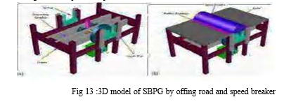
2. Speed Breaker Power Generator
It is very significant to design pollution free energy generation system. Speed breaker Power Generator (SBPG) is the most emerging technique which produces electrical power with minimum input. An experimental study to generate the electricity by SBPG is described in this paper. In this system, a rack and pinions mechanism is used for the production of electricity. When a bus reaches on the speed breaker, the rack moves downward to generate linear to rotary motion using pinions. The rotary motion is transferred to DC generator which generates DC power which is stored in batteries same as in solar technology. The generated power can be used for the domestic purpose or commercially, which are present near the speed breaker. This examined that SBPG is generating 273.24W on single push under the application of 400kg. In an hour, passing buses of 10840 kg can generate 54.59 kWh. This mechanismutilizes both downward as well as the upward motion of the rack. When the vehicle moves over the speedbreaker, speed breaker reduces its speed. As these breakers have a little height it gains an increase in its potential energy.
A vehicle weighing 1,000kg passes over the system it pushes the damper to a depth of 10 cm it can produce approximately 0.98-kilowatt power (ideally). So from one such speed breaker on a busy highway, where about 100 vehicles pass every minute, about one kilowatt of electricity can be produced every single minute. This type of energy is a non-conventional resource or renewable energy. While moving, the vehicles possess some kinetic energy and it is being wasted. This kinetic energy can be utilized to produce power by using a special arrangement called POWER HUMP. It is an Electro- Mechanical unit. It is a mechatronic type of arrangement. The amount of electricity consumed in one night by all the street lights around Chennai city (India) is equal to consumption of electricity in a remote village for one month and 14 days. The design of speed breakers was developed long ago but only utilizedby few nations, as there were limitations of speed breaker power generators. These power generators can be classified according to their mechanism and the type of power generated through it.
3. Mechanism of Working
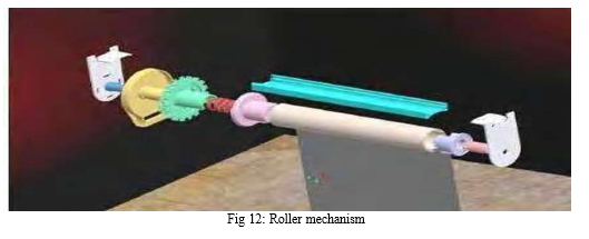
The mechanism used for the speed breaker generator is roller mechanism. A roller blind mechanism for winding and unwinding a rollable blind, the mechanism comprising a support element, a drive sprocket which is rotatably mounted on the support element for transmitting rotational movement to a blind supporting member, and a manually-movable elongate flexible drive element which includes a plurality of interlinked tooth-engaging elements, the drive sprocket including a plurality of flexible teeth engagable with the tooth-engaging elements of the flexible drive element. A roller blind mechanism as claimed in claim 1, wherein a radial extent of the teeth of the drive sprocket is equal to or greater than a maximum dimension of the tooth-engaging elements of the flexible drive element. A roller blind mechanism as claimed in claim 2, wherein the radial extent is equal to or greater than twice the maximum dimension of the tooth-engaging elements of the flexible drive element. A roller blind mechanism as claimed in claim 1, wherein the teeth of the drive sprocket flex in a circumferential direction of the sprocket.
4. Electricity Generation from roller Mechanism
Electricity is the form of energy. It is the flow of electrical Power. Electricity is a basic part ofnature and it is one of our most widely used forms of energy. We get electricity, which is a secondary energy source, from the conversion of other sources of energy, like coal, natural gas, oil, nuclear power and other natural sources, which are called primary sources. Many cities and towns were built alongside water falls that turned water wheels to perform work. Before electricity generation began slightly over 100 years ago, houses were lit with kerosene lamps, food was cooled in iceboxes, and rooms were warmed by wood-burning or coal-burning stoves. Direct current (DC) electricity had been used in arc lights for outdoor lighting. In the late-1800s, Nikola Tesla pioneered the generation, transmission, and use of alternating current (AC) electricity, which can be transmitted over much greater distances than direct current. Tesla's inventions used electricity to bring indoor lighting to our homes and to power industrial machines. How is electricity generated? Electricity generation was first developed in the 1800's using Faraday’s dynamo generator. Almost 200 years later we are still using the same basic principles to generate electricity, only on a much larger scale.
The rotor (rotating shaft) is directly connected to the prime mover and rotates as the prime mover turns. The rotor contains a magnet that, when turned, produces a moving or rotating magnetic field. The rotor is surrounded by a stationary casing called the stator, which contains the wound copper coils or windings. When the moving magnetic field passes by these windings, electricity is produced in them. By controlling the speed at which the rotor is turned, a steady flow of electricity is produced in the windings. These windings are connected to the electricity network via transmission lines. Now throwing somelight on the very new and innovative concept i.e. GENERATING ELECTRICITY FROM A SPEED BREAKER. Producing electricity from a speed breaker is a new concept that is under-going research. The number of vehicles on road is increasing rapidly and if we convert some of the kinetic energy of these vehicle into the rotational motion of roller then we can produce considerable amount of electricity, this is the main concept of this project. In this project, a roller is fitted in between a speed breaker and some kind of a grip is provided on the speed breaker so that when a vehicle passes over speed breaker it rotates the roller. This movement of roller is used to rotate the shaft of D.C. generator by the help of chain drive which is there to provide 1:5 speed ratio. As the shaft of D.C. generator rotates, it produces electricity. This electricity is stored in a battery.
Then the output of the battery is used to lighten the street lamps on the road. Now during daytime,we don’t need electricity for lightening the street lamps so we are using a control switch which is manually operated. The control switch is connected by wire to the output of the battery. The control switch has ON/OFF mechanism which allows the current to flow when needed. If a car or any heavy vehicle is coming with a speed of 100 mph on the road and passing over this roller which is fitted at the level of the road then this roller is gaining the speed nearly somewhere 90 mph (due to losses). So now suppose a cycle is coming with a speed of 20 mph and is going to pass this roller (which is moving at a speed of 90 mph) due to this difference in the speed there will be a collision that is the main reason for using this concept on the speed breaker.
VI. COST ANALYSIS
The cost analysis for the entire bus terminal project, including the shopping complex, petrol pump, hotels, cafeteria, toilets, waiting area, comfort station, medical shop, workshop, EV charging spots, air checking port, feeding room for mothers, prayer hall, restroom for drivers, parking area for passengers, parking area for buses, and taxi stand, involved a comprehensive assessment of construction, materials, labour, and other associated expenses. The exact cost estimation would require a detailed analysis and consideration of factors such as location, size, materials used, and local market conditions. The cost estimation for the construction of the bus terminal and associated facilities depends on several factors, such as the size of the terminal, materials used, and specific design requirements. The rough cost estimates based on local market conditions and material availability. Additionally, the use of eco-friendly materials, sustainable design features, plus-bitumen pavement, solar panel and speed breaker power genertor may impact the initial construction costs but can provide long- term benefits through energy savings and reduced environmental impact.
Table 7: Cost analysis
|
Table description |
No |
Quantity m2 |
Rate/Unit Rs. |
Total amount Rs. |
|
Shoppingcomplex |
1 |
2024 |
1600 |
Rs 69715200 |
|
Workshop |
1 |
576 |
150 |
Rs 1100000 |
|
Toilet |
16 |
|
60000 |
Rs 1000000 |
|
Petrol pump |
1 |
291 |
|
Rs 1000000 |
|
Electric charging port |
1 |
299 |
|
Rs 100000 |
|
Solar panel |
656 panel(120kw) |
|
|
Rs 5500000 |
|
Road pavement construction |
1 |
22789 |
131/area |
Rs 3000000 |
|
Rain water harvesting tank |
1 |
775 |
285/area |
2.21 lakhs |
|
|
|
|
Total |
Rs 82,53,6200 |
VII. RESULT AND DISCUSSION
The test result can confirm that conduct for which is suitable for the pavement of bus terminal is bitumen plus plastic. Thus, the strength of bitumen mixed with plastic is greater than the strength of bitumen without the mixes of plastic. Using plastic waste in mix will help reduction in need of bitumenby around 10% increase strength and performance of road. It is economical way to reduce the number of resources used for construction. This innovative approach helps to recycle plastic waste and enhancesthe durability and strength of the pavement. The use of plastic and bitumen also reduces the consumption of traditional aggregates and lowers the overall environmental impact of the construction. It also contributes to reducing plastic waste pollution.
The implementation of solar panels and speed breaker power generators in a bus terminal in Pattambi offers numerous benefits. Solar panels harness sunlight to generate electricity, reducing energy costs, lowering the environmental impact, and increasing energy resilience. Speed breaker power generators utilize the mechanical energy from vehicles passing over speed breakers to generate electricity, promoting sustainable energy practices and raising public awareness. Integrating these technologies creates a more sustainable and energy- efficient bus terminal, contributing to a greener and more resilient transportation infrastructure. This project serves as a model for integrating renewable energy sources into transportation hubs, promoting environmental stewardship and sustainabledevelopment.
VIII. APPENDIX 1
2D PLAN OF THE BUS TERMINAL

Conclusion
Nowadays, traffic congestion is faced by any town or cities due to urbanization. In the project work, the present situation at the existing bus station is thoroughly studied and the problems causing the traffic congestion at Pattambi junction is identified. The solutions to tackle this situation is to shift the present bus station to a new site and planning it accordingly in an efficient manner. Reconnaissance survey is conducted. Tests are conducted for the environmentally friendly materials. By incorporating solar energy, rainwater harvesting, plastic bitumen road, and speed breaker power generation, the terminal aims to minimize its ecological impact while providing a range of facilities to passengers and service providers. The test results and performance evaluation will ensure the effectiveness and efficiency of the implemented solutions, leading to a sustainable and energy-efficient bus terminal. Prepared the site plan of the proposed site. The proposed solution is a long shot, but if executed properly, step by step it will transform the image of the area near. Thus, improving the standard of living of the people in the surrounding. Using public transport itself helps reducing exhaust gas, but now there are continuous efforts to operate public transport in eco-friendly vehicles. Here are some eco- friendly operation casesof most well-known public transport means like buses.
References
[1] Abdel-Aty, R. Kitamura., P. P. Jovanis., & K. M. Vaughn. (1994). Investigation of criteria influencing route choice: initial analysis using revealed and stated preference data. Research Report UCD-ITS- RR-94-12. Institute of Transportation Studies, University of California, Davis, Calif, USA. [2] Abdel-Aty, R. Kitamura., and P. P. Jovanis. (1995). Investigating effect of travel time variability on route choice using repeated-measurement stated preference data. Transportation Research Record, no. 1493, pp. 39–45. [3] Ali Azam, M. Aqeel Aslam.,Shoukat Ali and F.Q. Yousef-Zai. (2018). Selection and/or peer- review under responsibility of Energy and Environmental Engineering Research Group (EEERG), Mehran University of Engineering and Technology, Jamshoro, Pakistan. vol. 16, pp. A205-A206, 2010. [4] M. Ashwin1, V. Mounika, Madhuri Kommineni & k. Swetha. (2020). Secure design for smart bus shelter using renewable energy, 2394-5125 vol 7, 1. [5] Kerala Municipal Building Rules,2019 [6] Census of India (2001) [7] R.Manju, Sathya S; Sheema K.(2017).Use of Plastic Waste in Bituminous Pavement, ISSN: 0974- 4290, ISSN: 2455-9555 Vol.10 No.8, pp 804-811, 2017. [8] S Logeswaran, P Indhiradevi, A Charumathy, A Anitha, Muthu Subramaniam and S Karthikeyan (2022). Review and analysis of factors influencing the design of bus station, Int. Journal of Engineering Research and Application, pp 1762 – 1771. [9] S Logeswaran, p indhiradevi, a charumathy, a anitha(2017). Design standards for planning a bus terminus, Int. Journal of Engineering Research and Application vol.3, special issue.
Copyright
Copyright © 2023 Aabitha M, A.Ashin Ashraf, Akshay K, Devika R. This is an open access article distributed under the Creative Commons Attribution License, which permits unrestricted use, distribution, and reproduction in any medium, provided the original work is properly cited.

Download Paper
Paper Id : IJRASET53928
Publish Date : 2023-06-10
ISSN : 2321-9653
Publisher Name : IJRASET
DOI Link : Click Here
 Submit Paper Online