

Ijraset Journal For Research in Applied Science and Engineering Technology
Process Parametric Optimization of CNC Vertical Milling Machine Using ANOVA Method in EN24
Authors: Mr. Barigora Fabien, Mr. P. Vijayakumar
DOI Link: https://doi.org/10.22214/ijraset.2022.43008
Certificate: View Certificate
Abstract
Materials are manufactured from casting, forging and extrusion processes have higher typical dimension tolerances due to its producing ability. So, machining processes were introduced for close tolerance assembly and improve the product working efficiencies. In response, now a day’s lots of machining processes are available such as turning, milling, drilling and grinding to overcome these problems. Milling operation is playing vital role on making the components with high accuracy and higher productivity. Subsequently, face milling operation is utilized for planning the surface of work material with improved surface texture. It is one of the important milling processes to achieve high flatness and low roughness. The work enlights the parameters influence on Surface Roughness (SR). As seen in this study, the Taguchi method provides a systematic and efficient methodology for the minimum surface roughness with far less effect that would be required for most optimization techniques. Based on the S/N ratio, the optimal parameters for the minimum surface roughness are the feed rate at level 1 (80 mm/min), the cutting speed at level 3 (1000 rpm), face mill diameter at level 3 (12 mm-E24) and the depth of cut at level 2 (2 mm). The tool diameter influences the surface roughness next to the feed rate.
Introduction
I. INTRODUCTION
A. Milling
Milling is the process of removing metal by feeding the work past a rotating multipoint cutter. In milling operation, the rate of metal removal is rapid as the cutter rotates at a high speed and has many cutting edges. Thus, the jobs are machined at a faster rate than with single point tools and the surface finish is also better due to multipoint cutting edges. The action of the milling cutter is vastly different from that of a drill or lathe tool. In milling operation, the cutting edge of the cutter is kept continuously in contact with the material being cut. The cuts pick gradually. The cycle of operation to remove the chip produced by each tooth is first a sliding action at the beginning, the cutter meets the metal and then crushing action takes place just after it is leading finally to the cutting actions. The versatility and accuracy of the milling process causes it to be widely used in modern manufacturing.
B. Face Milling
Face milling is a widely used machining operation to produce plane surfaces with defined properties. One important application of face-milled surfaces is their use as seal faces. Here, the surface quality and the edge shape of the workpiece are essential for its functionality. Non-compliance with one of the quality requirements mentioned above can lead to malfunction of a component in operation. In addition to its importance for functionality of part, an unsatisfactory edge shape complicates the manageability of the and can lead to injuries while handling the work pieces.
C. ???????Improved Productivity
It is a very complex problem in machining and depends on the machining methods as well as machining factors employed each time. The following factors have significant impact in cutting processes,
- Cutting conditions (cutting speed, feed rate, depth of cut)
- Process kinematics
- Cutting tool form and material
- Mechanical properties of processed material
- Vibrations in the machine tool system
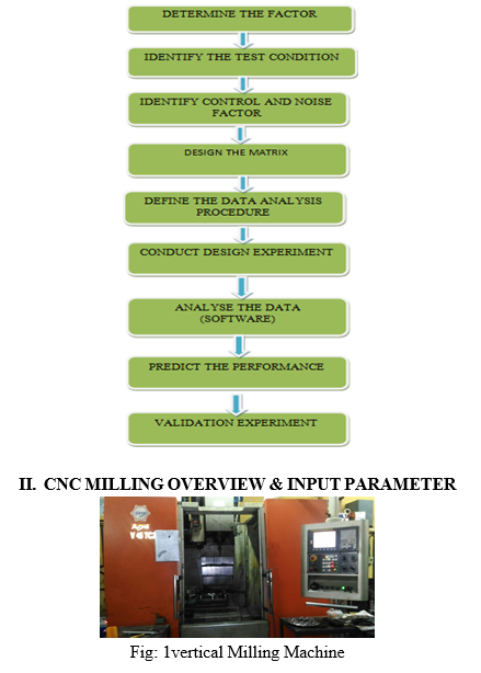
D. Experimental Plan
The proposed work approach and methodology has been elaborately shown in the flow chart.
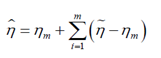
Computer Numerical Control (CNC) Milling is the most common form of CNC. CNC mills can perform the functions of drilling and often turning. CNC Mills are classified according to the number of axes that they possess. Axes are labeled as x and y for horizontal movement, and z for vertical movement, as shown in this view of a manual mill table. A standard manual light-duty mill (such as a Bridgeport™) is typically assumed to have four axes: Table x.
- Table y.
- Table z.
- Milling Head z.
The number of axes of a milling machine is a common subject of casual "shop talk" and is often interpreted in varying ways. We present here what we have seen typically presented by manufacturers. A five-axis CNC milling machine has an extra axis in the form of a horizontal pivot for the milling head, as shown below.
This allows extra flexibility for machining with the end mill at an angle with respect to the table. A six-axis CNC milling machine would have another horizontal pivot for the milling head, this time perpendicular to the fifth axis.
CNC milling machines are traditionally programmed using a set of commands known as G-codes. G-codes represent specific CNC functions in alphanumeric format.
???????A. Experimental Setup
The experiments were conducted based on L9 orthogonal array with respect to full factorial design. The three factors and each three levels with two replicates were considered based on machine tool specifications and tool manufacturer recommendations.
???????B. Machine Specifications
The experiments were conducted on BATLIBOI CHETAK-75MC-VMC fourth axis machining center
???????C. Tool and Insert
The tool diameter is a key factor while calculating the material removal rate. The diameter of tool is considered as 30 mm for this experiment. Tungsten carbide inserts are used for this experimental work.
III. MACHINING PARAMETER
A. Taguchi Approach
Basically, experimental design methods were developed original fisher. However experimental design methods are too complex and not easy to use. Furthermore, many experiments must be carried out when the number of the process parameters increases, to solve this problem, the Taguchi method uses a special design of orthogonal arrays to study the entire parameter space with a small number of experiments only. The experimental results are then transformed into a signal – to – noise (S/N) ratio to measure the quality characteristics deviating from the desired values. Usually, there are three categories of quality characteristics in the analysis of the S/N ratio, i.e., the – lower – better, the – higher – better, and the – nominal – better. The S/N ratio for each level of process parameter is compared based on the S/N analysis.
???????B. Design of Experiment
TABLE I
Process Parameters And Their Levels
|
Levels |
Process Parameters |
|||
|
Diameter mm |
Spindle Speed (N) (RPM) |
DOC mm |
Feed Rate (mm/min) |
|
|
1 |
8 |
400 |
1.5 |
80 |
|
2 |
10 |
700 |
2 |
110 |
|
3 |
12 |
1000 |
2.5 |
130 |
???????C. Experimental Data Analysis and Optimization
TABLE II
Experimental data analysis
|
Sl. No |
Diameter mm |
Speed (N) (RPM) |
DOC mm |
Feed Rate (mm/min) |
Ra (Mean) micron |
|
1 |
8 |
400 |
1.5 |
80 |
3.489 |
|
2 |
8 |
700 |
2 |
110 |
5.308 |
|
3 |
8 |
1000 |
2.5 |
130 |
7.208 |
|
4 |
10 |
400 |
2 |
130 |
6.321 |
|
5 |
10 |
700 |
2.5 |
80 |
3.487 |
|
6 |
10 |
1000 |
1.5 |
110 |
5.51 |
|
7 |
12 |
400 |
2.5 |
110 |
4.826 |
|
8 |
12 |
700 |
1.5 |
130 |
6.421 |
|
9 |
12 |
1000 |
2 |
80 |
2.299 |
???????D. S/N Ratios Values for the Experiments
TABLE III
S/N Ratios Values for the Experiments
|
Sl. No |
Diameter mm |
Speed (N) (RPM) |
DOC mm |
Feed Rate (mm/min) |
Ra (Mean) SN-Ratio |
|
1 |
8 |
400 |
1.5 |
80 |
-10.854 |
|
2 |
8 |
700 |
2 |
110 |
-14.498 |
|
3 |
8 |
1000 |
2.5 |
130 |
-17.156 |
|
4 |
10 |
400 |
2 |
130 |
-16.015 |
|
5 |
10 |
700 |
2.5 |
80 |
-10.849 |
|
6 |
10 |
1000 |
1.5 |
110 |
-14.823 |
|
7 |
12 |
400 |
2.5 |
110 |
-13.671 |
|
8 |
12 |
700 |
1.5 |
130 |
-14.790 |
|
9 |
12 |
1000 |
2 |
80 |
-8.59 |
???????E. Surface Roughness (Analysis of Variance)
TABLE VI
Response Table for Signal to Noise Ratios-Smaller is better
|
Level |
Diameter mm |
Speed (N) (RPM) |
DOC mm |
Feed Rate (mm/min) |
|
1 |
-14.170 |
-13.514 |
-13.943 |
-9.645 |
|
2 |
-13.896 |
-13.833 |
-12.582 |
-14.331 |
|
3 |
-12.352 |
-13.070 |
-13.892 |
-16.441 |
|
Delta |
1.818 |
0.763 |
1.361 |
6.797 |
|
Rank |
2 |
4 |
3 |
1 |
TABLE V
Analysis of Variance for RA, using Adjusted SS for Tests
|
Source |
Df |
Seq Ss |
Adj SS |
Adj SS |
F |
P |
% of Contribution |
|
Diameter |
2 |
5.7657 |
5.7657 |
5.7657 |
0 |
0 |
7 |
|
Speed |
2 |
0.8814 |
0.8814 |
0.8814 |
0 |
0 |
1 |
|
Doc |
2 |
3.5736 |
3.5736 |
3.5736 |
0 |
0 |
4 |
|
Feed |
2 |
72.6122 |
72.6122 |
72.6122 |
0 |
0 |
88 |
|
Residual Error |
0 |
0 |
0 |
0 |
|
|
0 |
|
Total |
8 |
82.8329 |
|
|
|
|
100F. |
???????Confirmation Test
Once the optimal level of the design parameters has been selected, the final step is to predict and verify the improvement of the quality characteristic using the optimal level of the design parameters. The estimated S/N ratio using the optimal level of the design parameters can be calculated as:
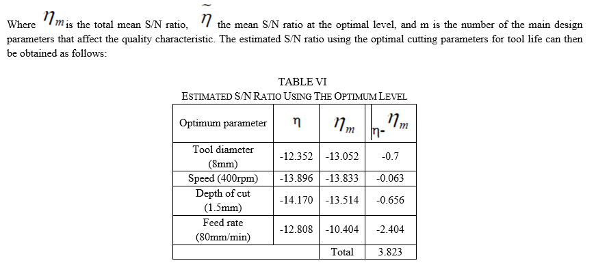
Estimated S/N ratio = -12.352+3.823 = -8.529
S/N ratio at optimum level i.e., experiment number `9' in Table 4 = -8.529
From above calculations, it is observed that estimated S/N ratio and mean S/N ratio at optimal level are almost same which indicates that our experimental and predicted results validate
Conclusion
The various parameters have to be selected for CNC milling machining. The work piece will be planned with various parameters like DOC, speed; feed angle. In order to achieve to high degree surface finish swells minimum cycle timing. As seen in this study, the Taguchi method provides a systematic and efficient methodology for the minimum surface roughness with far less effect that would be required for most optimization techniques. Based on the S/N ratio, the optimal parameters for the minimum surface roughness are the feed rate at level 1 (80 mm/min), the cutting speed at level 3 (1000 rpm), face mill diameter at level 3 (12 mm-E24) and the depth of cut at level 2 (2 mm). The tool diameter influences the surface roughness next to the feed rate. Therefore e, the tool diameter seems to be the most critical parameter and should be selected carefully in order to reduce all kinds of damages. Conceptual S/N ratio and ANOVA approaches for data analysis draw almost similar Conclusions. The confirmation experiments were conducted to verify the predicted optimal parameters with the experimental results. The comparison of the predicted and experimental values of Surface roughness using the optimal cutting parameters, showed a good agreement between the predicted and experimental results of order of 98.61%.
References
[1] Fisher, Ronald Studies in Crop Variation. I, “An examination of the yield of dressed grain from Broadbalk”, Journal of Agricultural Science, (1918), 11:107135. doi:10.1017/S0021859600003750. [2] Julie Z. Zhang, Joseph C. Chen, E. Daniel Kirby, “Surface roughness optimization in a face-milling operation using the Taguchi design Method”, Journal of Materials Processing Technology, (2006), 233-238 [3] Dae Kyun Baek, Tae Jo Ko, Hee Sool Kim, “Optimization of feed rate in face milling operation using a surface roughness model”, International Journal of machine Tools & Manufacturer, (2010), 452-458 [4] Vijayan N. Nair, Bovas Abraham, Jock MacKay, John A. Nelder, George Box, Madhav S. Phadke, Raghu N. Kacker, Jerome Sacks, William J. Welch, Thomas J. Lorenzen, Anne C. Shoemaker, Kwok L. Tsui, James M. Lucas, Shin Taguchi, Raymond H. Myers, G. Geoffrey Vining, C. F. Jeff Wu, “Taguchi’s Parameter Design; A Panel Discussion”, Techno metric, (1992), 133-146 [5] Sakuma, K., Seto. M, Tool wear in cutting glass-fiber-reinforced plastics, The relation between fiber orientation and tool wear, JSM E vol.26, pp. 1420-1427, 1983, [6] Tagliaferri V, Caprino G, Diterlizzi A., Effect of drilling parameters on the finish and mechanical properties of G FR P composites. International Journal Machine Tools Manufacturing, vol. 30, pp. 77-84,1990. [7] Bhatnagar, N., Ramakrishnan, N., Naik, N.K., Komanduri, R., On the machining of fiber reinforced plastic (FR P) composite laminates. International Journal Machine Tools Manufacturing. V of 35, pp, 701-716,1995. [8] Piquet R, Ferret B, Lachaud F, Swider P., Experimental analysis of drilling damage in thin carbon/epoxy plate using special drills. Composites, Part A Vol -31, pp. 1107-1115,2000. [9] Enemuoh, Ugo E., El-Gizawy Sherif A., Chukwujekwu Okafor A., An approach for development of damage-free drilling of carbon fiber reinforced thermosets. International Journal of Machine Tools and Manufacture; V ol-41(12), pp 795-814,2001. [10] Lee E-S., Precision machining of glass fiber reinforced plastics with respect to tool characteristics. International Journal Advance Manufacturing Technology. Vol-17, pp.791-798, 2001.
Copyright
Copyright © 2022 Mr. Barigora Fabien, Mr. P. Vijayakumar. This is an open access article distributed under the Creative Commons Attribution License, which permits unrestricted use, distribution, and reproduction in any medium, provided the original work is properly cited.

Download Paper
Paper Id : IJRASET43008
Publish Date : 2022-05-20
ISSN : 2321-9653
Publisher Name : IJRASET
DOI Link : Click Here
 Submit Paper Online