

Ijraset Journal For Research in Applied Science and Engineering Technology
Comparative Analysis of RCC Structure with Energy Dissipation Device and Composite Structure
Authors: Arunendra Kumar Mishra, Dr. Raghvendra Singh
DOI Link: https://doi.org/10.22214/ijraset.2022.48203
Certificate: View Certificate
Abstract
The ground movement which occurred naturally and creates disaster to cause damage of the structures is called Earthquake. In the earth’s crust seismic activities occur that creates waves. These waves transmit to structures through foundation. Thus, due to this earthquake movements, inertia force is invoked in structure resulting in damaging the whole or part of structure. Base isolation is the recent development for seismic resistant designs, this may not be totally controlling the ground movement but helps in minimising the impact of ground movement. Base isolation enables in reduction of earthquake forces by lengthening the period of vibration of structure. Also, the structural response accelerations are less than the ground acceleration because of Base isolation. It helps in limiting the effects and after effects of earthquake and that’s why it is widely accepted in the whole world as one of the most effective approaches in past few years. The response spectrum analysis is conducted on three different model using CSI ETABSv19, several values of all three models were found out from Structure. Structure is Located in Earthquake Zone IV. Three models are used for analysing the response of the building. The results of frequency, time period, displacement, drift, storey overturning moment and storey stiffness are compared for G+25 RC frame structure with shear wall, RC frame structure with base isolation and composite structures.
Introduction
I. INTRODUCTION
This study examines the comparative analysis of the following three model i.e., RC frame structure with shear wall, RC frame structure with base isolation and composite structure. The main purpose of Shear walls to provide large strength and stiffness to building, which significantly reduces lateral sway of the building and thereby reduces damage to structure and its contents. In present work linear dynamic analysis of G+25 RC frame structure with shear wall, RC frame structure with base isolation and composite structures are analysed and compared. effect of all these structural components is calculated on structure having 25 Storey.
II. NEED OF BASE ISOLATION
- Provides good flexibility to the structure.
- Make building earthquake resistant.
- Story become more serviceable.
- Earthquake prone zones of developed countries are now making compulsory to have a isolated base in the building with higher importance.
- Reduces steel reinforcement.
- Reduces the base shear, and overturning moment of the structure.
- Increases time period of the structure.
As compared to fixed base structure, Base isolated structure provides more ductility to the structure and now days use of base isolation structure is very common in earthquake prone areas.
III. NEED OF COMPOSITE STRUCTURE
- High flexibility in design and ease of manufacturing.
- Ideal material in earthquake prone locations due to its high strength, stiffness and ductility.
- The size of the elements can be reduced, thus increasing the strength-to-weight ratio.
- Facilitate faster project construction.
- Meet the demand for long span construction, a modern trend in architectural design.
- Allows easy structural repair and modification.
- Precisely designed concrete and steel composite members prevent brittle fracture of reinforced concrete members and have high ductility.
- Encased steel frame can be used as a shoring system during construction process.
As compare to conventional RCC structure, composite structure is widely used in practice now-a-days because of better seismic performance. Hence these structures are demand in many countries which are seismic prone area irrespective of developed or under developed.
IV. OBJECTIVE
The objective is to perform the Linear dynamic analysis of G+25 RC frame structure with shear wall, RC frame structure with base isolation and composite structures and compare their results. effect of all these structural components is calculated on structure having 25 Storey which is Located in Earthquake Zone IV.
Analysis is done with the help of ETABSv19 software.
- To compare the result for RCC and composite structure of G+25 storey.
- To understand the behaviour of RCC and composite structure in Response Spectrum analysis.
- To determine the effect of base isolation in time period, base shear, overturning moment, base shear, storey drift in high rise structure.
- To determine the behaviour of composite structure in response spectrum analysis.
- To determine the behaviour of structure base isolation and its comparison with composite structure and with RC frame structure with shear wall.
V. LINEAR DYNAMIC ANALYSIS
Linear dynamic analysis or Response spectrum Static procedures are appropriate when the effects of the higher mode are negligible. Thisis often true for short-term, conventional buildings. Therefore, for high-rise buildings, buildings with irregular or non-orthogonal torsion systems, a dynamic process is required.In the linear dynamics process, the building is modelled as a Multi Degree of Freedom (MDOF) with a linear elastic stiffness matrix and an equivalent viscous damping matrix. The seismic input was modelled using either modal spectrum analysis or time series analysis, but in both cases the respective internal forces and displacements were determinedby linear elastic analysis. The advantage of these linear dynamic procedures over linear static procedures is that higher modes can be considered. However, they are based on a linear elastic response and, therefore, applicability decreases with increasing nonlinear behaviour, which is approximated by the overall force reduction coefficients. In linear dynamics analysis, the response of the structure to ground motion is calculated in the timedomain, so all phase information is retained. Only linear properties are assumed. The analytical method can use the decomposition method as a means to reduce the degrees of freedom in the analysis.
VI. MODELLING AND ANALYSIS
The linear Dynamic Analysis is conducted on three different model using CSI ETABS19, severalvalues of model were found out from RC with shear wall, RC frame with base isolation and Composite Structure. IS:1893-2016 guidelines are used for the Dynamic Analysis of G+25 story RC frame structure with shear wall, RC frame structure with base isolation and composite structure is done.
Different types of models used for analysis
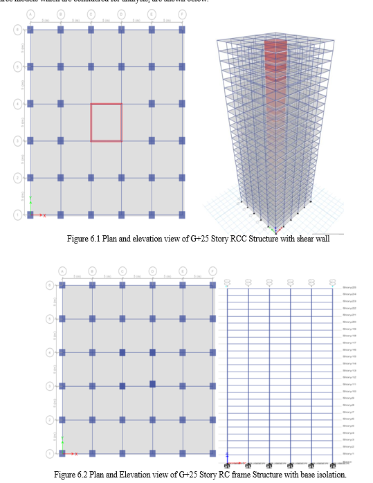
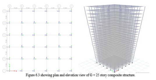
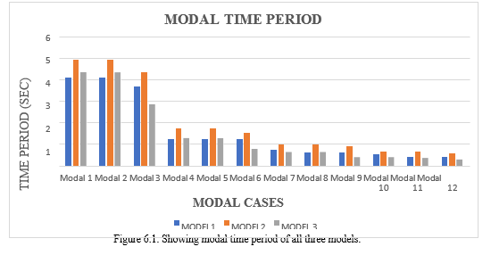
Model 1: G+25 RC frame structure with shear wall. Model 2: G + 25 RC frame structure with base isolation. Model 3: G+ 25 Composite Structure.
|
Table 6.1 data used for analysis of RC frame structure |
||
|
SN. |
Particulars |
Dimension / Value |
|
1 |
Plan dimension |
25 x 25 m |
|
2 |
Height of the bottom storey |
3.6 m |
|
3 |
Total Height of building |
75.6 m |
|
4 |
Height of parapet |
1.2m |
|
5 |
Thickness of slab |
200mm |
|
|
Seismic zone |
IV |
|
|
Importance factor |
1.2 |
|
6 |
Zone factor |
.24 |
|
|
Damping factor |
5% |
|
|
Floor finish Live load at all floor Wall load Parapet wall Density of concrete Density of steel Density of brick |
2.0 KN/m2 |
|
|
2.0 KN/m2 |
|
|
|
12 KN/m |
|
|
7 |
5.96 KN/m2 25 KN/m2 |
|
|
|
7850 KG/m2 |
|
|
|
20 KN/m3 |
|
|
8 |
Grade of Concrete Grade of reinforcing steel Soil condition |
M30 HYSD500 Medium |
|
9 |
Grade of beam and column Size of beam Size of column |
M30 300 x 500 mm 1000 x1000 mm |
|
Table 6.2 data used for analysis of composite structure
|
||
|
S. No. |
Particulars |
Dimension/value |
|
1 |
Plan Dimension |
25x25 m |
|
2 |
Total height of the building |
75.6 m |
|
3 |
Height of bottom storey |
3.6 m |
|
4 |
Height of each storey |
3 m |
|
5 |
Height of parapet |
1.2 m |
|
6 |
Thickness of slab Thickness of profiled deck Thickness of walls |
200 mm 75-100 mm 230 mm |
|
7 |
Seismic zone Importance factor Zone factor Damping ratio |
IV 1.2 0.24 5% |
|
8 |
Floor finish Live load at all floors Wall load Parapet wall Density of concrete Density of steel Density of brick |
2.0 KN/m2 2.0 KN/m2 12 KN/m 5.96 KN/m 25 KN/m2 7850 KG/m3 20 KN/m3 |
|
9 |
Grade of concrete in column Grade of deck Grade of reinforcing steelSoil condition |
M30 M20 HYSD500 Medium soil |
A. Design Data For LRB
|
Table 6.3 data used for LRB design |
|||
|
1 |
Seismic zone factor, Z |
0.3 |
(UBC 97, Vol-2, Table 16-I & Zone Map) |
|
2 |
Seismic Source Type |
B |
|
|
3 |
Near source factor, ???????? |
1 |
(UBC 97, Vol-2, Table 16-S) |
|
4 |
Near source factor, ???????? |
1 |
(UBC 97, Vol-2, Table16T) |
|
5 |
Z???????? |
0.3 |
|
|
6 |
Maximum capable earthquake response coefficient, ???????? |
1.5 |
(UBC 97, Vol-2, Table A-16- D) |
|
7 |
Soil Profile Type |
SD |
(UBC 97, Vol-2, Table 16-J) |
|
8 |
Seismic coefficient, ???????? = ???????????? |
0.54 |
(UBC 97, Vol-2, Table 16-R) |
|
9 |
Seismic coefficient, ???????? |
0.36 |
(UBC 97, Vol-2, Table 16-Q) |
|
10 |
Choose Response Reduction Factor, R for SMRF |
8.5 |
(UBC 97, Vol-2, Table 16-N) |
|
11 |
For SMRF/IMRF/OMRF Structural System Above the Isolation Interface, RI |
2 |
(UBC 97, Vol-2, Table A-16-E) |
|
12 |
Effective Damping (βd or βm ) |
0.15 |
15% Damping [] |
|
13 |
Damping coefficient, ???????? or ???????? |
1 |
Interpolate (UBC 97, Vol-2, Table A-16-C) |
B. Maximum Load Obtained after dynamic analysis on column is being taken for design of LRB
|
Table 6.4 Design Data for LRB OF G +25 for lateral load of 20500 KN |
||
|
Rotational Inertia |
0.731550068 |
KN/m |
|
For U1 Effective Stiffness |
20624555.58 |
KN/m |
|
For U2 & U3 Effective Stiffness |
20624.5556 |
kN-m |
|
For U2 & U3 Effective Damping |
0.15 |
|
|
For U2 & U3 Distance from End-J |
0.00490 |
m |
|
For U2 & U3 Stiffness |
157650.0916 |
KN/m |
|
For U2 & U3 Yield Strength |
772.8317928 |
KN |
C. Descriptions Of Models
All three models which are considered for analysis, are shown below.
VII. RESULTS AND DISCUSSION
A. Free Vibration Analysis
Modal analysis is the study of the dynamic properties of system in the frequency domain. It is the field of measuring or calculating and analysis the dynamic response of the structure during exciting. In structural engineering modal analysis used the overall mass and stiffness of a structure to find the various periods at which it will be naturally resonant. These periods of vibration are essential in earthquake engineering. Modal analysis is the process of determining the inherent dynamic properties of a system in the form of natural frequencies, damping coefficients, and modal shapes, and using them to build a mathematical model of the behaviour. The mathematical model that is formulatedis called the modal of the system, and the information about the properties is called modal data. The free vibration analysis of G+ 25 storey RC frame structure with shear wall, RC frame structure with base isolation and composite structure are performed to get a dynamic structural behaviour.
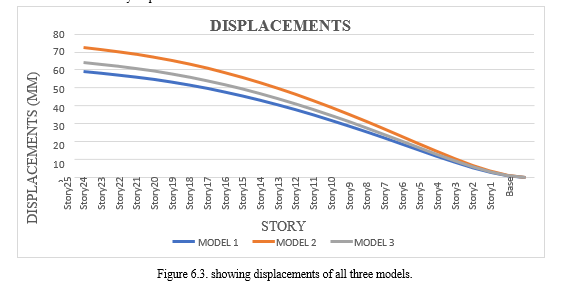
The modal time period is maximum in model 2 which is 4.93 seconds and minimum in model 1 i.e., G +25 RC frame structure with shear wall at core is 4.08 seconds and Modal time period in model 3 is 4.356 seconds.
B. Response Spectrum Analysis (IS:1893-2016)
The Response Spectrum analysis is carried out as per Indian Standard and Story Displacement, Story Shear, Story Overturning Moment, Story Stiffness are discussed for all G+25 story model.
C. Storey Displacement
Story displacement is the lateral displacement of the story relative to the base. Response spectrum analysis of G+25 story RC frame structure with shear wall, RC frame structure with base isolation and composite structure are performed. Story displacement is the lateral displacement of the story relative to the base. story displacement is maximum in model 2 which is 72.481 mm and minimum in model 1 which is 58.956 mm. story displacement in model 3 is 64.12 mm.
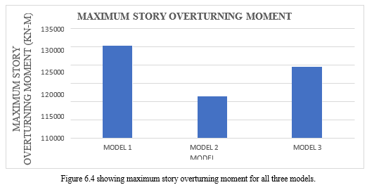
D. Maximum Story Overturning Moment
The overturning moments are obtained by multiplying the story shear by the distance to the centre of mass above the elevation considered. story overturning moment is maximum in model 1 which is 130235.69 KN-M and minimum in model 2 which is 116373.34 KN-M. story overturning moment in model 3 is 124470.64 KN-M.
E. Story Drift
Storey drift is the difference of displacements between two consecutive story divided by the height of that story and Story displacement is the absolute value of displacement of the storey under action of the lateral forces.
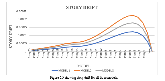
Story drift is maximum in model 2 and minimum in model 1. After analysis and all design check as per IS: 1893 (2016), storey drift satisfies the design criteria and storey drift value is not exceeding 0.004 times storey height.
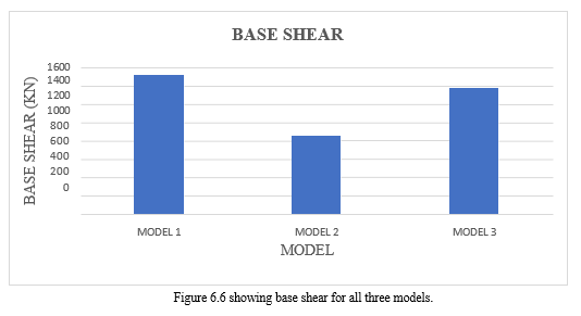
F. Base Shear
Base shear is the estimation of maximum expected lateral force which will occur at the base of a structure due ground motion during the earthquake. Due to seismic activities, the ground start moving. Due to the movement of ground, lateral force is developed in opposite direction of motion. That developed lateral force due seismic motion at the base of the structure is called base shear. base shear is maximum in model 1 which is 1514.36 KN and minimum in model 2 which is 853.66 KN. base shear in model 3 is 1366.87 KN.
VIII. FUTURE SCOPE
G+25 storey RC frame structure with shear wall, RC frame structure with base isolation and composite structure.
- Performance based seismic analysis can be done and its performance criteria can be checked from FEMA 356.
- Extension of this study on other RCC framed buildings. Performance of base isolation oversteel structure.
- Similar analysis with varying the height of the structure.
- Performance of similar structure can be checked with High Damping Rubber Bearing.
- Cost comparison of 30,35 and 40 story structure can be done using LRB and other lateral load resisting system i.e., shear wall, bracings, etc.
- Nonlinear dynamic analysis of RC frame structure with shear wall and the same structure with optimized section can be done.
Conclusion
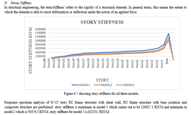
A. Time Period 1) The modal time period is maximum in model 2 which is 4.93 seconds and minimum in model 1 i.e., G +25 RC frame structure with shear wall at core is 4.08 seconds and Modal time period in model 3 is 4.356 seconds. 2) Modal time period in model 2 is 20.83 % more than that of model 1 and 13.17% more than that of model 3. 3) Because of base isolation in model 2 the ductility of structure increases significantly which leads to increase in time period and decrease in frequency. B. Story Displacement 1) Story displacement is maximum in model 2 which is 72.481 mm and minimum in model 1 which is 58.956 mm. story displacement in model 3 is 64.12 mm. 2) Story displacement in model 2 is 22.94% more than model 1 and 13.04 % as compare to model 3 respectively. 3) As rigidity increases displacement decreases and vice-versa. C. Maximum Story Overturning Moment 1) Story overturning moment is maximum in model 1 which is 130235.69 KN and minimum in model 2 which is 116373.34 KN. story overturning moment in model 3 124470.64 KN. 2) Maximum story overturning moment in model 1 is 11.91 % more than that of model 2 and 4.63% more than that of model 3. D. Story Drift 1) Story drift is maximum in model 2 and minimum in model 1. After analysis and all design check as per IS: 1893 (2016), story drift satisfies the design criteria and story drift value is not exceeding 0.004 times story height. 2) As the stiffness of the structure increases the drift ratio decreases and vice-versa. E. Base Shear 1) Base shear is maximum in model 1 which is 1514.36 KN and minimum in model 2 which is 853.66 KN. base shear in model 3 is 1366.87 KN. 2) Base shear in model 2 is reduced by 43.62 % as compare to model 1 and 37.54 % as compare to model 3 respectively. 3) As mass of a structure increases base shear also increases. F. Story Stiffness 1) Story stiffness is maximum in model 1 which comes out to be 120627.1 KN/M and minimum in model 2 which is 91676.5 KN/M. story stiffness for model 3 is 102533.5KN/M. 2) Story stiffness in model 2 is 31.57 % less than model 1 and 11.84 % less than as compare to model 3. 3) As the ductility of the structure increases, stiffness of the structure decreases and vice- versa.
References
[1] Barbat A.H. and Bozzo L.M. (1997) “seismic analysis of base-isolation for building systems.” worldwide magazine technology, Engineering and era research (IJSETR), four (four), 971- 974. [2] Bozzo T.X. and Ming L.U. (2008). “Experimental and analytical evaluation of a base isolation system with rubber bearing”, ICCTT. [3] Panchal D.R. and Marathe P.M. (2011). “Advanced Design of Composite Steel-Concrete Structural Element.” Journal Of Engineering Research and Applications 4 (7): 124– 38 [4] Renavikar A V, Suryawanshi Y. July, (2013). “Comparative Study on Analysis and Cost of RCC and Steel Composite Structure”. ISSN: 2319-7064, Volume 5, Issue 7, IJSR. [5] Shashikala K and S.V.Itti. (2013). “Comparative Study of RCC and Composite Multi- storeyed Buildings”. ISSN: 2277-3754, Volume 3, Issue 5, IJEIT. [6] Harne V.R. (2014) “Comparative Study of Strength of RC Shear Wall at Different Location on Multi-storied Residential Building” International Journal of Civil Engineering Research. ISSN 2278-3652 Volume 5, Number 4 (2014), pp. 391-400. [7] Ahamad SA, Pratap K.V. (2020) “Nonlinear Seismic Analysis of Existing RC School Buildings: The “P3” School Typology Department of Civil Engineering, ISE. [8] Mujawar Z, Sangave P, January, 2015. “Comparative Evaluation of Reinforced Concrete,Steel And Composite Structure Under the Effect of Static and Dynamic Loading”. ISSN: 2248-9622, Volume 5, Issue 1, IJERA, Pg. No:41-44. [9] Sangave P, S Waghmare, R Shete, V Mankondi, V Gundla.February, 2015. “Comparative Study of Analysis and Design of RC and Steel Structure”. ISSN: 2229-5518, Volume 6, Issue 2, IJSER [10] Sattainathan.A, Nagarajan.N. March, 2015 “Comparative Study on The Behavior of Rcc Steel and Composite Structure (B+G+20 Storeys)”. Issn: 2395-3837, Volume 1, Issue 3, Ijacee, Pg. No:21-26. [11] Cholekar S.B., Basavalingappa S. M, July-2015. “Comparative Analysis of Multistoried RCC and Composite Building Due to Mass Irregularity”, ISSN: 2395-0072, Volume 2, Issue 4, IRJET. [12] Patil V, Kewate S, August-2015 “Comparative Study on Dynamic Analysis of Composite RCC and Steel Structure”. ISSN: 2349-4476, Volume 3, Issue 8, IJETMAS. [13] Zaveri, Bhavin H., Bhargav K. Panchotiya, Smit U. Patel, And Pratik A. Bilimoria. 2016. “Parametric Study of RCC, Steel and Composite Structures Under Seismic Loading.” International Journal of Civil Engineering and Technology 7 (4): 127–47. [14] Desai S. and John K. (2015). “Seismic performance of base isolated multi-storey building. “Worldwide journal of scientific & Engineering studies, 6 (12), 84-89 [15] Khan M.A.2017 Comparative Study Of R.C.C & Structural Steel -Concrete Composite Frame for Linear and Non-Linear Analysis [16] Vinit G, Kadia N, Samanta K, October-2018. “Comparative Study of Rcc and Steel Structure for Different Floor Heights”. ISSN: 2349-2163, Volume 5, Issue 10, Ijirae. [17] Jyothi D N, February-2018 “Comparative Analysis of Rcc and Steel Structure”. Issn: 23950072, Volume 5, Issue 2, IRJET. [18] Paulo A. G. Piloto, Lucas M.S. Prates, Carlos Balsa, Ronaldo Rigobello ‘Fire Resistance of Composite Slabs with Steel Deck: Experimental Analysis and Numerical Simulation. [19] Wagh P.H, Kulkarni S. K., Kadlag V, 2019. “Comparative Study on Analysis and Design of RCC and Composite Structure”, ISSN: 2454-132X, VOLUME 5, ISSUE 3, IJARIIT. [20] Jagadale S, Shiyekar M.R. and Ghugal Y.M. July-2019 “Comparative Study of Steel, RCC and Composite Frame Building”. ISSN: 2395-0072, Volume 6, Issue 7, IRJET. [21] Rana M 2019 “comparative study in steel structure on better resistance against lateral load” ISSN: 2764-1322X, Volume 5, Issue 5, IJARIIT [22] Patel K, Thakkar S. 2019 “Analysis of CFT (Concrete Filled Steel Tube), Rcc and Steel Building Subjected to Lateral Loading”, Elsevier. [23] Savadi S. and Hosur V.2019 “Comparative Study of RCC, Steel and Composite Structures for Industrial Building”. ISSN: 2395- 4396, VOLUME 5, issue 4, IJARIIE. [24] Bhanu P.M. (2021) “Comparative Study of Composite RCC and Steel Structure” International Journal of Advanced Engineering Research and Studies III (I): 88–93. [25] Nassani D.E. and Mustafa W.A. (2021). “Seismic Base isolation in reinforced Concrete structures.” international magazine of studies studies in technology, Engineering and era, 2(2), 1-thirteen. [26] IS: 456-2000 (Indian Standard Plain Reinforced Concrete Code of Practice)– Fourth Revision. [27] IS: 1893-2002 (part-1), Criteria for earthquake resistant design of structures, fifth revision, Bureau of Indian Standards, New Delhi, India. [28] Bureau of Indian Standards: IS:875-1987, (part 1), Dead Loads on Buildings and Structures, New Delhi, India. [29] IS: 875-1987 (part-2) for Live Loads or Imposed Loads, code practice of Design loads (other than earthquake) for buildings and structures. [30] Duggal SK. Earthquake Resistant Design Structures. Oxford university press YMCA library building, New Delhi, 2010. [31] IBC (2000). “International constructing Code”, worldwide Code Council, Inc., Virginia, U.S.A. [32] IS: 13920 (2016). “Ductile layout and detailing of reinforced concrete systems subjected to seismic forces-code of practice.” Bureau of Indian requirements, New Delhi, India. [33] IS: 1893 (element I, 2002). “Standards for earthquake resistant layout of systems, element 1: general provisions and buildings [CED 39: Earthquake Engineering]”, Bureau of Indian standards, New Delhi, India. [34] IS: 1893 (part I, 2016). “Standards for earthquake resistant design of systems, component 1: trendy provisions and homes [CED 39: Earthquake Engineering]”, Bureau of Indian standards, New Delhi, India.
Copyright
Copyright © 2022 Arunendra Kumar Mishra, Dr. Raghvendra Singh. This is an open access article distributed under the Creative Commons Attribution License, which permits unrestricted use, distribution, and reproduction in any medium, provided the original work is properly cited.

Download Paper
Paper Id : IJRASET48203
Publish Date : 2022-12-17
ISSN : 2321-9653
Publisher Name : IJRASET
DOI Link : Click Here
 Submit Paper Online