

Ijraset Journal For Research in Applied Science and Engineering Technology
Real Time Monitoring of Axis Movement of Lathe Machine Tool
Authors: Prof. R. R. Chavan , Prof. H. K. Shete , Sayyad M. Ibrahim N, Bagwan M. Saad, Mujawar M. Kaif A., Jadhav Somnath S., Mane Pavan A.
DOI Link: https://doi.org/10.22214/ijraset.2023.51779
Certificate: View Certificate
Abstract
The lathe machine has two axis i.e longitudinal and transverse which are manually controlled by rotation of handwheel. This leads to error causing dimensional variation This research paper presents a real-time monitoring system for a transverse axis movement of lathe machine tool that uses a 400-pulse rotary encoder to measure the rotation of the lead screw in degrees from 0° to 360°. An Uno Arduino is utilized to set the program of the encoder shaft\'s rotation and the program of 360° rotation of the encoder, which is connected to the lead screw of the lathe machine through a muff coupling. When the lead screw rotates 360°, the tool moves forward by 10.20mm for a cut. Three displays are used to display the rotation of the encoder, the count of rotation, and the cut of tool. An SMPS power supply is employed to provide electrical power.
Introduction
I. INTRODUCTION
In the manufacturing industry, lathe machines are used for cutting, drilling, and shaping metal or wood. The lathe machine's lead screw rotation determines the cutting speed and depth of the tool. Therefore, real-time monitoring of the lead screw's rotation is development of ensure precise and efficient cutting. This paper presents a monitoring system that utilizes a rotary encoder to measure the lead screw's rotation and an Arduino board to set and control the encoder's rotation program. The encoder shaft is connected to the lead screw through a muff coupling, and when the lead screw rotates 360°, the tool moves forward by 10.20mm for a cut.
The rotation count of the encoder, the cut of the tool, and the set program are displayed on three separate displays for real-time monitoring. An SMPS power supply is utilized to provide electrical power for the system,
A. Comparison of Manual Operation with Measuring Method
The manual operation of a lathe machine involves the operator manually adjusting the cutting tool's position and depth, which can result in human error and imprecise cuts. In contrast, the measurement method presented in this paper utilizes a rotary encoder and an Arduino board to precisely control the tool's on monitoring system provides accurate and efficient cutting, resulting in a higher-quality finished product.
Additionally, the manual operation of a lathe machine requires significant operator skill and training, whereas the measurement method presented in this paper is more user-friendly and accessible.
The use of displays to monitor the system's performance allows for easy and quick adjustments as needed, making it an attractive option for manufacturers seeking to increase efficiency and reduce errors.
Overall, the measurement method presented in this paper offers significant advantages over manual operations in terms of precision, efficiency, and ease of use. It also reduces the risk of operator error and increases the consistency of the cutting process. Additionally, the real-time monitoring system of driver Axis tool allows for immediate adjustments to be made, resulting in improved productivity
- Components: The components required are lathe machine of normal specification, Shaft hole, Encoder, UNO Arduino Controller, Wires, SMPS, LED 4 Digit visual display. These components are explained in the following,
- Muff Coupling: Sleeve coupling is the simplest example of a rigid style coupling. It consists of a cast-iron sleeve (hollow cylinder) or muff. It has an internal diameter equal to the external diameter of the shafts being connected. A gib head key is used to restrict the relative motion and prevent slippage between the shafts and the sleeves. To hold the handwheel rotating shaft with the shaft holder and encoder , muff coupling is used which is designed as per requirement of the outer diameter of shaft and the outer diameter of encoder shaft . The design of coupling is done in such a way that there is no load occurring on the encoder shaft and encoder shaft easily rotate with the handwheel shaft.
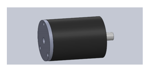
- Incremental Rotary Encoder: Incremental rotary encoders translate rotational movement into electrical signals for more precise control of automated systems. Unlike absolute encoders that measure angle, incremental encoders produce alternating high and low pulses as rotation occurs, which may indicate speed and direction of the rotating object. The main difference between Absolute and Incremental Rotary Encoder An ABSOLUTE movement moves to a coordinate based on your zero point. An INCREMENTAL movement moves a distance based on your current position. An incremental movement does not take your part zero point into consideration. To measure the rotation of rotating shaft is done by the use of dc 5-24v 400 pulse Incremental photoelectric rotary encoder. Which measures the rotation of rotating shaft in 0-360 degree. Which counts the rotation given by the shaft and process to the microcontroller.
- Type: Incremental rotary encoder dc 5-24v 400 p
- Reason to use : Measures rotary movement ,does not save previous memory and low cost
4. Arduino Micro-Controller: Arduino UNO is a low-cost,flexible, and easy-to-use programmable open-source microcontroller board that can be integrated into a variety of electronic projects. This board can be interfaced with other Arduino boards, Arduino shields, Raspberry Pi boards and can control relays, LEDs, servos, and motors as an output.
Type: Arduino UNO micro-controller
Reason to use : Easy to use programmable and cost is low
5. SMPS:(Switch mode power supply) A 5V output is most commonly used when the end application needs powering via a USB connector, for example a mini/micro B or Type-C plug. Or, if space is at a premium, the DC cable and USB plug can be removed altogether and replaced with a female socket on the case like on phone chargers. The use of SMPS is to supply the required amount voltage and ampere to the encoder.
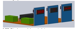
6. LED Display: Visual displays are depictions that convey information by means of elements beyond pure text. Examples include diagrams, maps, and computer interfaces. To display the readings carried out by encoder and microcontroller visual display is used. which is useful to the machine operator to observe the readings. LED Display will be used. The reading which carried out by the microcontroller is in 4-digit so the 4-digit LED Display is used as shown.
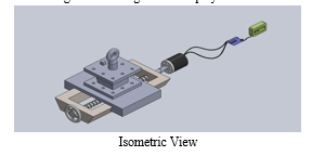
7. Construction & Working: In this first start from shaft holder which will manufactured according to requirement of the size of wheel shaft of the machine. The engagement of the shaft holder and Encoder is done by coupler which is manufacture according to the size of requirement, To display the outcome Encoder is used to measure the rotation of shaft in degree. Electronic board is placed to process electronic instrument. Micro Controller is used to set the program of the actual reading carried out by the Encoder .and this idea came to us from research paper which mentioned in Reference to the first line below Coupling(1). Encoder(2) (3),(4). Uno Arduino(5),(6),(7). Display (8),(9),(10). SPMS(11),(12) . Actual reading carried out by the above electronic instrument is displayed on screen.

II. DIMENSION CALCULATIONS
A. Shaft Holder
Actual length of shaft holder = 30 mm
Outer diameter of shaft holder
(Do) = 28 mm
Inner diameter of shaft holder to shaft = 17 mm
Inner diameter of shaft holder to coupler = 14 mm
Actual length coupler = 40 mm Diameter of coupler
to shaft holder = 15 mm
Diameter of coupler to the
shaft of Encoder = 13 mm
Inner diameter of coupler
to hold Encoder shaft = 06 mm
B. Encoder
C. Connection
- Green = A phase
- White = B phase
- Red = +Vcc
- Black = GND
- Shield = The shield should be connected to GND to Reduce the Motor Noise.
D. Features of Encoder
- Pulse Per Revolution (PPR): 400
- Counts Per Revolution (CPR): 1600
- Operating Temperature Range (°C): -24 to 84
- Shaft Type: D-type Solid
- Shaft Length (mm): 12
- Shaft Diameter (mm): 6
- Mounting Hole(mm): M3
- Cable Length: 1.5 ~ 2 Meter
- Shaft: 6mm
- Power Supply: 5 ~ 24VDC
- Encoder Type: Incremental
- Maximum Speed: 5000 RPM
E. UNO Arduino
- Features
ATMega328P Processor
2. Memory
AVR CPU at up to 16 MHz
32KB Flash
2KB SRAM
1KB EEPROM
3. Security
Power On Reset (POR)
Brown Out Detection (BOD)
4. Power
2.7-5.5 volts
F. Display
LED Display module to Arduino
- GND – GND
- Vcc – 5V
- DIO – D2
- CLK – D3
Features of TM1637 4 Digits 7 Segment
G. Led Display Module with Clock for Arduino
- Ease to use.
- Ease of multiplexing.
- Can use as a 4 digit display unit.
- Can use as a clock display.
- DIY clock project.
- 4 digit display unit.
- Electrical/Electronic projects.
- The counter project using 7 segment display.
H. Circuit Diagram
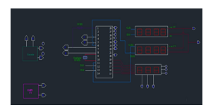
Connection of SMPS plug A and B is to supply power of 5v 5A Encoder have four wire A and B to take power of electrical supply from SMPS and wire C and D is to transfer Data to the controller SMPS supply electric power to the controller at pin no 7 and 8 and data of encoder pulse is given to the controller at pin 4 and 5 and the program is set in the controller. After that the power supply at 5v is given to the displays. Pins of 3 display E Fand G is used to supply the data from the controller Pins E F and G control the points between the digit numbers and pin 1 2 and 3 controls the digits The display no.1 shows the rotation of encoder shaft in 0-360°, the second display shows the count of rotation and the third display shows the movement of tool in mm.
I. Calculation in Program
- Degree = steps x 0.45
- Count = steps / 800
- Distance = steps / 800 x 2 x pi x radius
- Pi = -3.142
- Radius = -0.154
J. Calibration of Encoder
Mount the dial gauge on the tool post of the lathe machine, ensuring that it is perpendicular to the tool axis.
Mount the encoder on the leadscrew of the lathe machine. The encoder will provide feedback on the rotational movement of the leadscrew.
Connect the encoder to a data acquisition system or a Micro Controller. This will allow you to record the linear movement of the leadscrew in real-time.
Rotate the handwheel shaft of the lathe machine by 360 degrees. This will move the leadscrew and the tool post along the length of the lathe bed.
As the tool post moves, hence the transverse axis moves and the dial gauge will measure the displacement of the tool. The encoder will simultaneously record the rotational movement of the leadscrew.
Analyze the data collected by the data acquisition system or micro controller to determine the accuracy of the lathe machine. Calculate the difference between the displacement measured by the dial gauge and the rotational movement recorded by the encoder.
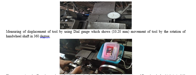
The output given by Encoder as shown by displays, the first display indicates the rotation of Encoder shaft which is in 360 degree. The second display indicates the count of rotation of Encoder shaft. The third display indicates the axis movement of tool which is (10.20 mm).
Hence , the above figures proved the measurement taken by Dial gauge and the reading displayed by Encoder is same without any error.
III. RESULTS
The system successfully monitors the lead screw's rotation in real-time and controls the movement of the tool based on the rotation count of the encoder. The set program is displayed on the third display, and the rotation and count of the rotation of leadscrew displayed on the first and second displays, respectively.
The system's accuracy is evaluated by comparing the actual cut of the tool to the set program. The results show that the system provides precise and efficient cutting.
Table 1: Measurement of movement of tool
|
Measurement by Dial gauge (mm) |
Display 1 Rotation of Leadscrew (Degree) |
Display 2 Count of rotation |
Display 3 Transverse Axis Movement of tool (mm) |
|
1 mm |
35 |
0 |
1mm |
|
2 mm |
70 |
0 |
2 mm |
|
3 mm |
105 |
0 |
3 mm |
|
4 mm |
141 |
0 |
4 mm |
|
5 mm |
176 |
0 |
5 mm |
|
6 mm |
211 |
0 |
6 mm |
|
7 mm |
247 |
0 |
7 mm |
|
8 mm |
282 |
0 |
8 mm |
|
9 mm |
317 |
0 |
9 mm |
|
10.20 mm |
360 |
1 |
10.20 mm |
Conclusion
The real-time monitoring system of transverse axis movement of lathe machine tool presented in this paper is an efficient and accurate way to monitor the rotation of the lead screw in a lathe machine. The use of a rotary encoder and an Arduino board enables precise control of the transverse axis tool\'s movement, resulting in efficient and accurate cutting. Future work can include expanding the system to monitor multiple lathe machines simultaneously and integrating the system with Microcontroller for automation and remote monitoring.
References
[1] D. G. Kopaniza, A. M. Ustinov, N. A. Popova, S. A. Porobova, A. I. Potekaev, G. I. Tayukin and A. A. Klopotov “Study of peculiarities of changes in stress fields of the muff coupling surface of reinforcing bars at its manufacturing” [2] Antonio Ramon Jimenez Ruiz 1, Jorge Guevara Rosas 1 “A Real-Time Tool Positioning Sensor for Machine-Tools” [3] Sara Freunda, Azhar Zamb, Georg Rauter “Proof of concept of a novel absolute rotary encoder” [4] Hyuno Kim,Yuji Yamakawa and Taku Senoo “Robust and precise measurement method of rotation angle via high-speed RGB vision” [5] Alisher Shakirovich ,Ismailov Zafar , Botirovich Jo‘rayev “Study of arduino microcontroller board” [6] PaolaAntonelli, Hernando Barragán, John! Bennett, Dr. Julian Bleeker, Dr. Jan Borchers “ New Art, Design as an open source programmable tools to create interactive works” [7] Dr Andrzej Nowrot,Dr Barbara Solecka “Arduino module to research in surface physics” [8] Muhammad Prayadi Sulistyanto, Politeknik Makatronika Sanata Dharma, Yogyakarta,Indonesia “Design of 4 digit Count Up with 7 Segment 5 Inch [9] Wood, Vincent. “Numitron Readout: Simplified Seven-Segment Display in One Tube.” Decode System. [10] Seven-Segment, LED Display, Common Anode/Cathode, Drivers, LDS-C303RI, CD74HC4511E [11] “Analysis and Implementation of Switch Mode Power Supplies in MHz Frequency Region” Abdul Majid [12] Abraham Pressman, Keith Billings, Taylor Morey “Switching Power Supply Design”, third edition.
Copyright
Copyright © 2023 Prof. R. R. Chavan , Prof. H. K. Shete , Sayyad M. Ibrahim N, Bagwan M. Saad, Mujawar M. Kaif A., Jadhav Somnath S., Mane Pavan A.. This is an open access article distributed under the Creative Commons Attribution License, which permits unrestricted use, distribution, and reproduction in any medium, provided the original work is properly cited.

Download Paper
Paper Id : IJRASET51779
Publish Date : 2023-05-08
ISSN : 2321-9653
Publisher Name : IJRASET
DOI Link : Click Here
 Submit Paper Online