

Ijraset Journal For Research in Applied Science and Engineering Technology
Report on Automatic Vehicle Control System Using IR Technology
Authors: Arnab Nilanjan Roy, Amruth V S, Faiza Aftab
DOI Link: https://doi.org/10.22214/ijraset.2022.44908
Certificate: View Certificate
Abstract
The purpose of this idea is to control the speed of vehicles in relation to the different areas in which they are operating. Areas are generally classified into three types, namely, local narrow roads in a city, heavy traffic wide roads, and outlying roads. The speed limit of vehicles varies depending on the area. By setting special types of transmitters at a frequency of 38 kHz, which are mounted in each area, the speed control task is accomplished. An Infrared Signal (IR) receiving unit is set up in the vehicle which gets activated once it comes into the radiation zone of the transmitters that continuously radiate IR coded signals. The vehicle receives IR radiation whenever the vehicle\'s speed is not within the prescribed speed range and then the speed is controlled either by a control unit or manually. Speed is maintained until the vehicle receives another IR signal. This idea has the potential to be very useful in preventing vehicular accidents. It can also protect pedestrians from overspeed vehicles in slow-moving areas as they cross the road. Consequently, it can be implemented to monitor and control the speed of vehicles in various areas.
Introduction
I. INTRODUCTION
This idea is concerned with monitoring and controlling the speed of vehicles using an IR transmitter and receiver module depending on the area in which the vehicle is moving. The transmitter module can be installed in different areas, specially school zones, hospital zones, highways, sharp turns, U-turns, etc. The receiving unit is installed in the vehicle. The transmitter transmits IR signals which are received by the receiver module, further the speed is controlled based on the signals received. While the vehicle is in the transmitter's range, it receives IR signals when the speed goes beyond the limit and then the speed is controlled and kept in the desired limit till the next IR signal is received.
II. BACKGROUND IDEA
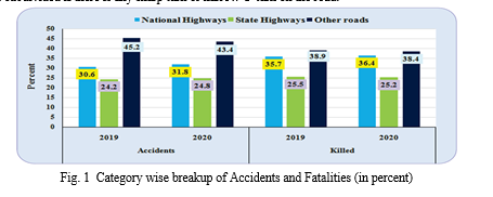
A large number of accidents take place due to careless and over speed driving of vehicles on the road. Almost 1.3 million people die each year in road accidents, so, it is very much required to come up with a solution to this problem. Apart from the deaths taking place in road accidents, a lot of people get badly injured and are unable to do day-to-day activities in a normal fashion for either a long period of time or their whole life. By reducing and eventually stopping reckless driving, this catastrophe can be eliminated. It can be achieved by dividing the areas into different categories, such that the automobiles are forced to maintain their velocity in the specified range of that particular area and thus the drivers cannot accelerate their automobile’s speed beyond the safe limit of a zone. Broadly the areas can be classified into three kinds: local narrow roads in a city, heavy traffic wide roads, and outskirts roads, however, further the areas or zones can be subdivided if there is any public place like a school, hospital, crowded market, etc. nearby. It can also be subdivided if there is any sharp turn or narrow U-turn on the road.
A. Problem Statement
Some particular roads in every state or country deal with heavy traffic throughout the year and they are more prone to road accidents as compared to other roads. To maintain a convenient and safe automobile operation in these zones, certain speed limits can be set. Similarly, there must be some speed limit for automobiles moving in areas nearby schools, hospitals, markets, etc. to avoid road accidents and keep the drivers as well as the pedestrians safe. A city can be divided into specific zones and some automobile speed limit can be established for that particular zone, such that vehicles are forced to operate below that speed even if they try to go beyond the limit.
B. Objectives
The main objectives of this concept are the following:
- Ensuring that the roads are safer for people and eliminating the problem of road accidents.
- Controlling reckless, careless and over speed driving.
- Keeping special zones like school and hospital zones totally safe from accidents by maintaining an automobile speed set by government authorities for these zones.
C. Methodology
The flow of controlled followed for this concept is as follows:
- Understanding the working principle of an IR transmitter and receiver module by studying similar papers/journals..
- Designing the circuit according to the problem statement and then verifying the circuit using a prototype.
- Calculating and verifying the efficiency for large-scale purposes.
III. WORKING
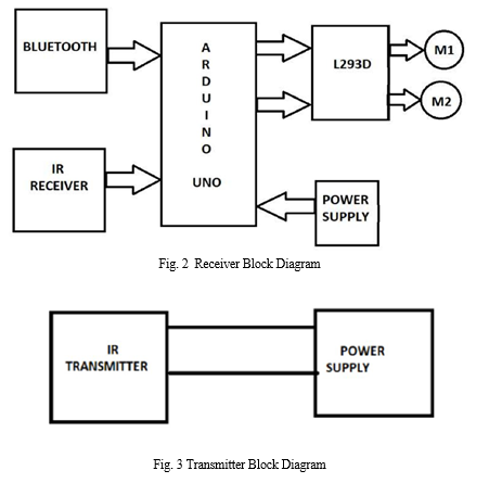
A. Transmitters and Receivers
The block diagram shows the transmitter which is at the edges of the speed limiting areas on both sides. The information needed to decide the vehicle speed, based on its needs, is contained in that unit. To transmit information through IR transmitters to multiple receivers an Arduino module is used.
B. DC Motors
Three possible ways of varying the speed of DC motor:
- Mechanical Gears: Gears are used to vary speed and torque, with different gear ratios.
- Series Resistors: Reducing motor voltage with series resistors. However, due energy wasted in the resistor and reduced torque, this method is highly efficient. Motor will draw more current as the load increases, which leads to larger voltage drop across the series resistor and hence less voltage across the motor. The motor will now draw even more current resulting in motor “stalling”.
- Pulse Width Modulation(PWM): Full voltage is supplied to the motor but in bursts or pulses, eliminating the series drop effect. Shorter pulses will run the motor slowly and longer pulses will make the motor run faster.
DC motor can provide high starting torques which is required for traction drives. DC motor being controlled by voltage supply lets us control over a wide range of speed, both above and below the rated speed. DC speed control methods are also simpler and less expensive than alternating current motors. This plan achieves speed control using PWM, which is generated using a microcontroller.
???????C. Working Principle of PWM
Pulse width modulation (PWM) is a method for binary signals generation which has 2 signal periods- high and low. The width (W) of each pulse varies between 0 and period (T). The main principle is control of power by varying the duty cycle. Here the conduction time to the load is controlled. Let for a time t1 the input voltage appears across the load i.e. ON state and for t2 time the voltage across the load is zero.
The average voltage at output is given by
Va=Vmax x la
Here,
Ton =Time period for Pulse ON,
Toff =Time period for Pulse OFF
The average load current la = Va/R = kVs/R .
Total time period, T=tl + t2,
Duty cycle, k = tl/T
- The duty cycle can be varied from 0 to 1 by varying tl, T or f. Therefore, the output voltage VO can be varied from 0 to Vs by controlling k, and the power flow can be controlled.
- As the time tl changes the width of pulse is varied and this type of control is called pulse width modulation (PWM) control.
For better understanding of PWM these diagrammatic representations can be used. These figures represent the waveforms obtained as output at different voltage requirements.
The speed control is achieved by replacing the digitalWrite function, on the L293D enable pin, with analogWrite. A value between 0 and 255 can be passed to the analogWrite function to control the speed of the motor. Value passed between 1 and 254 will control the speed accordingly.
???????D. Overall Working Principle
A wireless connection is established using IR transmitter and receiver module. The voltage regulator circuit is powered by a 9V battery, which also provides regulated voltage to the motor. The Arduino, motor driver and the receiver modules are powered by a 5V regulated supply.
DC motor is interfaced with a motor driver. Every transmitter at different zone has a particular frequency. When the IR receiver receives a transmitted frequency, the speed code of that particular frequency drives the motor to adjust its speed according to the zone provided. Every time a signal is received, the speed of the vehicle is maintained at a cutoff according to the signal, until the next signal is received.

IV. ACKNOWLEDGMENT
This study was supported by the department of Electrical and Electronics engineering of RNS Institute of Technology, Bengaluru, Karnataka, India.
Conclusion
Automatic Vehicle Control System using IR Technology is an infrared based speed control system that aims to keep the speed of a vehicle within a limit, depending on the zone in which it is operating. The IR transmitter and receiver module are used to establish wireless connectivity. The transmitters are assembled in various areas and they send signals that are received by the receivers that are installed in the vehicles. The input given to the receiver forces the motor to adjust its speed in relation to the speed of that zone. According to the zones, different frequencies of output from the transmitter is given out and received by the receiver. This specific frequency causes the motor to adjust its speed and the vehicle is kept at a cut-off based on the given signal, until the next signal is received.
References
[1] Shuvo, Md Moinuddin & Munira, Fatema & Akash, Mehedi & Debnath, Sukanta. (2017). Automatic Vehicle Speed Reduction System Using RF Technology & Accident Prevention system. 10.13140/RG.2.2.29494.70722. [2] Shiny, Lorate et al. “Vehicle Control System with Accident Prevention by Using IR Transceiver.” (2015). [3] A. Vengadesh, K. Sekar. \"Autonuatic Speed Control of Vehicles in Restricted Areas Using RF and GSM\", ME Embedded Systems, ECE, Kongu Engineering College, Erode, India. [4] Amulya A M. Karuna C V. \"Intelligent Vehicle Speed Controller\", UG Students, Dept of ECE, National Institute of Engineering Mysore. [5] www.engineersgarage.com/speed-control-using-pwm-modulation/ www.researchgate.net/publication/307600931_Study_of_DC_motor_and_its_speed_control_by_pulse_width_modulation_technique
Copyright
Copyright © 2022 Arnab Nilanjan Roy, Amruth V S, Faiza Aftab. This is an open access article distributed under the Creative Commons Attribution License, which permits unrestricted use, distribution, and reproduction in any medium, provided the original work is properly cited.

Download Paper
Paper Id : IJRASET44908
Publish Date : 2022-06-26
ISSN : 2321-9653
Publisher Name : IJRASET
DOI Link : Click Here
 Submit Paper Online