

Ijraset Journal For Research in Applied Science and Engineering Technology
Road Survey by using Total Station and Design of Flexible Pavement
Authors: Pradyumna Sahoo, Srichandan Sarangi, Jeeban Ku. Mallik, Anima Tirkey, Chitrabhanu Sahoo
DOI Link: https://doi.org/10.22214/ijraset.2023.54375
Certificate: View Certificate
Abstract
In the current scenario the growth of a nation is totally depends upon the road infrastructure and connectivity of that nation. So, at the same time it’s equally important to construct sustainable and environment friendly roads in the country. This study compares the applications of novel surveying technologies for road surface mapping by total Stations and design of flexible pavement by using IIT pave. This project is on GIFT college Gate to Khordha - Chandaka Road. This is the road that connect our college and it is around 300 m stretch. In particular, a Leica TCRP 1203 instruments was used for surveying. This study deals with issues of road surveying under light traffic condition, the safety of surveyors, work methodology, optimization of surveying time, traffic volume study during 8.00-9.00am and 3.30-4.30pm. The aspects of data processing, assessment, traffic analysis, flexible pavement design as per IRC:37-2018 are also handled. Possible reasons for detected discrepancies between different approaches are discussed in detail. The methods in question both allow the accurate determination of paving material volumes that should be milled off the upper layer of the road surface and the volume of the filling material required to achieve a smooth road surface. However, this study evaluates the use of conventional surveying methods such as total station surveying in road surface mapping and design of flexible pavement (code IRC: 37) as well as the material evaluation. Now-a-days, handling the waste from different industry is a challenge. So, this study also evaluates the sustainability of waste material to construct the flexible pavement inside the college campus. Software used IIT pave, AutoCAD, Staad Pro.
Introduction
I. INTRODUCTION
The purpose of this report is to present the design of a flexible pavement for a bike parking based on a survey and analysis conducted in a particular area. The report outlines the finding of the survey, analysis, and design process, including the methodology, materials and standards used. The final design is based on the results of the survey and analysis, taking into consideration the anticipated traffic volumes, environmental condition, and local regulations.
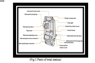
- The Total station is designed for measuring of slant distances, horizontal and vertical angles and elevations in topographic and geodetic works, tachometric surveys, as well as for solution of application geodetic tasks. The measurement results can be recorded into the internal memory and transferred to a personal computer interface.
- The basic properties are unsurpassed range, speed, and accuracy of measurements. Total stations are developed in view of the maximal convenience of work of the user. High-efficiency electronic tachometers are intended for the decision, It has the broad audience for sole of industrial problems.
- Angles and distances are measured from the total station to points under survey, and the coordinates (X, Y, and Z or northing, easting, and elevation) of surveyed points relative to the total station position are calculated using trigonometry and triangulation.
- Data can be downloaded from the total station to a computer and application software used to compute results and generate a map of the surveyed area.
- A total station is an electronic/optical instrument used in modern surveying. It is also used by archaeologists to record excavations as well as by police, crime scene investigators, private accident Reconstructionist and insurance companies to take measurements of scenes. The total station is an electronic theodolite (transit) integrated with an electronic distance meter (EDM), plus internal data storage and/or external data collector.
- The purpose of any survey is to prepare maps, control points formed a basic requirement for the preparation of these maps.
- There are several numbers of methods like traverse, triangulation etc., to provide these control points.
- Whatever the method the provision of control points, includes the measurement of two entities (Distance and Angle).
- Again, distance can be measured by using various instruments like chain, tape.
- Linear Tap.
- Gunter’s chain (20m and 30m).
- Steel band (20m and 30m).
- Inver tap.
- Hunter Short Base (80m).
- Electronic Distance Measurement Instruments, Total station, and GPS.
- Angle can be measured by using a THEODOLITE.
- Once distance and angular measurement is over computation is performed to provide the control points. A combination of all the three results in a powerful instrument called TOTAL STATION. Hence, the TOTAL STATION is an instrument which consists of the following
a. Distance measuring instrument (EDM).
b. An angle measuring instrument (Theodolite).
c. A simple microprocessor.
II. FUNCTION PERFORMED BY T.S
Total Stations, with their microprocessors, can perform a variety of functions and computations, depending on how they are programmed. The capabilities vary with different instruments, but some standard computations include:
- Averaging multiple angle and distance measurements.
- Correcting electronically measured distances from prism constant, atmospheric pressure, and temperature.
- Making curvature and refraction corrections to elevations determine by trigonometric levelling.
- Reducing slope distances to their horizontal and vertical components.
- Calculating point elevations from the vertical distance components (supplemented with keyboard input of instrument and reflector heights).
- Computing coordinates of survey points from horizontal angle and horizontal distance.
a. Averages multiple angle measurements.
b. Averages multiple distance measurements.
c. Computes horizontal and vertical distances.
d. Corrections for temp, pressure, and humidity.
e. Computes inverses, polars, resections.
f. Computes X, Y and Z coordinates.
Because the Total Station contains delicate electronic components they are not as rugged as ordinary Theodolite. They must be packed and transported carefully, handled gently and carefully removed from their cases.
The setting of Total Station over the station mark is similar to an ordinary Theodolite. This includes
- Centring
- Levelling
- Removal of parallax
Total Stations are controlled with entries made either through their built-in keyboards or through the keyboards of hand-held data collectors. Details for operating each individual total station vary somewhat and therefore are not described here.
The accuracy achieved with total station is mainly depends on operator procedure of Careful centering and levelling of the instrument
- Accurate pointing at targets.
- Taking averages of multiple angle measurements made in both direct and reverse positions Peripheral equipment that can affect accuracy includes
- Tribrachs
- Optical plummets
- Prism and
- Prism poles
Tribrachs must provide a snug fit without slippage. Optical plummets that are out of adjustment cause instruments to be set up erroneously over the measurement point. The prism poles should be perfectly vertical and prism should be well fitted on that. Prisms should be checked frequently to determine their constants.
III. APPLICATIONS OF T.S
There are many other facilities available, the total station can be used for the following purposes.
- Detail survey i.e., data collection.
- Control Survey (Traverse).
- Height measurement (Remove elevation measurement- REM).
- Fixing of missing pillars (or) Setting out (or) Stake out.
- Resection.
- Area calculations, etc.
- Remote distance measurement (RDM) or Missing line measurement (MLM).
IV. OBJECTIVES AND REQUIREMENTS OF THE PAVEMENT
- The soft piece of equipment should we stable and non-yielding, to allow the heavy wheel load of the road traffic to move with last possible rolling resistance.
- The road should be even along the longitudinal profile to enable the first vehicles to move safely and comfortably at the design speed.
- A pavement layer is considered more effective or superior, if it is able to distribute the wheel load stress through a larger area per unit death of the layer.
- Elastic deformation of the pavement should be within the permissible limits so that the payment can sustain a large number of repeated Lord applications during the design life.
- It is always desirable to construct the payment well above the maximum level of the groundwater to keep the subgrade relatively dry even during monsoons. At high moisture contents the soil becomes weaker and sort and starts yielding under heavy wheel loads, thus increasing the tractive resistance.
V. TYPES OF PAVEMENTS
Based on the structural behaviour, pavements are generally classified into the following three categories:
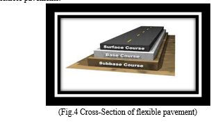
A. Flexible Pavement
Flexible pavements are those which are flexible in their structural action under the loads. Some important pictures of these pavements are.
- It has no flexural strength.
- It reflects the deformation of lower layer.
- It will transmit the vertical compressive stress to bottom layers by grain-to-grain transfer,
- The lower layer has to take up only lesser magnitudes of stress and there is no direct wearing action due to traffic loads, therefore inferior materials with low cost can be used in the lower layers.
Flexible pavements consist of the following components:
a. Soil sub grade
b. Sub base course
c. Base course
d. Surface course
Bituminous concrete, granular materials with or without bituminous binder, WBM, soil aggregate mixes etc.., are common examples of flexible pavements.
Flexible pavements are commonly designed using empirical chart or equations. There are also semi empirical and theoretical methods for the design of flexible pavements.
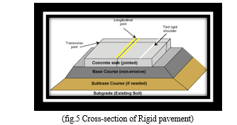
B. Rigid Pavement
Rigid pavements are those which possess noteworthy flexural rigidity.
- It possesses flexural strength.
- Load transfer is by the way of slab action and it distributes the wheel load to a wider area below
- Flexural stresses will be developed due to wheel load temperature changes
- Tensile stresses will be developed due to bending action of the slab under the wheel load
- It does not deform to the shape of lower layer, but it bridges the minor variations of the lower layer.
Rigid pavement consists of the following components:
a. Cement Concrete slab
b. Base course
c. Soil sub grade
Rigid pavements are made of Portland cement concrete either plain, reinforced or prestressed. The plain cement concrete is expected to take up about 40kg/cm2 flexural stress. These are designed using elastic theory, assuming the pavement as an elastic plate resting over an elastic plate resting over an elastic or viscous foundation.
C. Semi-Rigid Pavement
Wheel bonded materials like pozzolanic concrete, lean concrete or soil cement are used, then the pavement layer has considerably high flexural strength then the common flexible pavement is called a semi- rigid pavement.
These materials have low resistance to impact and abrasion and are therefore used with flexible pavement surface course.
VI. FUNCTION OF PAVEMENT COMPONENTS
A. Soil Subgrade
- The pavement load is ultimately taken by soil sub grade and hence in no case it should be over stressed and top 50cm layer of soil sub grade should be well compacted at O.M.C.
- Common strength tests used for evaluation of soil sub grade are:
a. California bearing ratio test
b. California resistance value test
c. Triaxial compression test
d. Plate bearing test
B. Sub Base And Base Courses
- These are broken stone aggregates. It is desirable to use smaller size graded aggregates at sub base course instead of boulder stone.
- Base and sub base course are used under flexible pavement primarily to improve load supporting capacity by distribution of load through a finite thickness.
- Base courses are used under rigid pavements for:
a. Preventing pumping
b. Protecting the sub grade against frost action
C. Wearing Course
- Purpose of this course is to give smooth riding surface. It resists pressure exerted by tyres and takes up wear and tear due to traffic. It also offers water tightness.
- The stability of wearing course is estimated by Marshalling stability test where in optimum percent of bituminous material is worked out based on stability density, voids in mineral aggregate (V M A) and voids filled with bitumen (V F B). Plate Bearing test are also sometimes made use for elevating the wearing course and the pavement as a whole.
VII. FACTORS TO BE CONSIDERED IN THE DESIGN OF PAVEMENTS
Pavements design consists of two parts:
- Mix design of material to be used in each pavement component layer
- Thickness design of the pavement and the component layer
The various factors to be considered for the design of pavements are:
a. Design wheel load
b. Sub grade soil
c. Climatic factors
d. Pavement component material
e. Environment factors
f. Special factors in the design of different types of pavements
VIII. DESIGN OF FLEXIBLE PAVEMENT
Various approaches for flexible pavement design may be classified into three broad groups:
- Empirical method:
a. These are based on physical properties and strength parameters of soil sub grade.
b. The group index method, CBR method, Stabilimeter method and Mc load method etc…., are empirical methods.
2. Semi empirical methods or semi theoretical methods: These methods are based on stress strain function and experience.
3. Theoretical methods: These are based on mathematical computations. For example, Burmister method is based on elastic two-layer theory.
IX. GROUP INDEX METHOD
D.J Steel suggested the thickness requirements with the Highway Research Board method based on the group index values in 1945. Group index value is an arbitrary index assigned to the soil types in numerical equations based on the percent fines, liquid limit and plasticity index.
GI values of soil vary in the range of 0 to 2. The higher the GI value, weaker is the soil sub grade and for a constant value of traffic volume, the greater would be the thickness requirement of the pavement.
The traffic volume in this method is divided into three groups:
|
Traffic volume (commercial vehicles) |
No. of vehicles / day |
|
Light |
Less than 50 |
|
Medium |
50 to 300 |
|
Heavy |
Over 300 |
X. DESIGN STEPS
Initially, the group index value is calculated for the soil sub grade based on the following formula:
GI = 0.2a + 0.005ac + 0.01bd
Where,
a = percentage of material passing through IS 200 (0.075mm) sieve, is more than 35 and less than 75 (0 to 40)
b = percentage of material passing through IS 200 (0.075mm) sieve, is more than 15 and less than 55 (0 to 40)
c = liquid limit more than 40 and less than (0 to 20)
d = plasticity index more than 10 and less than 30 (0 to 20)
XI. CALIFORNIA BEARING RATIO METHOD
- In 1928, California divisions of highways in USA developed CBR method for pavement design. The majority of curves developed later are based on the original curves developed by O.J. Porter. At the beginning of second world war, the corps engineer of USA made a survey of the existing method of pavement design and adopted CBR method for designing military airport pavements. One of the chief advantages of CBR method is simplicity of the test procedure.
- Most of the road pavements designed in CBR method on the CBR value of subgrade soil determined by conducting CBR test in the laboratory on the sub grade soil disturbed or remoulded depending on whether an existing sub grade is utilized for the pavement without improvement or a new sub grade is to be constructed with proper control over its properties, especially compaction characteristics.
- CBR value is defined as the ratio of load required to cause a specified penetration, say 2.5mm or 5mm of a standard plunger into the sample to the load required to produce the same penetration of same plunger into standard stone aggregate sample, expressed as a percentage.
- CBR value varies from 0 to 100%. More CBR indicates the stronger soil. If density is less, CBR is less. The CBR is expressed as percentage of penetration resistance of a given pavement material to that of a standard value of penetration resistance obtained for a crusher stone aggregate available in California.
- The thickness of the pavement is then obtained from the CBR value using the charts provided.
XII. DESIGN OF PAVEMENT USING CBR METHOD: IRC
- CBR test should be performed on remoulded soils in laboratory, in-situ tests are not recommended for design purpose.
- The soil should be compacted at OMC to proctor density.
- Test samples should be soaked in water for 4 days period before testing. However, in dry zone (<50cm rainfall) it is not necessary to soak.
- At least three samples should be tested on each type of soil at the same density and moisture content. If variation is more than permissible value, an average of six samples should be considered.
|
Permissible variations |
CBR (%) |
|
3% |
Upto 10% |
|
5% |
10 to 30% |
|
10% |
30 to 60% |
5. The top 50cm of sub grade should be compacted at least up to 95 to 100% of proctor density.
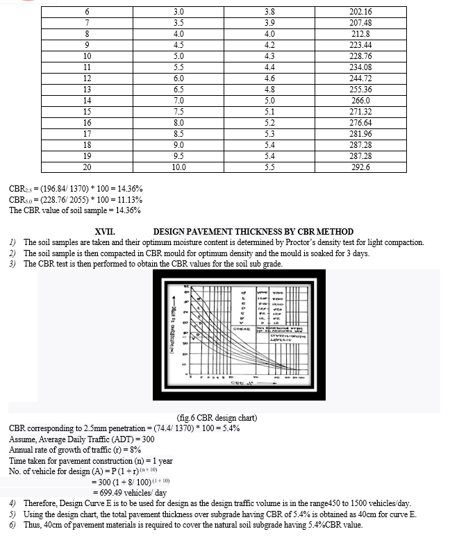
6. Following formula may be used in case estimating future heavy vehicles in view of growth rate for design:
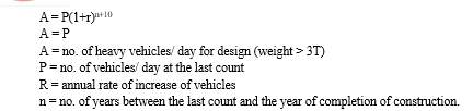
7. The design thickness is considered applicable for single axle loads up to 8200 kg and tandem axle up to 14500 kg for higher axle loads, the thickness is further increased.
8. When sub base course material contains substantial proportion of aggregate size above20mm, the CBR value of the material would not be valid for the design of subsequent layers above them.
XIII. LIMITATION
The CBR method gives the total thickness requirement of the pavement above a subgrade and this thickness value would remain same irrespective of the quality of materials used in the component layers. Thus, the component of materials should be judiciously choosen for durability and economy.
ESTIMATION:
- An estimation is a computation or calculation of the qualities required and expenditure likely to be incurred in the construction of a work. The primary objective of estimate is to enable one to know beforehand the cost of the work.
- For all engineering works, it is desirable to know beforehand the probable cost of construction known as estimated cost. If the estimated cost is greater than the money available, then attempts are made to reduce the cost by reducing the work or changing the specifications. In preparing the estimate, the quantities of different items of work are calculated by simple mensuration method and from these quantities, the cost is calculated.
- Accuracy in estimate is very important, if an estimate is exceeded, it becomes a very difficult problem for the engineers to explain, to account for and arrange for the additional money. Inaccuracy in preparing of estimate, omission of items, changes in design, improper rates etc.., are the reasons for exceeding the estimate, though increases in rate is also one of the main reasons.
- The rate of each item should be reasonable and workable. The rates in the estimate provide for the complete work, which consists the cost of the materials, cost of labour, cost of tools and plants, cost of water, taxes, establishment, supervision cost, reasonable profit of contractor etc...,
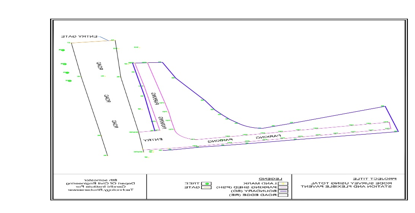
XIV. OVERVIEW OF SURVEY WORK
- The project area is the parking lot close to Main gate, Gift college. First, reconnaissance of the project area has been performed, and followed by establishing a network of 14 control points, which have been used as a reference value for the detail survey. The network has been established using Leica 1201 version total station.
XV. METHODOLOGY FOR PAVEMENT DESIGN
A. Collection of Samples
Three samples of soils had been collected in the location of the site (work).
B. Types of Tests
The different types of tests conducted on the samples are:
- Index Properties
a. Liquid limit
b. Plastic limit
c. Specific gravity
d. Sieve analysis
2. Engineering Properties
a. Standard Proctor test
XVI. CALIFORNIA BEARING RATIO (CBR) TEST
The CBR test is a penetration test developed by the California division of highways, as a method evaluating the stability of soil sub-grade and other flexible highway materials. The test results have been correlated with the pavement thickness requirements for highways and airfields. The CBR test may be conducted in the laboratory on a prepared specimen in a mould or in-situ in the field.
Procedure
- About 5kg of oven dried soil sample is taken and is mixed with optimum moisture content. The soil is then compacted either by IS light compaction (3 layers, 55 blows, each by 2.6 kg hammer) or IS heavy compaction (5 layers, 55 blows, each by 4.89 kg hammer).
- The mould with the base plate is placed under the penetration plunger of the loading machine and a surcharge weight of 2.5 kg is applied.
- The dial gauge for measuring the penetration values of the plunger is fitted in position. The dial gauge of the proving ring and the penetration dial gauge are set. The load readings are recorded at penetration readings of 0.0, 0.5, 1.0, 1.5, 2.0, 2.5, 3.0, 3.5, 4.0,4.5, 5.0, 5.5, 6.0, 6.5, 7.0 etc.
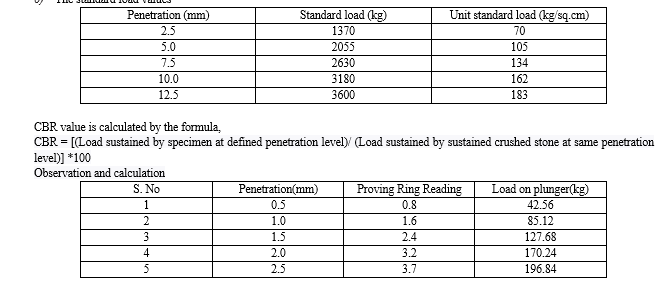
- The proving ring calibration factor is noted. The load penetration curve is the plotted. The unit load values corresponding to 2.5mm and 5.0mm penetration values are found from the graph.
- This load is expressed as a percentage of standard load values at the respective deformation level to obtain the CBR value. The CBR for 2.5mm penetration is taken.
- The standard load values

Conclusion
1) In this project work, an attempt is made to incorporate latest techniques of geometric design, pavement design for a bike parking which lies within the premises of GIFT college, BBSR. The IRC specifications are based on rational thinking, the proposed design is safe in both geometrics as well as pavement design. 2) It is also proposed to design a flexible pavement by Group Index method and CBR method. Some more methods are available in the design of flexible pavement, which are much advanced like California resisting value method, Mc leod method, Triaxial method and Burnister method. Because of the limitations of time and scope, only GI method and CBR method are adopted. 3) To have a practical concept of estimation analysis, an attempt is made to estimate the quantities of each work of flexible pavement. 4) Today total station (TS) is used for many tasks within different applications, for example, geodesy, engineering, architectural and mining surveys and documentation of cultural heritage with different accuracy level depending on the needed requirements. 5) The purpose of this is work was to evaluate and compare accuracy, precision and time expenditure of total station surveying method. 6) The project area is the parking lot close to Main gate, Gift college. To accomplish the objectives of the thesis, three major tasks have been performed. 7) 1. A network of 14 control points was established with high precision (l mm) with total station and served as a reference or established value.
References
[1] Ahmed, E.M. (2012). Performance Analysis of the RTK Technique in an Urban Environment, Australian Surveyor, 45:1, 47-54. [2] Angelo, J.B. (2004), Integration of Laser Scanning and Close-Range Photogrammetry the last decade and beyond, Ottawa, Canada. [3] ANZLIC (Australia and New Zealand Land Information Council), 2006. Glossary: spatial information related terms. Retrieved on March 23, 2013 from http://www.anzlic.org.au/glossary_terms.html. [4] Borgelt S C., Harrison J D., Harrison, K. A. Sudduth, and S. J. Birrell (1996). Evaluation of GPS for Applications in Precision Agriculture; Appl. Eng. Agric. 12(6) 633–638.
Copyright
Copyright © 2023 Pradyumna Sahoo, Srichandan Sarangi, Jeeban Ku. Mallik, Anima Tirkey, Chitrabhanu Sahoo. This is an open access article distributed under the Creative Commons Attribution License, which permits unrestricted use, distribution, and reproduction in any medium, provided the original work is properly cited.

Download Paper
Paper Id : IJRASET54375
Publish Date : 2023-06-24
ISSN : 2321-9653
Publisher Name : IJRASET
DOI Link : Click Here
 Submit Paper Online