

Ijraset Journal For Research in Applied Science and Engineering Technology
Seismic Analysis of Elevated Metro Bridge
Authors: Suresh Tanmane, S. V. Rayadu
DOI Link: https://doi.org/10.22214/ijraset.2022.44595
Certificate: View Certificate
Abstract
A metro rail system is more preferred type of metro system due to ease of construction and also it makes urban areas more accessible with very less construction difficulty. metro concept is very easy to transport large numbers of people and transportation. In metro city like Delhi, Kolkata, Chennai and Mumbai is very populated city An elevated metro system has two major elements pier and box girder. The codes are now moving towards a performance-based (displacement-based) design approach, which consider. All the information are given by MMRC and considered the data value in this design as per the target performances at the design stage. Which is located to ShyamNager metro station in Mumbai, The present study focuses on pier of an elevated metro structural system conventionally the Double Decker pier of a metro bridge is designed using a force based approach. During a seismic loading, the behaviour of a single pier elevated bridge relies mostly on the ductility and the displacement capacity. It is important to check the ductility of such single piers. Force based methods do not explicitly check the displacement capacity during the design. The codes are now moving towards a performance-based (displacement-based) design approach, which consider the design as per the target performances at the design stage. Performance of a pier designed by a Direct Displacement Based Design is compared with that of a force-based designed one. The design of the pier is done by both force based seismic design method and direct displacement based seismic design method the study.
Introduction
I. INTRODUCTION
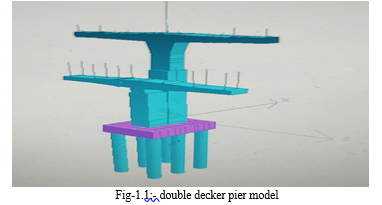
The Metro bridges are analysed the displacement and bending moment and shear force distribution are calculated due to the applied loads. For this, the finite element method further, seismic analysis by the bridge structure is performed on structural analysis software staad pro v8i. An elevated metro system has two major components pier and box girder. A typical elevated metro bridge model is shown in Figure 1.1 (a). Viaduct or box girder of a metro bridge requires pier to support the each span of the bridge and station structures. Piers are constructed in various cross sectional shapes like cylindrical, elliptical, square, rectangular and other forms. The piers considered for the present study are in rectangular cross section and it is located under station structure. Box girders are used extensively in the construction of an elevated metro rail bridge. The tensional and warping rigidity of box girder is due to the closed section of box girder. The box section also possesses high bending stiffness and there is an efficient use of the complete cross section. Box girder cross sections may take the form of single cell. Seismic analysis of Double Decker pier as per strength based method and performance based method. The force based design and displacement analysis for single degree of freedom structure as per IRS 5,16,24, 78, IS 1893 part1:2002 and RDSO guideline -13 The both are performance study of different configuration. A typical Elevated Double Decker pier model show in fig 1.1.
A. Objective
- To study the performance of a double decker pier designed by force based design method and direct displacement based design method.
- Seismic analysis perform on double Decker pier metro bridge for zone-3.
- To find the results Displacement, Bending moment and shear force by finite aliment method to double Decker pier are calculated due to the applied loads
B. Scope
- The present study is limited to these practical case the come cross in an Double Decker pier metro bridge projects.
- With regard to the geometry of the pier considered the present study is limited to.
- Rectangular pier cross section.
- Double Decker pier structural system.
- Reinforcement concrete pier.
II. DESIGN OF PIER
Conventionally the Double Decker pier of a metro bridge is designed using a force based approach. Recent studies (Priestley et al., 2007).The pier height for taller pier effect will be calculated as per ACI 318 to workout additional moments arising. show that the force based design may not necessarily guarantee the required target performances.
The design of a pier by force based seismic design method is carried out as per IS 1893: 2002 Code. The design procedure to find the base shear of the pier by FBD method is summarized below.
- Step 1: The structural geometry of the pier is assumed.
- Step 2: Member elastic stiffness are estimated based on member size.
- Step 3: The fundamental period is calculated by:
T = 0.075 h0.75
Where h = Height of Building, in m.
4. Step 4: Seismic Weight of the building (W) is estimated
5. Step 5: The design horizontal seismic coefficient Ah for a structure determined by
Ah = ???? ???? ???????? 2 ???? ????
Where, Z = Zone factor
I = Importance factor
R = Response reduction factor,
Sa/g = Average response acceleration coefficient Z, I, R and Sa/g are calculated as per IS 1893:2002 Code.
6. Step 6: The total design lateral force or design seismic base shear force (VB) along any principal direction is given by
VB = Ah W
Where Ah = Design Horizontal Seismic Coefficient and
W= Seismic Weight of the Building
A. Perform Study Of A Double Decker Pier
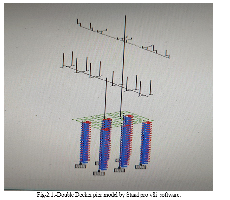
The substructure and superstructure is viaduct generally comprises of simply supported spans. The shape of the pier follows the flow of force .pier gradually wide at the top to support the bearing under the box webs. The pier is rectangular with curve at corners and grooves for aesthetic finish .The longitudinal pier present study is based on the design basis report of the viaduct will be conducted according to the RDSO guideline of 2015 . Limited Performance study displacement of the pier designed by a Force Based Design (FBD) Method and Direct Displacement Based Design (DDBD) Method is described in this chapter. Performance assessment is carried out for the designed pier and the results are discussed briefly. The box girder superstructure shall be constructed with precast by long line /short line method using over head launcher for span 250m radius. For the stress induced in segment during any stage of construction shall not exceed 50% of cube strength .The typical pier models considered for the present study are shown in figure 2.1.
B. Material property
The material property considered for the present pier analysis for concrete and reinforcement steel are given in Table 1
Table 1: Material Property for
- Pier Properties of Concrete Compressive Strength of Concrete = 60 N/mm2
- Density of Reinforced Concrete = 24 kN/m3
- Elastic Modulus of Concrete = 36000 N/mm2
- Poisson’s Ratio = 0.15
- Thermal Expansion Coefficient = 1.17 x 10 -5 / 0C
- Properties of Reinforcing Steel Yield Strength of Steel = 500 N/mm2
- Young’s Modulus of Steel = 205,000 N/mm2
- Density of Steel = 78.5 kN/m3
- Poisson’s Ratio = 0.30
- Thermal Expansion Coefficient = 1.2 x 10 -5 / 0C
C. Design Load
The elementary design load considered for the analysis are Dead Loads (DL), Super Imposed Loads (SIDL), Imposed Loads (LL), Earthquake Loads (EQ), Wind Loads (WL), Derailment Load (DRL), Construction & Erection Loads (EL), Temperature Loads (OT) and Surcharge Loads (Traffic, building etc.) (SR). The approximate loads considered as per MMRC DBR report for the analysis are shown in Table 2. The total seismic weight of the pier is
Table 2: Approximate design load case
|
Load from platform level |
Load |
Load from track level |
Load |
|
Self weight |
120kN |
Self weight |
160KN |
|
Slab weight |
85KN |
Slab weight |
100KN |
|
Roof weight |
125KN |
Total dl |
260KN |
|
Total dl |
330KN |
SIDL |
110KN |
|
SIDL |
155KN |
Train load |
190KN |
|
Crowd load |
80KN |
Breaking +Tractive load |
29KN |
|
LL on roof |
160KN |
Long welded rail forces |
58KN |
|
Total ll |
240KN |
Bearing load |
20KN |
|
Roof wind load |
85KN |
Temperature load |
|
|
Lateral |
245KN |
For track girder |
20KN |
|
Bearing load |
14KN |
Platform girder |
14KN |
|
|
|
Derailment load |
80 kN/m |
The force based design is carried out for Pier as per IS 1893:2002 and IRS CBC 1997 Code and the results are shown in Table 2. From the FBD, it is found out that the minimum required cross section of the pier is only 2m X2.2m m for 0.8 % reinforcement
Table-3.: Approximate design load case
|
Pier type |
Cross section (m) |
Dia. Of bar (mm) |
Number of bar |
Required |
Provided by MMRC |
|
Flyover pier |
2 x 2.2 |
32 |
36 |
0.8% |
1.48 % |
|
Viaduct pier top level |
2 x 2.2 |
32 |
38 |
0.8% |
1.48% |
D. Performance Assessment result
The performance assessment is done to study the performance of seismic analysis is conducted for the designed pier using Saad pro v8i Software Performance parameters Displacement, max shear force max banding moment, behavior are found for both x and z directions and the results are shown in fig 2.4.1 and 2.4.2
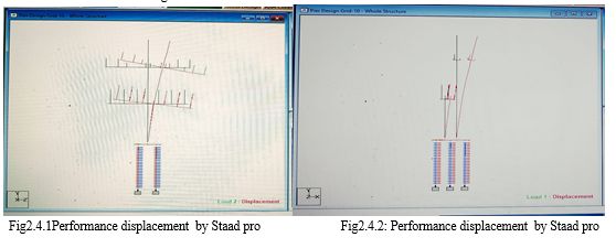
Table-4: Displacement result of double Decker pier
|
z |
|
|
Horizontal |
Vertical |
Horizontal |
|
|
Node |
L/C |
X mm |
Y mm |
Z mm |
|
Max X |
11208 |
1 SLX |
21.324 |
-0.121 |
0 |
|
Min X |
12341 |
2 SLZ |
-0.64 |
-6.324 |
6.043 |
|
Max Y |
5090 |
2 SLZ |
0.18 |
9.697 |
16.316 |
|
Min Y |
5102 |
2 SLZ |
-0.18 |
-9.699 |
16.316 |
|
Max Z |
11208 |
2 SLZ |
0 |
0 |
24.147 |
|
Min Z |
11272 |
1 SLX |
5.791 |
-0.542 |
-0.078 |
|
Max rX |
9001 |
2 SLZ |
0.178 |
9.551 |
18.702 |
|
Min rX |
11526 |
1 SLX |
0.51 |
0.337 |
0.001 |
|
Max rY |
12341 |
1 SLX |
5.847 |
0.116 |
0 |
|
Min rY |
11253 |
2 SLZ |
0.585 |
5.755 |
6.123 |
|
Max rZ |
11542 |
2 SLZ |
0.021 |
-0.337 |
0.562 |
|
Min rZ |
9001 |
1 SLX |
16.431 |
0.331 |
-0.007 |
|
Max Rst |
11208 |
2 SLZ |
0 |
0 |
24.147 |
Conclusion
1) Force Based Design Method may not always guarantee the performance parameter required and in the present case the pier just achieved the target required. 2) In case of find the seismic analysis of double decker perform in selected pier and achieved the behaviour factors by software bases and result get. 3) In this paper parametric study on behaviour of double decker bridge pier of 29.4m high and fly over pier height 21.29m with span 20m both side were analysed using DDBD method as per RDSO:2015. It is observed that behaviour of double decker pier seismic design loading for zone-III . 4) As the span length increases, responses parameter longitudinal stresses at the top and bottom, shear, Displacement, torsion, moment and Deflection are increases . 5) The conclusion can be considered only for selected pier. for generals conclusions large numbers of case studies are required as a scope in future work.
References
[1] I.S. 1893 (2002):“Indian Standard Criteria for Earthquake Resistant Design of Structures Part 1: General Provisions and Bridge”, Bureau of Indian Standards, New Delhi. [2] Jiyang, J., You, B., Hu, M., Hao, J., Li, Y. (2008), “Seismic design of a super high rise hybrid structure”, The 14th world conference of earthquake engineering, October 12-17, 2008, Beijing, China. [3] Pwint Thandar Kyaw Kyaw, (2010) In this study, Pushover Analysis (Static Non-linear Analysis) was carried out, modeling three-dimensional frame buildings located in seismic zone 2A. [4] A. Vijayakumar and D. L. Venkatesh Babu, (2012) concrete bare frame was taken for the investigation. The frame was subjected to design earthquake forces as specified in the IS code for zone III along X and Y directions. [5] Gayatri Sidh1 · Anand Gharad1 (2018) The paper has presented a simple computer-based method for push-over analysis of steel building frameworks subject to equivalent-static earthquake load. [6] V.Kilar and D. Koren, (2008)The paper examines the usage of a simplified nonlinear method for seismic analysis and performance evaluation (N2 method) for analysis of base isolated structures. In the paper the N2 method is applied for analysis of a fixed base and base isolated simple four-storey frame building. [7] Kadid and A. Boumrkik, (2008) In this paper the performance of reinforced concrete frames was investigated using the pushover analysis. [8] STAAD.Pro V8i (2008). Bentley Systems, Inc. Research Engineers, International Headquarters, CA, USA. [9] M.G. Kalyanshetti and C.V. Alkunte, “Study on electiveness of IRC LIVE load on RCR Bridge pier”, International Journal of Advanced Technology in Civil Engineering, Vol. 1(3-4), 2012. [10] R. Tuladhar, H. Mutsuyoshi and T. Maki, “Seismic behavior of concrete bridge pier considering soil pile structure interaction”, The14th World Conference on Earthquake Engineering October 12-17, 2008, Beijing, [11] Standard Drawing (SD 232) The Government of India ,Ministry of Service Transport. [12] IRC:6-2000, “Standard Specifications and Code of Practice for Road Bridge”, Section:II, Loads and stresses. The Indian Road Congress, New Delhi, 2000. [13] IRC:78-2000, “Standard Specifications and Code of Practice for Road Bridges”, Section: VII, Foundations and Substructure. The Indian Road Congress, New Delhi, 2000.
Copyright
Copyright © 2022 Suresh Tanmane, S. V. Rayadu. This is an open access article distributed under the Creative Commons Attribution License, which permits unrestricted use, distribution, and reproduction in any medium, provided the original work is properly cited.

Download Paper
Paper Id : IJRASET44595
Publish Date : 2022-06-20
ISSN : 2321-9653
Publisher Name : IJRASET
DOI Link : Click Here
 Submit Paper Online