

Ijraset Journal For Research in Applied Science and Engineering Technology
Design and Manufacturing Semi-Automatic Machine for Battery Tray Riveting Operation
Authors: Priti Navale, Sarita Padavi, Rohit Patil, Dhiraj Pandit, Prof. R. S. Khandare
DOI Link: https://doi.org/10.22214/ijraset.2023.48851
Certificate: View Certificate
Abstract
The successful implementation of any manufacturing sector is largely depending upon the quality and its productivity. In traditional machining process for performing the one side riveting, machine’s required which becomes a time consuming also the inaccuracy in productivity due to involvement of human error which affects to productivity cannot be get improved at a faster rate. The main purpose of this project to design and manufacture semi-automatic machine for battery tray riveting. Which leads to improve the quality and productivity by minimising the time period in all Mahindra and Mahindra’s vehicles battery is fitted with the help of battery tray. While placing the battery tray two side rivets are required in current situation while fitted tray only one side riveting operation is performed. We are designing a semi-automatic machine which will perform riveting operation to both sides at once which will improve the productivity.
Introduction
I. INTRODUCTION
The latest trend in the automobile industry is to common the production line for different parts. Because now a single vehicle has different variants available in the market for each variant has different components according to their functionality, therefore in the automotive industry it is difficult to maintain multimodal production lines for most of the different parts with the same functionality but a different design for different variations. These processes are very much time consuming and due to which the production losses are observed which leads to delay in vehicle launch, so for this we have fabricated the semi-automatic machine for battery tray riveting. The objective is to design and fabrication of the riveting machine which reduces the operation as well as transportation time required for completing the job. Riveting operation is till now performed manually, but by using semi-automatic Riveting Machine it can be performed automatically. The purpose of this machine is to replace manual hammering into automation, to increase productivity in operation also to reduce cost and time required. It is more beneficial to use in workshops, industries where riveting operations can perform simultaneously on both sides.
II. PROBLEM STATEMENT
In bolero pickup the battery is fitted with the help of battery tray. While placing the battery tray two side rivets are required in current situation while fitted tray only one side riveting operation is performed. We are designing a semi-automatic machine which will perform riveting operation to both sides at once which will improve the productivity.
III. OBJECTIVE
- To DESIGN the semi automation machine for battery tray riveting both sides simultaneously.
- To MANUFACTURE the machine which can rivet both sides of the battery tray simultaneously.
- To ANALYZE the time reduction in process by this automation.
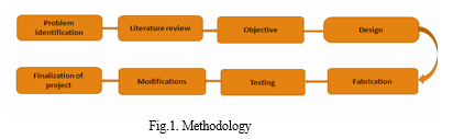
IV. METHODOLOGY
V. DESIGN AND ANALYSIS
A. Material Selection
Mild steel is a type of low carbon steel. Carbon steels are metals that contain a small percentage of carbon (max 2.1%) which enhances the properties of pure iron. The carbon content varies depending on the requirements for the steel. Low carbon steels contain carbon in the range of 0.05 to 0.25 percent.
Due to the following physical properties of Mild steel’s material used for the fabrication of machine:-
- High tensile strength.
- High impact strength.
- Good ductility and weld ability.
- A magnetic metal due to its ferrite content.
- Good malleability with cold-forming possibilities.
- Not suitable for heat treatment to improve properties.
Table no.1: Properties of Material
|
Material |
Density ( Kg/m^3) |
Melting point (°C) |
Modulus of Elasticity (Gpa) |
Thermal Conductivity (Mpa) |
Yield Strength (Mpa) |
Tensile Strength (Mpa) |
Elongat- ion (%) |
|
Mild Steel |
7860 |
1370 |
120 |
42.7 |
345 |
485 |
20 |
|
Aluminum |
2710 |
660.2 |
70 |
88-251 |
240 |
90 |
12.25 |
|
Gray Cast Iron |
7150 |
1204 |
105 |
48 |
- |
250 |
- |
|
Stainless- Steel |
7982 |
1375 |
193 |
16.3 at 100°C |
170 |
485 |
40 |
B. Specification
Table 2. Part specification
|
Sr. No. |
Part name |
Specification/Dimension |
|
|
Rivet head |
Dia. = 155mm |
|
|
Rivet |
Dia. = 7mm |
|
|
Motor |
1 HP |
|
|
FRL unit |
Size – ¼ “ TO 2” |
|
|
Valve |
|
|
5/2 *1/4 solenoid single valve |
Port Size – G ¼” Air flow – 1250 L/M |
|
|
5/2 *1/8” solenoid single valve |
Port Size – G1/8” Air flow – 1250 L/M |
|
|
|
PLC controller |
|
|
SMPS |
I/P = 230VAC, 1.0A O/P = 24VDC, 2.5A |
|
|
PLC |
AC 100-240V |
|
|
MCB |
3 Phase |
|
|
Contactor |
- |
|
|
Relay |
- |
|
|
|
Tube connector |
1/8* M6 |
|
1/8* M8 |
||
VI. ANALYSIS
In this model usually performed a static structural analysis on a geometric model. The performed analysis is same for three different various material. The main focus during entire simulation had observed is that, on how various material changes a value of desired parameter such as total deformation and maximum principle stress. A tested model is on the Ansys Workbench. The Ansys analysis performed on the materials are aluminium, gray cast iron and mild steel from that analysis mild steel is selected for the model development.
A. Head
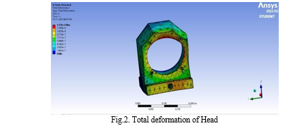
- Total Deformation of Head
It is found that total deformation alone x-axis1.316* 10-6 Maximum. Total deformation generated on mild steel while 1.4622*10-7 Minimum
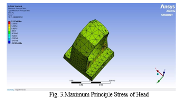
2. Maximum Principle Stress of Head
It is found that Maximum Principle Stress alone x-axis 2.2435*106 Maximum amount of stress generated on mild steel while -3.0162*106 Minimum.
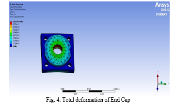
B. End Cap
- Total deformation of End Cap: It is found that total deformation alone x axis1.052* 10-7 Maximum. Total deformation generated on mild steel while 1.1694*10-8 Minimum.
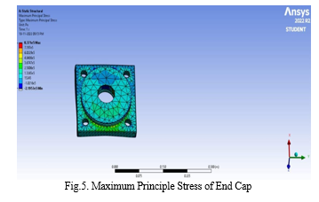
2. Maximum Principle Stress of End Cap: It is found that Maximum Principle Stress alone x-axis 8.371*105 Maximum amount of stress generate on mild steel while -2.1957*105 Minimum.
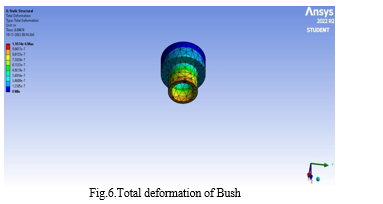
C. Bush
- Total deformation of Bush: It is found that total deformation alone x-axis1.1074* 10-6 Maximum. Total deformation generated on mild steel while 1.2305*10-7 Minimum.
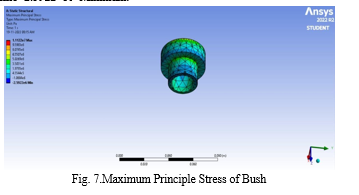
2. Maximum Principle Stress of Bush: It is found that Maximum Principle Stress alone x-axis 1.1122*107 Maximum amount of stress generated on mild steel while -2.5922*106 Minimum.
D. Anti Rotating Plate
- Total deformation of Anti- rotating Plate: It is found that total deformation alone x-axis 6.1183*10-8 Maximum. Total deformation generated on mild steel while 1.3596*10-8 Minimum.
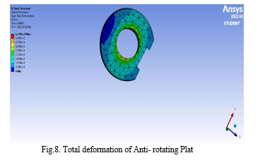
2. Maximum Principle Stress of Anti- rotating Plate: It is found that Maximum Principle Stress alone x-axis 1.1637*106 Maximum amount of stress generated on mild steel while -1.1816*105 Minimum.
VII. RESULT
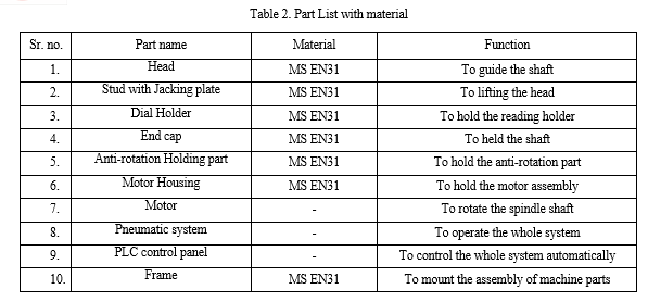
Table 3. Part List with material
|
Part name / Material |
Safe or unsafe |
|||
|
Cast iron |
MS EN31 |
Aluminum |
Gray cast iron |
|
|
Head |
Unsafe |
Safe |
unsafe |
unsafe |
|
Stud with Jacking plate |
Unsafe |
Safe |
unsafe |
unsafe |
|
Dial Holder |
unsafe |
Safe |
unsafe |
unsafe |
|
End cap |
unsafe |
Safe |
unsafe |
unsafe |
|
Anti-rotation Holding part |
unsafe |
Safe |
unsafe |
unsafe |
|
Motor Housing |
unsafe |
Safe |
unsafe |
unsafe |
|
Motor |
- |
- |
- |
- |
|
Pneumatic system |
- |
- |
- |
- |
|
PLC control panel |
- |
- |
- |
- |
|
Frame |
unsafe |
Safe |
unsafe |
unsafe |
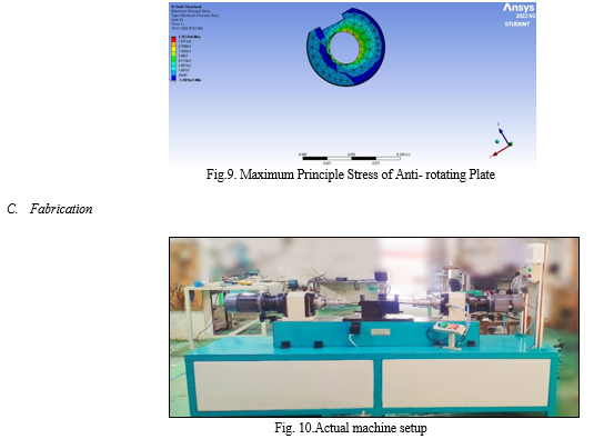
Conclusion
The main purpose of this project to developed semi-automatic machine for battery tray riveting which leads to improve the quality and productivity by minimizing the production cycle time. This machine increases the efficiency and accuracy of object. The machine atomized by using pneumatic system. This machine is to replace manual hammering into automation to increase the productivity in operation to reduce cost and time required. It is more beneficial to use in workshop industry which operation can be perform both sides simultaneously.
References
Reference Books [1] V.B.BHANDARI, design of machine elements, Mc Graw Hill Education, 4th edition. [2] Dr. P.C.SHARMA, a textbook of production engineering, S. Chand publication, 1st edition, 1982. Paper from Conference [1] P. S. Baravkar, D.P.Sonawane, a paper on study & design of multipurpose riveting machine, International SResearch Journal of Engineering and Technology (IRJET), Volume: 04 Issue: 02 | Feb -2017. [3] Andrew Smith and Ian Moore Airbus UK, Ltd., a two tower riveting machine with a true z axis, Paper Number 2004-01-2807. [2] D. A. Mahajan, Dr. S. Y. Gajjal, Design, Fabrication and Analysis of Special Purpose Machine for Drilling and Riveting, International Engineering Research Journal (IERJ) Special Issue 2 Page 2835-2841, 2015, ISSN 2395-1621. [3] Prof. P.R. Sawant, Mr. R. A.Barawade, ?Design and development of SPM - A case study in multi drilling and tapping machine,? IJAERS, Vol. I, E-ISSN2249–8974, Jan-March, 2012. [4] A.G. Hanssen, R. Porcaro, M. Langseth, A. Aalberg, ? The behavior of a self-piercing riveted connection under quasi-static loading conditions”, Department of Structural Engineering, Norwegian University of Science and Technology, Trondheim, Norway,13 Dec 2005. [5] A. M. Takale, V. R. Naik, ?Design & manufacturing of multi spindle drilling head (msdh) for its cycle time optimization?, International journal of Mechanical Engineering applications research, Vol –03, Jan-April 2012. [6] A.S. Aditya Polapragada, K. Sri Varsha, ?Pneumatic Auto Feed Punching and Riveting Machine,? International Journal of Engineering Research & Technology (IJERT) ISSN: 2278-0181, Vol. 1 Issue 7, Sep – 2012. [7] Prof. Tushar A. Patil, & P. N. Ulhe, Analysis and Design of Drilling Cum Riveting Machine. January 2016, Volume 02. Ref: - PSG Design Data. Pg. No: - 1.10 & 1.12. 1.17 [8] Prof. K...G. Sontakke & Prof R. D. Vaidya ,A Review Paper On Design Of Drilling Cum Riveting Machine, November 2014, Volume 01, Issue 06. [9] Prof. Manish Kale & Prof D. A. Mahajan, A Review on Development of Special Purpose Machine .April 2015, Volume 05, Issue 04. [10] Prof. P.R. Savant, Mr. R. A.Barawade JanuaryMarch, 2012, “Design and development of SPM - A case study in multi drilling and tapping machine,” IJAERS, Vol. I, E-ISSN2249–8974. [11] Prof. Sachen Kumar Jagtap & Mukund Kavade Orbital Riveting – A Design & Development of New Machine. 27 April 2014 Volume 02, Issue 04
Copyright
Copyright © 2023 Priti Navale, Sarita Padavi, Rohit Patil, Dhiraj Pandit, Prof. R. S. Khandare. This is an open access article distributed under the Creative Commons Attribution License, which permits unrestricted use, distribution, and reproduction in any medium, provided the original work is properly cited.

Download Paper
Paper Id : IJRASET48851
Publish Date : 2023-01-25
ISSN : 2321-9653
Publisher Name : IJRASET
DOI Link : Click Here
 Submit Paper Online