

Ijraset Journal For Research in Applied Science and Engineering Technology
Implementation of Single-Phase Differential Mode Inverter with Constant Input Power for PV System
Authors: Mr. Ashish Nagrale, Prof. Pooja Sahastrabudhe
DOI Link: https://doi.org/10.22214/ijraset.2022.40087
Certificate: View Certificate
Abstract
A buck-boost ac-ac converter with inverting and non-inverting operations is proposed. The non-inverting operation activity can be utilized to remunerate voltage hang, and altering activity can be utilized to repay voltage swell. Along these lines, the proposed converter as a unique voltage restorer is equipped for making up for both voltage hang and swell in a wide range. It’s essential exchanging cell is a unidirectional buck circuit, inferable from which it has no shoot-through concerns. It accomplishes safe substitution without utilizing RC snubbers or delicate recompense techniques. Further, it tends to be actualized with power MOSFETs without their body diodes directing, and for current freewheeling outside diodes of good converse recuperation highlights can be utilized to limit the opposite recuperation issues and significant.
Introduction
I. INTRODUCTION
For development of intensity quality utilizing DVR, the converter which are commonly utilized are the dc-air conditioning power changes by utilizing thyristor power regulators, which utilize the stage point or fundamental cycle control on input dc voltage, to get the ideal yield air conditioning voltage. Notwithstanding, the conspicuous hindrances of thyristor regulators, for example, low force factor, enormous all out consonant bending in source current and lower proficiency, have restricted their utilization. In this paper, a novel double buck-help air conditioning air conditioning converter is proposed. It joined the tasks of non-altering buck and upsetting buck-support converters in a single structure. Like the buck converter, it has a non-altering buck activity, and like a transforming buck-support converter, it has an upsetting buck-help activity. Also, it has an additional activity, wherein the yield voltage higher or lower than the info voltage that is in-eliminate or of-stage with the information voltage can be acquired. Accordingly, the proposed converter can repay both voltage list and swell when utilized in a DVR.
The fundamental unit of the proposed converter is a unidirectional buck circuit; hence it has no short out and open-circuit issues. It has no recompense issues, and doesn't need lossy snubbers and additionally delicate replacement techniques for activity. Further, it can use MOSFETs without their body diodes directing and without invert recuperation issues and important misfortunes. A buck-help air conditioning air conditioning converter with modifying and non-transforming tasks is proposed. It repays both the voltage hang and swell when utilized as a unique voltage restorer. Its essential exchanging cell is a unidirectional buck circuit, attributable to which it has no shoot-through concerns. It accomplishes safe recompense without utilizing RC snubbers or delicate substitution procedures. Further, it very well may be executed with power MOSFETs without their body diodes leading, and for current freewheeling outside diodes of good opposite recuperation highlights can be utilized to limit the converse recuperation issues and applicable misfortune. The itemized hypothetical investigation and exploratory consequences of a 300-W model converter are given
II. THE DC-DC BUCK -BOOST CONVERTER
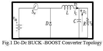
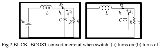
In the description of converter operation, it is assumed that all the components are ideal and also the converter operates in CCM. In CCM operation, the inductor current flows continuously over one switching period. The switch is either on or off according to the switching function q and this results in two circuit states. The first sub-circuit state is when the switch is turned on, diode is reverse biased and inductor current flows through the switch, which can be shown in figure 2(a). The second sub-circuit state is when the switch is turned off and current freewheels through the diode, which is shown figure 2(b).
A. Modes of Operation
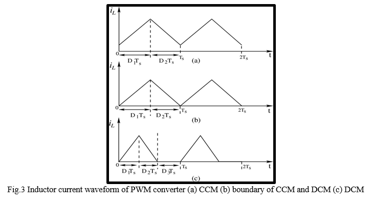
The operation of ac-ac converters can be classified by the continuity of inductor current flow. So dc-dc converter has two different modes of operation that are (a) Continuous conduction mode (CCM) and (b) Discontinuous conduction mode (DCM). A converter can be design in any mode of operation according to the requirement.
- Continuous Conduction Mode: When the inductor current flow is continuous of charge and discharge during a switching period, it is called Continuous Conduction Mode (CCM) of operation shown in fig 3(a). The converter operating in CCM delivers larger current than in DCM. In CCM, each switching cycle TS consists of two parts that is D1TS and D2TS (D1 + D2 = 1).During D1TS , inductor current increases linearly and then in D2TS it ramps down that is decreases linearly.
2. Discontinuous Conduction Mode: An When the inductor current has an interval of time staying at zero with no charge and discharge then it is said to be working in Discontinuous Conduction Mode (DCM) operation and the waveform of inductor current is illustrated in fig 3(c). At lighter load currents, converter operates in DCM. The regulated output voltage in DCM does not have a linear relationship with the input voltage as in CCM. In DCM, each switching. Cycle is divided into of three parts that is D1TS, D2TS and D3TS (D1+D2 + D3=1). During the third mode i.e. in D3TS, inductor current stays at zero.
B. Control methods for Dc-Dc BUCK -BOOST Converter of Operation
Voltage-mode control and Current-mode control are two commonly used control schemes to regulate the output voltage of ac-ac converters. Both control schemes have been widely used in low-voltage low-power switch-mode ac-ac converters integrated circuit design in industry. Feedback loop method automatically maintains a precise output voltage regardless of variation in input voltage and load conditions.
1. Voltage- mode Controlled BUCK -BOOST Converter: The voltage feedback arrangement is known as voltage-mode control when applied to ac-ac converters. Voltage-mode control (VMC) is widely used because it is easy to design and implement, and has good community to disturbances at the references input. VMC only contains single feedback loop from the output voltage. There is some Mode’s which is given below, from which we can able to understand the working of system.
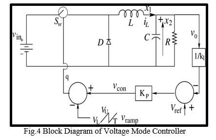
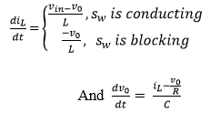
The voltage mode controlled BUCK -BOOST converter circuit is shown in fig. 4. It consists of a controlled switch Sw (MOSFET), an uncontrolled switch diode D (diode), an inductor L, a capacitor C, and a load resistance R. The circuit shown in fig. 4 is a non-smooth dynamical system described by two sets of differential equations:
The switch is controlled by analog PWM feedback logic. This is achieved by obtaining a control voltage vcon as function of the output capacitor voltage vC and a reference signal Vref in the form,
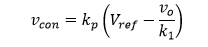
Where, kp is the gain of proportional controller and k1 is the factor of reduction of the output voltage v0. An externally generated saw-tooth voltage defined as vramp (t) is used to determine the switching instants.
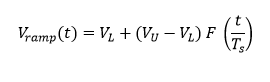
Where TS is the time period and VU and VL are upper and lower threshold voltages respectively. Here F (x) denotes the fractional part of x: F (x) = x mod 1. In voltage mode control, the controlled voltage vcon is then compared with the periodic saw-tooth wave Vramp, to generate the switching signal q is described by
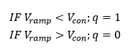
The inductor current increases while the switch Sw is on i.e q=1 and falls while the switch S is off i.e. q=0.
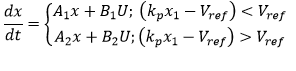
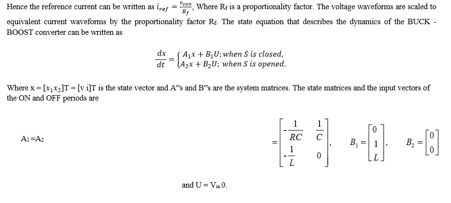
If the current reaches zero value before the next clock cycle, the operation is said to be in DCM, else it is in CCM. The state equation that describes the dynamics of the BUCK -BOOST converter can be written as
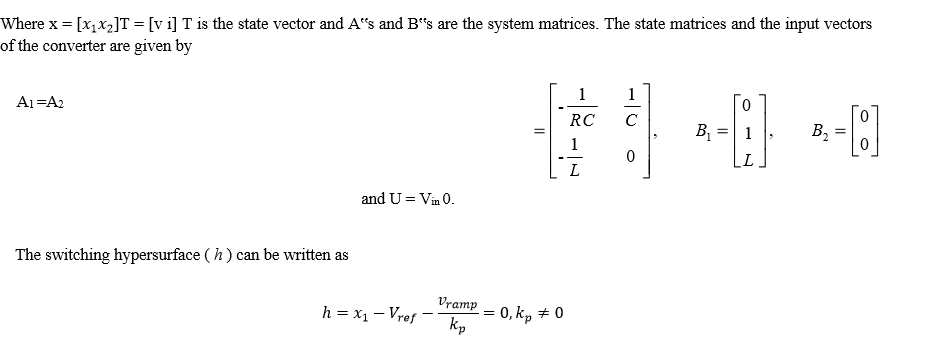
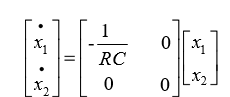
For discontinuous conduction mode, inductor current reaches zero before the next clock cycle. In this case, the state equation of the converter can be written as
However, VMC have a few disadvantages. Any change in input voltage will alter the gain and influence the system dynamics behavior. VMC cannot correct any disturbance immediately until it is detected at the output since the disturbances are delayed in phase by the inductor and capacitor prior to the output.
2. Current- mode Controlled BUCK - BOOST Converter: Another control scheme that is widely used for ac-ac converters is current mode control. Current-mode controlled ac-ac converters usually have two feedback loops: a current feedback loop and a voltage feedback loop. The inductor current is used as a feedback state.
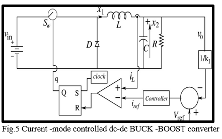
A current mode controlled dc-dc BUCK -BOOST converter circuit is shown in fig. 5. At the beginning of a switching cycle, the clock signal sets the flip-flop (q=1), turning on the (MOSFET) switch. The switch current, which is equal to the inductor current during this interval, increases linearly. The inductor current iL is compared with the control signal iref from the controller. When iL, is slightly greater than iref, the output of the comparator goes high and resets the flip-flop (q=0), thereby turning off the switch. The switch will be turned on again by the next clock signal and the same process repeated.
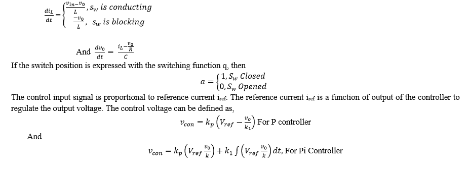
The BUCK -BOOST converter circuit operates at continuous conduction mode. Depending on the state of the switch, there are two circuit configurations, which are described by the following differential equations:
III. VARIABLE SWITCHING FREQUENCY HYSTERETIC CONTROLLERS
In this section, the basic ideas about the hysteretic controlled converters with variable switching frequency are described. As shown in Fig. 6, the voltage hysteretic controller regulates the output voltage ripple within the hysteretic band. Similarly, a current hysteretic controller directly regulates the inductor current of the converter by regulating the inductor ripple or a scaled version of it within the hysteretic band.
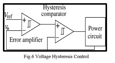
A. Hysteretic Voltage-Mode Controller
Hysteretic voltage-mode control is the simplest control method available. The concept of operation is very simple. The switch is turned on, when the output voltage falls below minimum set point (i.e., lower boundary) and turns off when output voltage is higher than maximum set point (i.e., upper boundary). Since the controller does not use a compensation network, the converter is able to react quickly to a transient event making it seem like a perfect solution for voltage regulator modules. However, the drawback of the voltage-mode hysteretic controller is its reliance on the converters output capacitor parasitic. A block diagram of voltage hysteretic controlled converter is illustrated in Fig 6.
B. Hysteretic Current-Mode Controller
Hysteretic current-mode control functions by controlling both the peak inductor current and the valley inductor current. It does not require an external oscillator or saw- tooth generator for operation and it has the ability to provide a fast response to a transient event. Fig. 7 illustrates a block diagram of a current-mode hysteretic controlled dc-dc converter.
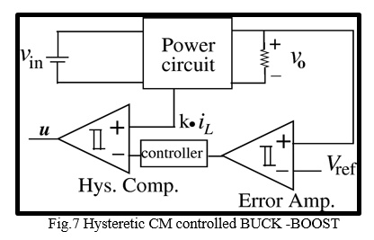
Converter The power converter circuit with feedback control generally consists of:
- A power stage with switches Sw and D, and storage elements L and C,
- An inner controller preserving the converter’s working principle by switching the circuit topology,
- An outer controller adjusting the inner loop’s reference in response to deviations from the desired output.
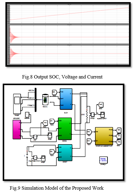
IV. SIMULATION RESULT
Description this plot indicates the state of charge of the PV with respect to current and voltage as the SOC increases and becomes stable the voltage value also becomes stable
Conclusion
Study of the PWM voltage mode manages, PWM present day mode manages and their operation has been given. The blessings and disadvantages of each manipulate technique whilst applied in switched-mode power converters are proven. The evaluation and the theories of SM manage had been given in details. SM control implemented in dc-dc BUCK -BOOST converter is offered. Then a comparative evaluation on conventional PWM controllers and SM control has been performed. The simulated end result showed the pleasurable theories of SM control. The blessings of SM manage over other control methods are described. The primary idea of operation of tristate greenback converter has been studied. The implementation of fixed frequency hysteretic modern control to the tristate greenback converter has been given. The output voltage, main inductor contemporary waveforms had been studied in constant-nation vicinity and in dynamic place
References
[1] Eltaib Abdeen, Mahmoud A. Gaafar, Mohamed Orabi, Masahito Shoyama, \"Three Level T-Type Buck-Boost Voltage Source Inverter\", Power Electronics and Renewable Energy (CPERE) 2019 IEEE Conference on, pp. 175-180, 2019. [2] Fahad Alsokhiry, Ibrahim Abdelsalam, Grain Philip Adam, Yusuf Al-Turki, \"High-power medium-voltage three-phase ac–dc buck–boost converter for wind energy conversion systems\", Electric Power Systems Research, vol. 177, pp. 106012, 2019. [3] M. Haider, D. Bortis, J. W. Kolar, Y. Ono, \"Novel Single-Phase Buck+Boost PFC Rectifier with Integrated Series Power Pulsation Buffer\", Power Electronics and ECCE Asia (ICPE 2019 - ECCE Asia) 2019 10th International Conference on, pp. 1-10, 2019. [4] Ahmed Abdullah Hossam-Eldin ; Ahmed Kadry Abdelsalam ; Abdelrahman Mohamed Farghly Enhanced Performance Four-Switch Three-Phase Buck-Boost Based Inverter IEEE 2018 [5] David Menzi ; Dominik Bortis ; Johann W. Kolar A New Bidirectional Three-Phase Phase-Modular Boost-Buck AC/DC Converter IEEE International Power Electronics and Application Conference and Exposition (PEAC) 2018 [6] D. Elizondo and A. Urtasun, \"Dual-mode soft-transition control for single-phase grid-connected photovoltaic inverters\", Proc. of the 19th IEEE Workshop on Control and Modeling for Power Electronics (COMPEL), Jun. 2018. [7] R. Hasan, S. Mekhilef, M. Seyedmahmoudian and B. Horan, \"Grid-connected isolated PV microinverters: A review\", Renew. Sustain. Energy Rev., vol. 67, pp. 1065-1080, Jan. 2017. [8] Ayan Mallik, Alireza Khaligh, \"An Integrated Control Strategy for a Fast Start-Up and Wide Range Input Frequency Operation of a Three-Phase Boost-Type PFC Converter for More Electric Aircraft\", Vehicular Technology IEEE Transactions on, vol. 66, no. 12, pp. 10841-10852, 2017. [9] S. S. Lee and Y. E. Heng, \"Improved Single-Phase Split-Source Inverter with Hybrid Quasi-Sinusoidal and Constant PWM\", IEEE Trans. Ind. Electron, vol. 64, no. 3, pp. 2024-2031, Mar. 2017. [10] Ayan Mallik, Bryan Faulkner, Alireza Khaligh, \"Control of a single-stage three-phase boost power factor correction rectifier\", Applied Power Electronics Conference and Exposition (APEC) 2016 IEEE, pp. 54-59, 2016. [11] A. Abdelhakim, P. Mattavelli and G. Spiazzi, \"Three-Phase Split-Source Inverter (SSI): Analysis and Modulation\", IEEE Trans. Power Electron, vol. 31, no. 11, pp. 7451-7461, Nov. 2016. [12] Ahmed Darwish, Ahmed M. Massoud, Derrick Holliday, Shehab Ahmed, B. W. Williams, \"Single-Stage Three-Phase Differential-Mode Buck-Boost Inverters With Continuous Input Current for PV Applications\", Power Electronics IEEE Transactions on, vol. 31, no. 12, pp. 8218-8236, 2016. [13] M. K. Nguyen, Y. C. Lim and S. J. Park, \"A comparison between single-phase quasi-Z-source and quasi-switched boost inverters\", IEEE Trans. Ind. Electron., vol. 62, no. 10, pp. 6336-6344, 2015 [14] D. Sun, B. Ge, X. Yan, D. Bi, H.Y. Zhang Liu, H. Abu, et al., \"Modeling impedance-design and efficiency analysis of quasi-Z source module in cascaded multilevel photovoltaic power system\", IEEE Trans. Ind. Election., vol. 61, no. 11, pp. 6108-6117, 2014. [15] R. Burkart and J. W. Kolar, \"Component cost models for multi- objective optimizations of switched-mode power converters\", Proc. of the IEEE Energy Conversion Congress and Exposition (ECCE), pp. 2139-2146, Sept. 2013Transactions on Industrial Electronics, 64(11):8855–8866, Nov 2017.
Copyright
Copyright © 2022 Mr. Ashish Nagrale, Prof. Pooja Sahastrabudhe. This is an open access article distributed under the Creative Commons Attribution License, which permits unrestricted use, distribution, and reproduction in any medium, provided the original work is properly cited.

Download Paper
Paper Id : IJRASET40087
Publish Date : 2022-01-26
ISSN : 2321-9653
Publisher Name : IJRASET
DOI Link : Click Here
 Submit Paper Online