

Ijraset Journal For Research in Applied Science and Engineering Technology
Study of RCC Silo structure for different Height/Dia. ratio
Authors: Avinash Nighute, Dr. V. R. Rathi
DOI Link: https://doi.org/10.22214/ijraset.2022.45305
Certificate: View Certificate
Abstract
This work shows the effect of height to diameter ratio on reinforced cement concrete circular silo. Janssen’s theory as per IS 4995:1974 part I & part II is used to determine the load intensity and structural dimensions. The Response Spectrum Method along with Wind load Analysis is used for analysis of the reinforced cement concrete silo structures. In the present studies, the silo structures are considered to be in Zone V of IS 1893:2005 Part 3 and IS 875:2015 Part IV. SAP 2000 software is used for the modelling and analysis of silo structure. Two different heights to diameter ratios are used for getting results on four models in the form of horizontal pressure on the silo wall due to stored material, displacement and base shear. The displacement will be more at the top of the structure due to increase in height of the silo. For earthquake and wind load analysis, empty silo structure shows the maximum value of displacement and base shear.
Introduction
I. INTRODUCTION
Silos are basically Storage structures (example - bins) and bunkers for storing different types of materials. Depending upon the plane of the rupture, silo and bunkers are classified. If the plane of rupture of the bin intersects the top surface of the bin, then it is called a bunker. If the plane of rupture of the bin intersects the opposite side of the bin, then it is called a silo. In silos, the height is greater than the diameter. Height/Diameter ratio greater than or equal to two for the reduction of lateral pressure over the large height takes place as per the IS code 4995(Part I):1974. Generally, the shape of the silo is circular, but it may change to square, rectangular or polygonal shape as per requirement. Silo is provided with roof and bottom share is kept conical, pyramidal or flat. Silos are supported with a number of columns, total structure wall, hopper top and column is connected by the ring beam to distribute the load. Silo design is used for both vertical and horizontal pressure. The exact pressure calculation is difficult due to many variables which act during the emptying and filling of material.
During the structural design of the silo, various loads are simulated according to its intended use, structure type, size, design lifetime, material, location, environment in order to assure life safety and to assure essential functions. For structural design, the self-weight of structure should be considered, live load on the top of roof also needs to be considered, snow load needs to be taken into consideration as per location, wind load as per revised IS: 875 (Part III):2015 code cyclonic factor needs to be considered. Seismic load is a basic requirement in every structural design due to the larger mass concentrated above the slender portion and stored material load acted in horizontal, vertical direction. The frictional pressure should also be considered. Effect of vertical seismic loads is small as compared to horizontal seismic loads on the tall silos. Seismic load magnitude in horizontal direction is directly related to the weight of silo.
In the past, researchers worked on study of silo structures considering the effect of earthquakes like Durmu & Ramazan (2015) as material pressure increases as slenderness ratio increases. This results in decreasing silo stiffness. Christoph Butenway, Julia Rosin & Stefan Holler (2017) did nonlinear time history analysis. Their study showed more Static equivalent loads to a slender. Arun L &Mamatha K.K (2018) study showed base shear increases up to 30% to 40% due to the material densities, stored material and its densities are directly proportional to the state of stress in the cylindrical portion. Rajni S Togarsi (2015) study showed silo supported on shear wall experiences less lateral displacement than silo supported on columns. Amiya K. Samanta, DeshBandhu Mukherjee, Prasanta Patra (2013) study indicates that the values of hoop stress are critical in windward side. Varun G., Kavan M.R. (2017) study shows the maximum displacement of the silo structure is at the empty condition of silo structure.
II. METHODOLOGY
The aim of study is to verify the behavior of the circular reinforced concrete silo structure under various loading and conditions. Find out the Response of reinforced concrete silo structure using response spectrum method and wind analysis in terms of lateral displacement and Base Shear.
A. Structure data
Silo Type – Circular Silo of RCC.
Material stored in structure – Wheat (Assumed)
Bulk Density – 8.5 kN/m2 (Table 1, IS: 4995 (part I): 1974)
Angle of internal friction (Ø’) – 280 (Table 1, IS: 4995 (part I): 1974
H/D ratio – 4.44&3.33
Diameter – 6m &4.5m
Cylindrical portion height – 26.5m, 15 m, 20m
Silo hooper height – 2.5m
Hooper bottom opening – 1m
Column height above plinth – 5m
Column height below plinth – 1m
|
H/D |
3.33 |
|||
|
H(m) x D(m) |
15 x 4.5 |
20 x 6 |
||
|
Stage |
Full |
Empty |
Full |
Empty |
|
Angle of wall friction (δ) |
21 |
16.8 |
21 |
16.8 |
|
Coefficient of wall friction (µ) |
0.383 |
0.301 |
0.383 |
0.301 |
|
Pressure Ratio (λ) |
0.5 |
1 |
0.5 |
1 |
|
R = D/4 |
1.125 |
1.5 |
||
TABLE I
Various silo structure wall parameter
|
H/D |
4.44 |
|||
|
H(m) x D(m) |
20 x 4.5 |
26.5 x 6 |
||
|
Stage |
Fill |
Empty |
Fill |
Empty |
|
Angle of wall friction (δ) |
21 |
16.8 |
21 |
16.8 |
|
Coefficient of wall friction (µ) |
0.383 |
0.301 |
0.383 |
0.301 |
|
Pressure Ratio (λ) |
0.5 |
1 |
0.5 |
1 |
|
R = D/4 |
1.125 |
1.5 |
||
A. Modelling and analysis Layout
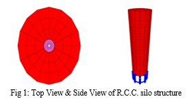
SAP 2000 software is used for modelling with the dimension taken under consideration. Six columns consist of model with fixed support, shell and Beam. Following figure 1 shows a 3D view in SAP2000.
B. Section property
TABLE II
Structural member sizes for R.C.C. silo structure model
|
Sr. No. |
Member |
Circular Silo |
|||
|
H/D = 3.33 |
H/D = 4.44 |
||||
|
1 |
Height |
15 m |
20 m |
20 m |
26.5 m |
|
2 |
Diameter |
4.5 m |
6 m |
4.5 m |
6 m |
|
3 |
Wall Thickness |
150 mm |
150 mm |
150 mm |
150 mm |
|
4 |
Column |
550 x 550 mm |
550 x 550 mm |
550 x 550 mm |
550 x 550 mm |
|
5 |
Ring Beam |
300 x 300 mm |
300 x 300 mm |
300 x 300 mm |
300 x 300 mm |
C. Load Intensity
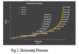
Static load and dynamic loads generally structure is having.Mentioned loads are majorly affected the structure in earthquake. IS 4995:( Part I) 1974 is used for load calculation of the silo wall. General Requirement and Assessment of bin Load should be used. Janssen’s theory is used for the calculation of Vertical pressure on the horizontal cross section of the stored material and the horizontal pressure on silo walls due to stored material. The various loads on part of silo structure are as follows
- Horizontal pressure on Silo walls due to stored material. (Ph)
2. Wall load due to granular material
TABLE III
Wall load
|
H (m) x D (m) |
15 x 4.5 |
20 x 6 |
20 x 4.5 |
|
26.5 x 6 |
|
Vertical pressure on the horizontal cross section of the stored material. (kN/m2) |
48.971 |
66.57 |
48.971 |
|
66.57
|
3. Self weight of all members.
III. Method of analysis
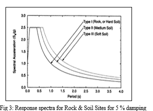
All IS 1893 (Part IV): 2005 Criteria for earthquake resistant design of structures. stack-like structures are used for industrial purpose. for earthquake analysis of silo structureIndian standard is used. insuch a caseDynamic response spectrum modal analysis will be necessary; it is a dynamic analysis method. It is done using the design spectrum (specified in 8.2 section or a site-specific design spectrum). In this method, peak response of structure during seismic action is obtained directly from the design response spectrum, which in turn is used for structural design purposes. The following figure shows the response spectra for different soil conditions. Figure 3 Response spectra for Rock & Soil Sites for 5 % damping
Zone – V
Z = 0.36
Soil Type – Medium soil
Importance factor – 1.5
Response reduction factor – 3
Damping – 5%
For wind load analysis IS 875 (Part III):2015 Design loads (Other than Earthquake) for building and structures be used the following wind load parameter are consider for analysis
Wind speed (Vb) - 50 m/s.
Terrain category – 1
Terrain category = 1
Probability factor K1 = 0.9
Topography factor K3 = 1
Terrain roughness and height factor K2 = Change as per height.
Cyclonic factor K4 = 0
IV. Result and Discussion
A. 15m – 4.5m
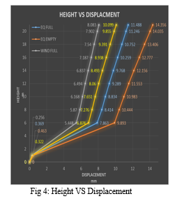
Figure 4 shows the displacement of the cylindrical portion verses height of cylindrical portion of structure for a wind loading and earthquake loading at full load in silo due to empty silo and with astore material in silo. When we consider only EQ loading of empty silo, it shows maximum 14.365mm displacement at the top of silo structure comparing full load. If we are comparing result of displacement with wind loading and EQ loading, then we found the silo structure show maximum displacement at EQ loading
B. 20m – 6m
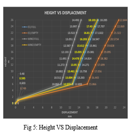
This figure5 shown the displacement of the cylindrical portion verses height of cylindrical portion of structure for a wind loading and earthquake loading at full load in silo due to empty silo and with a store material in silo. When we consider only EQ loading of empty silo, it shows maximum 22.844 mm displacement at the top of silo structure comparing full load. If we are comparing result of displacement with wind loading and EQ loading, then we found the silo structure show maximum displacement at EQ loading
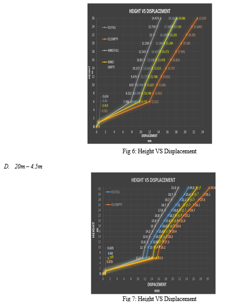
C. 20m – 4.5m
This figure 6 showed the displacement of the cylindrical portion verses height of cylindrical portion of structure for a wind loading and earthquake loading at full load in silo due to empty silo and with a store material in silo. When we consider only EQ loading of empty silo, it shows maximum 22.819 mm displacement at the top of silo structure comparing full load. If we are comparing result of displacement with wind loading and EQ loading, then we found the silo structure show maximum displacement at EQ loading
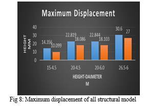
This figure 7shown the displacement of the cylindrical portion verses height of cylindrical portion of structure for a wind loading and earthquake loading at full load in silo due to empty silo and with a store material in silo. When we consider only EQ loading of empty silo, it shows maximum 30.60 mm displacement at the top of silo structure comparing full load. If we are comparing result of displacement with wind loading and EQ loading, then we found the silo structure show maximum displacement at EQ loading.
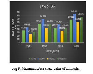
E. Maximum Displacement
All four modelled displacement consider, whose depth to height ratio is more these model shows maximum displacement is not correct is totally depends on the silo structure.
The model 20m height and 6 m diameter and 20m height and 4.5m diameter has different H/D ratios but it shows nearly the same value of the maximum displacement. I the figure 4.4 whose height is more as compare to other shows the maximum value of displacement i.e. 26.5m height of the silo.
F. Base shear
In all the model EQ loading condition at empty stage condition shows the maximum value of the base shear i.e 846.983 kN As the diameter increases the base shear value also increases.
If we consider the height of the structure, these are also affecting the value of the base shear. As the height increases, the value of base shear increases. The base shear depends on the height and diameter of the silo.
Conclusion
1) Silo structure wall having Horizontal pressure due to stored material, increases as the diameter increases and after a 1/1.25 times height of structure the value goes nearly constant as height increases. 2) The height of silo structure increases due to the displacement will be more at top of structure boz more mass attract more seismic energy. 3) In Earthquake and wind load analysis of structure show maximum displacement value in empty condition.”
References
[1] Togarsi,R. (2015). “Seismic response of reinforced concrete silos” International Journal of Research in Engineering and Technology,4(9) [2] Varun, G., and Kavan, M.R. (2017). “Study of Behavior of RC Silo for LateralLoads Using Sap” International Journal for Research in Applied Science &EngineeringTechnology,(5)9, 1177-1182 [3] LydiaMatiaskova(2018)“Failureanalysisofreinforcedconcretewallsofcylindricalsilosunderelevatedtemperatures”DepartmentofConcreteStructures and Bridges [4] C.Bywalski (2019)”Acasestudyofthecollapseoftheover-chamberreinforced concrete ceiling of a meal silo’’ Wroc?aw University of Science and Technology,Wroc?aw, Poland. [5] Quan Chen(2021) a, R. Li “Measurement of granular temperature and velocity profile of granularflowinsilos’’SchoolofEngineering,NewcastleUniversity,UK [6] Rafa? Koby?ka(2020) “DEM simulation of the pressure distribution and flow pattern in a model grain silo with an annular segment attached to the wall’’ Institute of Agrophysics, Polish Academy of Sciences, [7] Arash Raeesi (2014) “Failure analysis of steel silos subject to wind load’’ Department of Civil and Environmental Engineering
Copyright
Copyright © 2022 Avinash Nighute, Dr. V. R. Rathi. This is an open access article distributed under the Creative Commons Attribution License, which permits unrestricted use, distribution, and reproduction in any medium, provided the original work is properly cited.

Download Paper
Paper Id : IJRASET45305
Publish Date : 2022-07-04
ISSN : 2321-9653
Publisher Name : IJRASET
DOI Link : Click Here
 Submit Paper Online