

Ijraset Journal For Research in Applied Science and Engineering Technology
Study of Various Network Topologies Using Graph Theory
Authors: Manish Kapruwan, Priyavrat Pandey, Suraj Kunjwal, Varsha Gautam
DOI Link: https://doi.org/10.22214/ijraset.2022.45229
Certificate: View Certificate
Abstract
Network Topology is an optimized design or an arrangement of the network including its nodes and the connecting lines. Being an arrangement of various components of network it helps us in defining the layout of structure of network like communication with another node or point effortlessly. It presents not only physical framework but also logical connections too. With the understanding of physical topology, we can easily get to know that where do we have to install the cable and nodes, whereas logical topology explains the flow of data and its transmission. Keeping this in view, a review has been done about various network topologies. In this work, network connectivity has been discussed with the help of graph theory and advantages, disadvantages of various network topologies are also explained.
Introduction
I. INTRODUCTION
A network is a system that allows two or more computers (also known as nodes) to communicate with one another. These computers, also known as participating nodes, actively participate in the communication process, and topology is merely the configuration of how these nodes will interact [1,2]. It is a topology that controls how data flows between nodes [10]. As a result, the structure and arrangement of components in a computer communication system is known as network topology. As a result, it is a configuration of two or more nodes talking with one another, usually over the internet via a specific media. It facilitates communication among these nodes. Each node must be connected to other nodes using the appropriate sort of topology for a network to function properly. The sort of topology used has a big impact on how well devices are used. It is critical to choose the right type of topology to adopt in order for the network to function properly with proper message transmission and reception. To gain a better understanding of a network and how communication occurs, it is critical to grasp and comprehend the underpinning topology on which the entire network is built. Its appropriate implementation considerably enhances the network's performance. A better performing topology aids in progressively increasing the speed with which a message is carried over the network [3,4]. A better-performing topology aids in improving the rate at which a message is transmitted throughout the network. Better network, the shorten the communication delay. On many levels, making the right decision about the sort of topology to use is advantageous. First and foremost, it lowers implementation costs right from the start. Even in the long run, it saves a lot of money on operations and maintenance. The decision to select a decent topology proves to be advantageous in every way. Even yet, diagnosing or locating a flaw in the topology is simple. A solid implementation of this topology will also aid in the efficient use of all network resources. The cost of operations will be reduced automatically if resources are properly utilized.
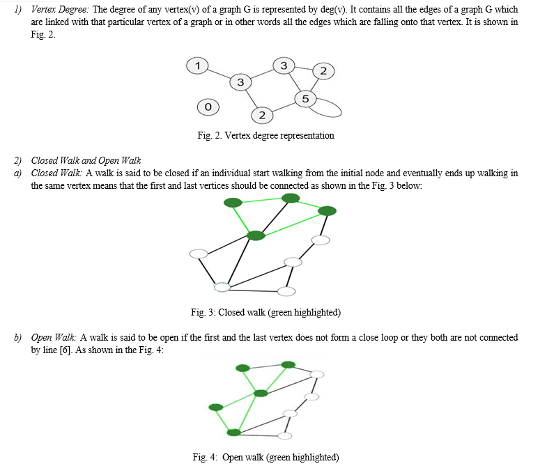
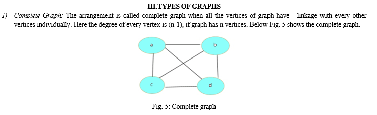
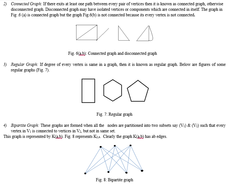
II. GRAPHS & IT’S SOME TERMINOLOGIES
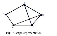
Graphs have several meanings whether representing data in chart format or representing data etc. Graphs in topology is a mathematical representation of networks formed of edges and nodes. However, it is not important that how long lines are and where are the points/nodes are localized. Graphs consists of two things:
- V (G) is a collection of all elements which are like points, vertices of graph.
E(G) is a collection of all non- ordered pair of unique nodes called edges of graph and these are represented like G(V, E)[6]
IV. CONNECTIVITY & IT’S VARIOUS ATTRIBUTES
Connectivity is the one of the most basic and fundamental concepts in graph theory. A graph can be rendered of either connected or disconnected in terms of topological network. In graph theory we must have at least one path by which we connect one point in graph to another point of the same given graph, then those graphs are called as connected graph otherwise it is called as disconnected graph.
Adherence of the graph can be measured through graph connectivity as a network.
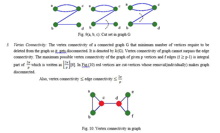
- Cut Set: In a given connected graph G, a cut set is collection of those edges whose deletion from the given graph makes disconnected or in other words if removal of certain number of edges leaves it disconnected then those removal edges are considered as cut set of the graph [6]. A cut set always cuts a graph in two pieces and reduces the rank of graph.
Some underlying properties of cut sets
- There must be at least one branch of every spanning tree contained by every cut set in connected graph G.
- A cut set always contains at least one branch of every spanning tree of G with any with minimal set of edge.
2. Edge Connectivity: The least number of edges whose deletion makes connected graph G disconnected. which is symbolised by λ(G). Therefore, if λ(G) ≥ k, then the graph G will be called k-edge-connected [6]. Degree of a vertex with minimal degree in G cannot be surpassed by the edge connectivity of graph G. The graph G shown in Fig. 9(a,b,c) can be split up into two components by removing any one of the edges bc or bd, therefore edges bc or bd are bridges.
V. CLASSIFICATION OF NETWORKS ON THE BASIS OF NETWORK TOPOLOGIES
- Bus Topology: This physical configuration consists of many (hosts) that linked to a bus as shown in Fig. 11, which acts like a backbone of this whole topology. In this topology whenever the communication has to be happened between the computers (hosts) or nodes, the message gets broadcasted in the whole network, but only the desired recipient gets or digests the message [7].
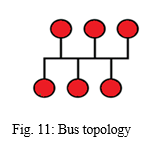
Ease of instalment is not much higher as we require less numbers of cable to link all computer/nodes/hosts together. Failure of any computer/node/host does not impact the functioning of rest nodes. Being the simplest network topology, it sounds fit for temporary networks. It can be extended further easily by simply joining the node to mainstream. Although this topology has its own disadvantages as network gets slow or disrupt if we keep on the adding more nodes on the mainstream. Even small fault in the topology backbone can stops all the transmission process.
2. Star Topology: This configuration has a centre hub/top level node or a switch serves as the backbone of the whole system, where all the nodes/computers/hosts are connected. Since in this topology no two other nodes are directly linked with each other which does not results the direct traffic come in between the network. Messages sent by the one node is get received by the hub first which later can broadcast all the message to all or if the hub is of good quality then it will be directly sent to the recipient (Fig. 12).
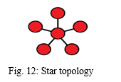
Failure between in the central node and other nodes does not affect the network. It gets easy to diagnose the fault. Again, the network is scalable so can add multiple nodes to the central node. It gives you good performance. This configuration turns out to be expensive, when it comes to scalability (as we need more cabling then). Another concern for this configuration is the limited number of central hubs. Too much cabling can put an immense pressure at the central node.
3. Ring Topology: This configuration has node which are surely connected with two other nodes or in terms of graph we can say that each node has degree 2 Fig. 13. This configuration forms the P2P (point-to-point) linkage between the two other nodes [9,11]. Message sent in this topology from one node to another node travel from source to sink by the intermediate nodes. In ring topology messages are sent in two ways like unidirectional and bi-directional (sending message from the both two cables).
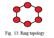
In this topology extra work stations can be added further without affecting the performance of network. It is easy to install and expand. Data is transferred at a very high speed in this configuration (small networks). It is easy to manage. If in case any of the nodes gets shut down, then it affects the whole network. In case to communicate over this network all of the nodes have to be open. It is expensive and transmission time between two nodes is bit long.
4. Mesh Topology: This topology has the point-to-point connections among rest of the nodes. Being connected to every possible node out there in the network, message from source node to destination node can be received through many paths. This combination of nodes reduces the chance of failure of single point failure with Mesh topology as in Fig 14.
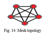
Having multiple paths for the data to be received, the data transmission gets fast [8,9,11,13]. Faults can be diagnosed easily. Source node finds the best route for sending the data to the receiver ends Cost of establishing these kinds of networks are high. Another turn off, of this network is to have routing algorithm computation for each node. Suitable for small network otherwise this network can incur heavy cost.
5. Tree Toplology: Bus topology and star topology traits are combined in tree topology. It is a form of organization in which each computer is linked to every other computer in a hierarchical manner. In a tree topology, the top node is referred to as the root node, and all subsequent nodes are its offspring. Every star is linked to bus. For the data transmission between two nodes, only one path is available [11,13]. As a result, a parent-child hierarchy is formed. Fig. 15 represents tree topology.
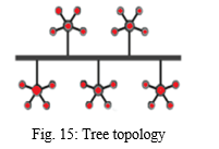
Broadband transmission, or the ability to send signals across great distances without attenuation, is the principal use of tree topology. The new device can be integrated into the current network. Consequently, we can assert that tree topology is amenable to expansion. The whole network in a tree topology is separated into manageable portions known as star networks, making it easier to administer and maintain. In a tree topology, error identification and rectification are fairly simple. The network as a whole is not impacted by the malfunction in one station. For each segment, there is point-to-point wiring.
It gets challenging to solve the issue if the node develops any faults. Broadband transmission requires a lot of expensive equipment. The main bus cable is the key component on which a tree topology depends, and its failure will harm the entire network. It gets challenging to modify when new devices are introduced.
6. Hybrid Topology: A hybrid network is developed based on the needs of the enterprise. By making the most of the available resources and in accordance with the needs of the organisation, the hybrid network can be developed [12]. Mesh topology, bus topology, and ring topology are a few examples of network topologies that can be combined to create a hybrid topology. Its installations and requirements, such as the performance of desired network, the number of computers, and their location, influence its usage and selection. Fig. 16 shows the hybrid topology structure, which combines several topologies.
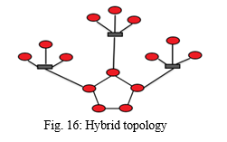
However, it offers a complex structure and a range of technologies are required for its practical execution [14]. Additionally, it has the benefit of increased flexibility; it can improve fault tolerance and makes it simple to add or remove different fundamental topologies. This topology ignores the weaknesses of the various connected topologies and only the advantages of selected topologies are considered. A hybrid network is a network that has been built in such a way that it can easily integrate new hardware elements, such as additional concentration points. With the most recent inclusion of additional pieces, it is quite simple to increase the network size without disrupting the existing architecture. Flexibility is one of the main advantages of hybrid topology. Along with many other advantages, they provide high-end equipment, signal strength, throughput, and data communication. It has the capacity to transport data quickly between several networks.
But topology has its disadvantages too. As the many topologies are linked in the hybrid topology, managing the topology becomes difficult. Making this kind of architecture is not a simple task for designers. The installation and configuration process require a high level of efficiency. In comparison to other topologies, the hybrid topology is significantly more expensive to purchase and maintain. In this network structure, hubs are also necessary and expensive to connect two distinct networks. Due to the hybrid topology's typically larger-scale structures, it may also require sophisticated network equipment, numerous connections, and other things. Another drawback of hybrid topology is that, despite its ease of fault detection, it requires a multi-station network.
VI. NETWORK TOPOLOGIES ANALYSIS REPORT
In TABLE 1 various topologies information transmission, setup, expansion, troubleshooting, cost and cabling concerns are compared.
|
Topology |
Information Transfer |
Setup |
Expansion |
Troubleshooting |
Cost |
|
Bus Topology
|
One computer at a time sends information. Information goes along the cable and the computer accesess the info. |
Connect the cable from one computer to another and so on. |
To add computer one must shut down the network and disconnects the cable from existing network |
If one computer fails then the entire network gets down. |
Cheaper network as only one cable is used. |
|
Star Topolgy |
All information passes through the central network connection. |
Each computer must be close to central hub. Wire should be of maximum 100m length. |
Add a new computer by plugging in a new cable from the computer to the connection device. |
When one computer goes down then the rest network doesn't affected. |
It requires costly connection devices. |
|
Ring Topology |
Information goes in one direction around the ring and passes along the ring until it reaches the sink computer. |
Computers are close to each others. Setup is easy. |
Cable between the computers must be broken to add a new computer |
If there is a break in the cable or an error in the network, information continues to transfer through rest of the ring until reaching the point of break. |
Expensive topology due to cable intensive. |
|
Mesh Topology |
Often used across long distances. |
Often created when expanding an existing network. |
Connection devices make combining different topology is easy. |
Troubleshooting is difficult in this topology because of the variety of technologies. |
Expensive, large and usually complicated. |
|
Tree Topology |
Send signals across great distances without attenuation. |
Bus topology and star topology traits are combined in tree topology |
The new device can be easily integrated into the current network. |
The main bus cable is the key component on which a tree topology depends, and its failure will harm the entire network. It gets challenging to modify when new devices are introduced. |
Broadband transmission requires a lot of expensive equipment. |
|
Hybrid Topology |
It has the capacity to transport data quickly between several networks. |
As per requirement and needs of the organisation, the hybrid network can be developed. |
It has the great benefit of increased flexibility. |
It is easy to detect faults. |
It is significantly more expensive to purchase and maintain. |
Table1: Comparison Of Different Topologies
VII. FUTURE SCOPE OF THE PROJECT
Presently the review presented here is intended to focus and analyse basic network topologies but in future, we wish to work on various hybrid topologies, clustering topologies like dragonfly, dragonfly+, and many more.
Conclusion
We have reviewed network and various network connectivity components using graph theory in this work. We have conducted an analytical analysis of various basic topologies in this report, which provides us with a quick overview of each topology and its characteristics. We have described above that each topology has its own set of benefits and drawbacks. Various topologies information transmission, setup, expansion, troubleshooting, and cost are also compared.
References
[1] Rumanov, Aleksandr Yu.,(2019), Development of routing algorithms in network in network on chip based on ring circulant topologies, Heliyon, Volume 5, Issue 4, e01516, ISSN 2405-8440, https//doi.org/10.1016/j [2] Gupta, A.K. and Daily, W.J.(2006),Topology optimization of interconnection networks, IEEE Computer Architecture Letters,5(1). [3] Newman, M. Networks (Oxford uni. Press, Oxford, 2018). [4] Barabási, A-L Networks Science (Cambridge Uni. Press, Cambridge, 2016). [5] Schaum Outlines: Graph Theory,V.K.Balakrishnan [6] Deo, Narsingh: Graph Theory With Applications To Engineering And Computer Science ,Prentice -Hall,INC. [7] Pandya, Kartik(July 2013), “Network Structure or Topology”, International journal of Advance Research in Computer Science and Management Studies/ volume 1, Issue 2. [8] Santra, Santanu, Acharjya, Pinaki Pratim (January 2013), “A Study and Analysis on Computer Network Topology for Data Communication”, International Journal of Emerging Technology and Advanced Engineering/ volume 3, Issue 1. [9] Bisht, Nivedita and Singh Sapna(March 2015), Analytical Study of Different Network Topologies , International Research Journal of Engineering And Technology, Volume :02 Issue : 01. [10] Matthias Wählisch(2010), Modeling the Network Topology, In: Modeling and Tools for Network Simulation, (Klaus Wehrle, Mesut Günes, James Gross Ed.), pp. 471--486, Heidelberg: Springer. [11] Uysal,Omer, Misirli ,Zeynel Abidin(2009), Physical topologies in computer networks, Recent Advances in Applied Mathematics and Computational and Information Sciences,Volume-II,377-381. [12] Aristarkus ,Datukun Kalamba, Palaniappan, Sellappan & Purnshatman,Tatchanaamoorti(2017), Hybrid Topology Design for Improving Network Performance, Global Journal of Computer Science and Technology: E Network, Web & Security Type: Double Blind Peer Reviewed International Research Journal Publisher: Global Journals Inc. (USA) Online ISSN: 0975-4172 & Print ISSN: 0975-4350, Volume 17 Issue 3 Version 1.0. [13] Lim, Francis Pol(2016), A Review-Analysis of Network Topologies for Micro enterprises, Advanced Science and Technology Letters Vol.135 (CES-CUBE 2016), pp.175-180http://dx.doi.org/10.14257/astl.2016.135.42. [14] Dehmamy, N., Milanlouei, S. & Barabási, AL. A structural transition in physical networks. Nature 563, 676–680 (2018). https://doi.org/10.1038/s41586-018-0726-6 [15] Hai,Zheng Hai and Guoqing, Zhang(2002), \"Research on physical network topology discovery algorithm [J]\", computer research and development, no. 03, pp. 264-268. [16] Mingbing, Tang(2016), Design and implementation of network management system based on SNMP., Jilin University. [17] Aristarkus ,Datukun, Kalamba, Palaniappan, Sellappan & Purnshatman, Tatchanaamoorti (2016). Towards proposing network topology for improving performance in Plateau State University Bokkos. International Journal of Computer Networks and Communications Security (IJCNCS). 4( 9). 259- 264.http://www.ijcncs.org/published/volume4/issue 9/index.php [18] Liu,Yunhuai, Zhang, Qian , and Lionel M. Ni(2010), “Opportunity Based Topology Control in Wireless Sensor Network” IEEE Transactions on parallel and distributed systems, VOL.21, NO. 3, http://dx.doi.org/10.1109/TPDS.2009.57 [19] John Peter and Timo Perttunen (2014)( Sterlite) : Network Topologies
Copyright
Copyright © 2022 Manish Kapruwan, Priyavrat Pandey, Suraj Kunjwal, Varsha Gautam. This is an open access article distributed under the Creative Commons Attribution License, which permits unrestricted use, distribution, and reproduction in any medium, provided the original work is properly cited.

Download Paper
Paper Id : IJRASET45229
Publish Date : 2022-07-02
ISSN : 2321-9653
Publisher Name : IJRASET
DOI Link : Click Here
 Submit Paper Online