

Ijraset Journal For Research in Applied Science and Engineering Technology
Review on Thermal Analysis of LED Heat Power Dissipation and Efficiency Analysis.
Authors: Lubdha P. Nemade, Tushar Koli, Kishor Mahajan
DOI Link: https://doi.org/10.22214/ijraset.2023.56685
Certificate: View Certificate
Abstract
Light Emitting Diodes (LEDs) have become increasingly popular in a variety of lighting and display applications because of their extended lifespan and energy efficiency. Nonetheless, maintaining LED performance and increasing their operational life depend heavily on effective heat management. In order to gain a better understanding of the heat power dissipation and efficiency of LEDs, this study focuses on their thermal analysis. The study evaluates the heat generation and dissipation in LEDs using a variety of techniques, such as thermal imaging, computational simulations, and experimental measurements. It investigates how various LED designs, compositions, and operational circumstances affect their thermal performance. The analysis\'s findings offer insightful information about methods for improving LED heat management and raising their overall effectiveness. The study also assesses the connection between LED efficiency and thermal management, taking into account elements like temperature control systems, heat sink design, and thermal interface materials. The results further our understanding of how thermal factors affect LED performance and can be used to design LED lighting and display systems that are more energy-efficient. In the end, this research lays the groundwork for advancing LED technology, cutting energy usage, and lengthening the dependability and durability of LED-based applications across a range of industries.
Introduction
I. INTRODUCTION
The background of light-emitting diodes (LEDs) heat power dissipation and efficiency study can be linked to the growing use of LEDs in a variety of applications. As a result of its high energy efficiency, long lifespan, and small size, LEDs have become increasingly popular. LEDs produce heat while operating, though, just like any other electronic equipment, and this can affect how well and consistently they perform. Since LEDs were largely utilized in low-power applications, heat management was not a significant issue in the early stages of the development of led technology. To maintain peak performance and avoid early failure, effective heat dissipation became increasingly important as led technology developed and their power levels rose. An LEDs heat is mostly produced during the process of turning electrical energy into light. This energy conversion process can vary in efficiency, and any underperformance generates heat. To keep the temperature of the led within acceptable operating ranges, which are normally determined by the junction temperature, the heat produced must be efficiently drained.
LEDs may suffer if they are exposed to excessive heat. It may result in a drop in light output, a change in the hue of the light that is emitted, and a shorter lifespan for the LED. High temperatures can also hasten the materials' breakdown, resulting in irreparable harm and early failure. Engineers and researchers started analyzing the thermal properties of LEDs to overcome these thermal issues. Understanding the methods used by LED systems to dissipate heat and creating efficient thermal management techniques were the objectives. Evaluation of elements including thermal resistance, junction temperature, and thermal routes are part of the thermal analysis of LED heat power dissipation. The junction temperature represents the temperature at the LED's junction where the semiconductor materials meet the package or heat sink, whereas thermal resistance measures how well an LED can disperse heat. Convection, radiation, and conduction are all examples of thermal routes. Conduction is the process of transferring heat through solid objects, like an LED chip to a heat sink. Heat is transferred via a fluid medium, like air or a liquid, in convection. The emission of thermal energy as electromagnetic waves is referred to as radiation. Engineers use a variety of methods, including finite element analysis (FEA) and computational fluid dynamics (CFD) simulations, to undertake heat analysis. With the aid of these techniques, engineers can model and simulate thermal behavior in order to increase LED performance and optimize heat dissipation techniques. The necessity for rigorous thermal analysis in LED design and optimization has been fueled by improvements in thermal analysis methods and the rising need for high-power LED applications. In order to improve LED performance, boost reliability, and maximize energy economy, engineers and researchers continue to investigate cutting-edge thermal management systems.
A. Construction of LED
On the cathode, the LED chip is contained in a tiny reflective chamber. The current flow between the anode and cathode is produced by a gold wire, also referred to as a bonding wire. All of the components are held together by a plastic or epoxy resin lens, which also makes sure that the light is distributed evenly. The LED chip is a semiconductor crystal made up of two layers of semiconductor material with various doping levels. Positive charge carriers are in overabundance in one semiconductor layer. The majority of the charge carriers in the other stratum are negative. If voltage is applied to the anode and cathode, an electron flow takes place between the semiconductor layers. Energy is consequently released, producing brief flashes of light. The photons that the LED releases are what our eyes interpret as visible light. The LED chip emits a very point-like light and has edges that are barely a millimeter long. Light is exclusively directed into the upper portion of the light emitting diode through the reflecting cavity. The plastic lens distributes the light into the space appropriately based on its makeup. The plastic composition also renders the LED vibration- and shock-resistant. Electrical equipment frequently uses light-emitting diodes (LEDs) as a conventional source of illumination. An LED, a voltage source, and a resistor that controls current and voltage make up the circuit. Minority electrons and holes are delivered from p n and n p, respectively, when the diode is forward biased. Minority carriers are more concentrated around the junction boundary. At the intersection, the extra minority carriers recombine with the majority charges carriers. Upon recombination, the energy is released in the form of photons.
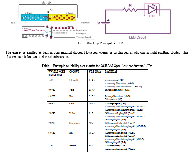
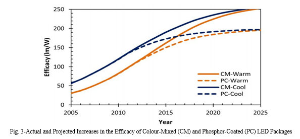
An electrical and optical phenomenon called electroluminescence occurs when an electric current is sent through a substance, causing it to emit light. The light intensity grows and reaches a maximum as the forward voltage rises. The semiconducting element's material choice affects the colour of an LED. Aluminium gallium indium phosphide alloys and indium gallium nitride alloys are the two main materials utilized in LEDs. Indium alloys are used to produce green, blue, and white light, while aluminium alloys are used to produce red, orange, and yellow light. The colour of the light that is emitted fluctuates slightly depending on the composition of these alloys.
B. Efficiency of LED
Efficacy, or more precisely, emitted flux (lumens) divided by power draw (watts), is a basic measure of power input to light output that is commonly used to characterize the energy efficiency of LED products. Despite being such a straightforward idea, there are a few crucial details that shouldn't be disregarded. For instance, the efficacy of an integrated LED lamp or an LED luminaire differs from that of LED packages, which are the individual nodes that comprise an LED product (as illustrated in Figure 1); the reasons for this distinction are driver, thermal, and optical losses. Understanding the variations in the methods and environments for measuring conventional and LED products, as well as the distinctions between products that are sold commercially and those that are developed in laboratories samples, is also essential..
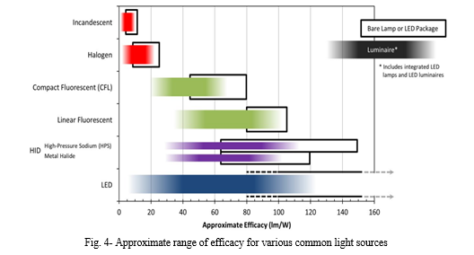
Third, a variety of currents can be used to operate LED packages. Although 700 mA, 1000 mA, and higher drive currents are also frequently available, 350 mA is the standard baseline. Efficiency droop is the term for the phenomenon wherein driving the LEDs harder, i.e., at a higher current, increases lumen output but results in a commensurate decrease in efficacy. The reason for the decline has been thoroughly examined, and it is anticipated that the detrimental impact of droop will lessen over the course of the next ten years.
Likewise, factors influencing LED package efficacy also impact lamp and luminaire performance. It is crucial to remember that the efficacy of LED packages is usually assessed using short light pulses (instead of continuous operation) at a constant ambient temperature of 25 °C, which does not reflect actual operating conditions. Furthermore, meticulous selection of the best chips makes possible some noteworthy achievements from laboratory samples, such as reports of LED packages producing over 276 Im/W. These metrics are helpful in predicting future performance even though they are not pertinent for characterizing products that are currently on the market.
Even though manufacturers usually do not report maintained efficacy, it will probably be taken into consideration if lighting calculations are made and lighting power density is assessed. A source with a lower maintained efficacy may result in higher rated power density and greater energy use at the time of installation because standard-practice calculations are based on future performance. But if two products are only compared based on their initial efficacy, this "hidden" performance might go unnoticed.
LEDs, among many other things, have popularized the idea of drawing more power in order to minimize or completely eradicate lumen depreciation. Even though this procedure isn't used very often right now, it might become more common in the future. These luminaires may at first reduce over-lighting and permit a smaller connected load, but over time, their efficacy will decline and their energy consumption will rise. This method can complicate product comparisons and may or may not result in less energy consumption over the system's lifetime.
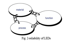
Range of approximate effectiveness for common light sources as of January 2013. The efficacy of standard lamps and LED packages, depending on their construction, materials, wattage, and other factors, is displayed by the black boxes. Luminaire efficacy, which takes into account driver, thermal, and optical losses, is represented by the shaded areas. Only LED technology is anticipated to see significant improvements in efficacy in the near future among the listed light source technologies. Although efficacy and energy efficiency are related, energy use cannot be determined by efficacy alone. Energy use, which is measured in kilowatt-hours (kWh), is the power drawn over time. If a product is used for fewer hours, it might actually consume less energy even though it is less effective. Utilizing control systems can be a valuable strategy for achieving energy savings.
C. Reliability of LED
Thus, the materials' supply chain, the production procedure, and the component's purpose all play a role in how reliable a product is (Figure 1). The final application itself must also be taken into account. Only when the changing effects and interdependencies of the constituent components are already taken into consideration during the development phase can high dependability be attained. A decline in the quality of the product and thus a fall in reliability results from completely ignoring this or concentrating just on one or two factors. The characteristic of a semiconductor element known as dependability indicates how dependably a function given to the product is carried out over time.
It is characterized by the probability of survival R(t), which is susceptible to a stochastic process. If a component can no longer perform the assigned functionality, a problem or failure is reported. Three steps are distinguished between failures and failure rates:
- Early failures
- Random or spontaneous failures
- Wear-out period
- Phase 1- the Early Failure Period
A larger failure rate can be seen in the beginning of the product lifetime, however this rate quickly declines over time. We bull distribution can be used to characterize this phase. This is typically brought on by application failures (dimensioning, handling, testing, operation, etc.) or fabricated, unsubstantiated problems. Other common causes include design flaws, material weaknesses, production quality variations, and application failures.
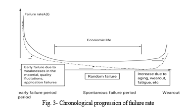
2. Phase 2- with Constant Failure Rate
This stage is the real time when something is beneficial economically. An exponential or Poisson distribution might be used to describe the continuous failure rate during this phase. Failures here tend to occur abruptly and randomly.
3. Phase 3- Wear out Failure
Due to aging, wear out, tiredness, etc. from constant use, the failure rate rises more quickly in this period. Similarly, a Weibull distribution can be used to characterize this phase. It is generally important to remember that bathtub curves are typically only based on a small number of test points when representing and interpreting them.
In actuality, it is also possible for the durations of the various phases to differ noticeably. The initial failure phase may or may not be present at all, depending on the complexity of the object and the level of maturity of the manufacturing process. It may also be defined by a time of up to a few thousand hours of operation. The failure rate over time resembles a "bathtub" curve because it is particularly high at the start and end of the product cycle. As a result, every single failure mechanism displays a unique chronological evolution and, as a result, a unique bathtub curve. The literature contains a wide variety of definitions, techniques of analysis, and mathematical formulas for reliability at each of these stages. This section and the appendix include descriptions of the most significant definitions and techniques that apply to LEDs.
The first two phases are combined into a "extrinsic reliability period" for the sake of simplicity. The "intrinsic reliability period" is the name given to the third phase, which is the wear-out period. Defective materials and manufacturing process irregularities cause extrinsic failures (early and spontaneous failures). More than 99% of these extrinsic failures are detectable during component installation (for example, soldering) during the first few hours of use. The spontaneous failure rate for LEDs, however, is incredibly low between the early failure period and the wear out period. The so-called wear-out phase of the component at the end of the product cycle is described by the intrinsic reliability period. It is based on the material's deterioration and increased wear. Degradation describes this ongoing change over time that is typically measurable. Brightness or color coordinate variations are the most important degradation characteristics for LEDs.
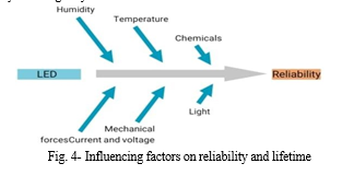
???????D. Influencing Factors with Respect to Reliability, and Lifetime
As with conventional lights, there are a number of elements that affect or can affect the dependability and durability of LED light sources. Humidity, temperature, current and voltage, mechanical forces, chemicals, and light radiation are the most significant physical influencing elements. These may directly result in total failure or may have a long-term impact on aging properties (such as brightness), changing dependability and longevity.
II. LITERATURE REVIEW
- Because of its great efficiency, light emitting diode (LED) technology is a major player in the development of lighting technologies. The world is moving toward more energy-efficient and higher-quality lighting through the use of LED lighting, which is the way of the future for both indoor and outdoor illumination solutions. On the other hand, high-power LED cooling is an essential component of LED use for optimal performance. Furthermore, because of the muds, powder, and rain, a finned heat sink's geometry and usage areas would make it inefficient. Using a computer-aided design (CAD) program, an un-finned heat sink LED armature made of aluminum sheet metal was created for this study. Additionally, using bending machines to manufacture heat sinks from sheet metal plates makes it possible to increase the variety of LED armatures at a low cost in accordance with design specifications. The system's thermal analysis was then carried out using Solid Works Simulation, a commercial finite element analysis (FEA) program, for the scenario of natural heat convection under various electrical powers and ambient temperatures. The thermal analysis produced the final heat sink sizes needed to reduce the LED junction temperature. Ultimately, the experimental research was done to confirm that the numerical solutions were feasible and that they agreed well.[7]
- This review paper's objectives are to compile a range of thermal factors that impact high-power LED performance and to provide an overview of different cooling techniques that extend the lifespan and efficiency of LED lamps. We talk about thermal factors that are appropriate for high power LED packages, including thermal resistance, thermal spreading resistance, thermal interface material, thermal capacitance, and active and passive cooling systems. Additionally investigated is the impact of junction temperature on the color of light emitted and LED life. The junction temperature of the LED is determined by the kind of cooling system and the amount of current used. Insufficient cooling when coupled with high junction temperature results in color shift and drastically reduces LED life.[12]
- The purpose of this research is to use a flat heat pipe (FHP) to enhance the thermal properties of high-power LED (light-emitting diode) packages. A novel flat heat pipe (FHP) cooling device for high power LED is developed after the heat-release characteristics of the high-power LED package are analyzed. Experimental research has been done on the thermal capabilities of high-power LED packages with flat heat pipe heat sinks, including startup performance, temperature uniformity, and thermal resistance. According to the results obtained, the LED system's total thermal resistance is 8.8 K/W, and at 3 W of input power, the junction temperature of the LED is approximately 52 1C. It is advisable to assess the effects of varying filling rates and inclination angles on the heat pipe's heat transfer performance prior to utilizing such a heat pipe cooling system structure for cooling high power LED systems.[14]
- Heat dissipation has a significant impact on the performance of high-power LEDs, which are typically used as green lighting sources because the majority of their input power is converted to heat. It is possible to access the heat conduction mode for the LED lamp radiator. The steady-state temperature distribution of the radiator is simulated using finite element simulation analysis and thermal analysis of a natural convection radiator. The simulation analysis and thermal test results are then compared. The radiator design meets the heat dissipation requirement, as demonstrated by the results, which also validate the accuracy of the thermal resistance analysis method. [8]
- This paper presents a thermal analysis of plate fin, in-line, and staggered pin fin heat sinks for a high-power LED lighting system. It also designs a 3*3 light emitting diode (LED) array with a total power of 9 W and develops a 3D one-fourth finite element (FE) model to predict the system temperature distribution. Under the same circumstances, three different types of heat sinks are compared. The temperature at which the LED chip junction occurs when the heat sink's fins are arranged alternately is found to be 48.978 C.[9]
- High-brightness LEDs have recently started to be developed for use in lighting applications. Thermal issues arise from the increased electrical currents used to drive LEDs. Thermal control for crystal rectifier modules may be a crucial design factor because high operating temperatures have a direct impact on their longevity, dependability, quality, and lightest output. In this investigation, a conductor is meant to disperse heat generated by coming into contact with a lightweight, high-power crystal rectifier. A number of crystal rectifier lights in an extremely industrial environment are the focal point of the look, which calls for cooling. Water (60 psi) is the fluid that the heat sinks are intended to use in order to properly cool the LEDs. Each conductor could be a small, semi-circular device that serves as a buffer plate to improve heat transfer. The fluid's mass flow rates fluctuated due to the parameter pertaining to specific fin styles. Four fin geometries and three mass flow rates were studied parametrically. The study's final findings suggest an Associate in Nursing optimal style that maintains the temperature of the crystal rectifier junction below check while minimizing pressure drop across all conductors.[10]
- Each conductor could be a small, semi-circular device that serves as a buffer plate to improve heat transfer. The fluid's mass flow rates fluctuated due to the parameter pertaining to specific fin styles. Four fin geometries and three mass flow rates were studied parametrically. The study's final findings suggest an Associate in Nursing optimal style that maintains the temperature of the crystal rectifier junction below check while minimizing pressure drop across all conductors. The experiment demonstrates that the radiator functions best with the light source pointing downward. In this scenario, the temperature differential between the radiator's top and bottom is at its lowest, and during operation, the temperature at the top of the radiator is higher than the bottom. The heat dissipation capabilities of the radiator's top and bottom vary when the LED lighting radiator's position changes.[11]
- Tan, Lee, and Soh (2002) suggested creating an Internet-based system in their paper to enable the monitoring of significant process variables from a distributed control system (DCS). This paper suggests hardware and software design considerations that allow the user to efficiently and remotely access the process variables on the DCS. The creation of an Internet-based system to enable critical process variable monitoring from a distributed control system (DCS) is presented in this paper. The system is designed to be an adjunct to a desktop DCS development experiment conducted by an undergraduate. This paper outlines the hardware and software design considerations that allow users to efficiently and remotely access the process variables on the DCS with just a widely used Web browser.[1]
- Potamitis, Georgila, Fakotakis, and Kokkinakis, G. (2003) proposed using speech recognition software to communicate with home appliances remotely and execute specific tasks on the user's behalf. With this approach, people with disabilities can operate appliances in their homes by speaking commands to them. The voice separation technique is chosen so that speech recognition can make the right choice. We present an integrated system that offers easy-to-use access to information and entertainment devices installed in a real home setting, using speech as a natural input modality. Speech recognition and beamforming techniques form the foundation of the system. Hands-free speech recognition in a reverberant room where users walk while conversing in the presence of various types of noise conditions specific to the house (e.g., TV/radio broadcast, interfering speakers, ventilator/air conditioner noise, etc.) is the general problem addressed in this work. The article focuses on implementation specifics and useful ideas for combining various technologies into a functional system.[2]
- In the year 2006, S. M. Anamul Haque, S. M. Kamruzzaman and Md. Ashraful Islam proposed a system entitled “A System for Smart-Home Control of Appliances Based on Time and Speech Interaction” that controls the home appliances using the personal computer. This system is developed by using the Visual Basic 6.0 as programming language and Microsoft voice engine tools for speech recognition purpose. Appliances can be either controlled by timer or by voice command. The principal aim of this project is to develop and implement a microcomputer-based system for managing electric appliances, including lights, fans, heaters, washing machines, motors, televisions, and so on. In this paper, two main methods for controlling household appliances are discussed. The first uses the timer option to control household appliances. The second method involves using voice commands to operate household appliances. Additionally, graphical user interfaces can be used to control appliances. Data from the computer is transferred to the specific device that needs to be controlled via the parallel port. To link the high-power loads to the parallel port, an interface box is needed. The ability to easily and adaptably operate household appliances will be greatly enhanced by this system for the elderly and physically disabled..[3]
- A design and implementation of SMS-based control for monitoring systems is presented by Ciubotaru-Petrescu, Chiciudean, Cioarga, and Stanescu (2006). Three modules in the paper use sensing units to monitor complex applications. A microcontroller - based processing unit and a communication module that connects to a serial port (RS-232) on a cell phone or GPRS modem. For status reporting, like power outages, the SMS is utilized. In civil environments, ranging from private residences to industrial facilities, digital systems are becoming increasingly prevalent. Because of this, there is a growing need for autonomous digital monitoring and control equipment in both domestic and industrial settings. The variety and complexity of application scenarios demanding dependable and practical solutions for remote interaction with digital systems is growing. These days, there are many options available for distant data communication thanks to advancements in telecommunications technologies, each with unique benefits and drawbacks in terms of price, bandwidth, and coverage. We are presenting a theoretical and practical approach to system design for a particular application in this paper. We have looked at a number of technologies, highlighting how effective it is to use them in various contexts depending on the features of the application. We concentrate on a specific method, a control system based on short message services, and its use in civil telemetry applications. Finally, we provide some theoretical and experimental analyses of energy consumptions, costs, and efficiency for applications that only require modest data exchanges.[4]
- Jawarkar, Ahmed, Ladhake, and Thakare (2008) propose remote monitoring through mobile phone involving the use of spoken commands. The spoken commands are generated and sent in the form of text SMS to the control system and then the microcontroller on the basis of SMS takes a decision of a particular task. Prof. Era Johri Dept. Of Information And Technology K.J.Somaiya College Of Engineering Vidyavihar, Mumbai “Remote Controlled Home Automation Using Android Application via WiFi Connectivity”. SMS is a method of sending and receiving messages to and from mobile devices. A brief message can contain up to 160 characters (text or binary). Using the GSM network, SMS messages can be sent and received concurrently with voice, fax, and data services because they use signaling channels rather than dedicated data channels for transmission and reception. The ability of SMSC to continue message delivery efforts for the designated validity period in the event that the network is currently busy or the called user is outside the coverage area, along with the provision of notification to the sender when SMS is delivered at the destination, are the main benefits of using SMS. It has been noted that many mobile users, particularly those of the older generation, find it inconvenient to enter text using a mobile keypad because it takes time and requires repeatedly pressing different keys to represent the alphabet. Spoken words are used to transmit commands for control, relieving the users of this burden.[5]
- M VIDYAVIHAR - Remote Controlled Home Automation Using Android Application via WiFi Connectivity International Journal on Recent and Innovation …, 2015 - academia.edu As the name suggests, wireless communication enables data transfer between two devices without the use of wires or cables. A cell phone can communicate with another phone without a phone cable, just as a wireless keyboard can communicate with a computer without a keyboard cable. Wireless technology can be used for a variety of tasks, including switching between computers, opening and closing garage doors, and changing television channels. In each of these situations, electromagnetic energy—also known as electromagnetic radiation—is being used to transmit and receive data. The sun is one of the most well-known sources of electromagnetic radiation; other typical sources include lightbulbs, microwaves, TV and radio signals, and others.[6]
III. METHODOLOGY
A. Component Details
The Set-Up Consisted of The Following Components:
- LED
- Heat Sink
- LED Driver
- Temperature Senso
- Receiver (panel)
- Microcontroller
- WIFI module
- Relay board
- USB TO TTL Converter
- LED
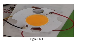
A semiconductor called a light-emitting diode (LED) produces light when electricity passes through it. Recombining electrons and electron holes in the semiconductor results in the release of energy in the form of photons. The energy needed for electrons to pass through the semiconductor's band gap determines the hue of the light, which corresponds to the energy of the photons. A layer of light-emitting phosphor or several semiconductors can be used to create white light on a semiconductor device.
In comparison to incandescent light sources, LEDs have various benefits, such as lower power consumption, a longer lifespan, increased physical resilience, smaller size, and quicker switching. Despite these largely positive characteristics, LEDs have some drawbacks, such as electrical restrictions to low voltage and typically DC (not AC) power, the inability to provide steady illumination from a pulsing DC or an AC electrical supply source, and lower maximum operating temperature and storage temperature.
Unlike LEDs, incandescent lamps can be engineered to run inherently at almost any source voltage. They can also use AC and DC current interchangeably, and they can offer continuous illumination when driven by either, even at frequencies as low as 50 Hz. While an incandescent light bulb can and frequently does work directly from an unregulated DC or AC power source, LEDs typically require electronic support components in order to perform.
???????2. Heat Sink
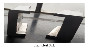
Because they provide a conduit for heat to move from the LED light source to the environment, heat sinks are a crucial component of LED lighting. Three processes can cause heat to be lost via heat sinks: conduction (heat transfer from a solid to another solid), convection (heat transmission from a solid to moving fluid, usually air), or radiation (heat transfer from two bodies with differing temperatures by thermal radiation).
How well heat dissipates by conduction is directly influenced by the material's thermal conductivity. The best heat sink material is copper, however because to its higher price, aluminum is more commonly used and makes up the majority of the heat sinks we offer here at LEDSupply. Smaller LEDs with less demanding heat dissipation requirements can be employed with thermoplastics, such as our composite LED heat sink. The usage of thermoplastics can be quite beneficial because they are significantly more lightweight and can be molded into a wider variety of shapes.
A heat exchanger called an LED heat sink absorbs the heat produced by an LED module and releases the thermal energy into the surrounding air. An LED's operating temperature has a direct impact on its spectrum performance, lumen output, and lifetime. The heatsink is one of the most crucial components of an LED lighting fixture because of this. A range of metal forming techniques, such as die casting, forging, extrusion, machining, stamping, stripping, and bonding, are used to create LED heat sinks. Casting, cold forging, extrusion, and stamping are the techniques that are employed the most frequently.
???????3. Led Driver
Similar to cruise control in a car, an LED light driver adjusts its power level when an LED's temperature rises and falls. Without the proper LED light driver, the LEDs would overheat and become unstable, which would cause them to fail and function poorly. The self-contained LED driver is necessary to provide the LED with a maintained constant quantity of power to ensure that they operate flawlessly. Low voltage and safety for the LEDs are provided by the LEDs.
Low voltage is provided by individual LED bulbs, which run at voltages between 1.5 and 3.5 volts with a maximum current of 30 mA. Domestic light bulbs can include multiple bulbs that are arranged in series and parallel and require a total voltage of 12 to 24 V DC. The LED driver corrects the AC and reduces the level to the appropriate level. By doing this, the high mains AC voltage, which ranges from 120 to 277 volts, is transformed into the necessary low DC voltage.
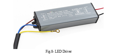
Protects LED bulbs from current and voltage fluctuations: LED drivers shield LED bulbs from current and voltage fluctuations. Regardless of changes in the mains supply, the drivers make sure that the voltage and current going to the LED lights stay within their operational range. The protection prevents supplying excessive voltage and current that would harm the LEDs or insufficient current that would lessen the amount of light produced.
???????4. Receiver (Panel)
The receiver section consists of the following components:
- WIFI receiver
-
- decoder
- ATMEGA
- Relay
- Load driver stage
-
The WiFi receiver and WiFi decoder are connected in this receiver part. The microcontroller, which is linked to the transistor driver stage, is connected to this decoder. The relay that is connected to various loads is connected to this driver.
The WIFI receiver receives radio waves that are sent by the transmitter (remote) and received by the receiver (panel) via the receiver antenna. The signals are transmitted from the WIFI receiver to the decoder, which converts them into digital data. The microcontroller receives this digital data, and depending on the code it contains, either turns on the upper/on or turns off the lower/off. The given relay (load I or load II, respectively) is correspondingly activated by this driver. The receiver section is turned on by pressing the power set or reset button. The manual switches can also be used to turn the receiver section on or off, allowing for both remote and manual operation, hence the word "hybrid" to be applied to this system.
???????5. Esp 8266:- WIFI Module
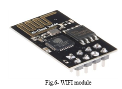
A self-contained SOC with an integrated TCP/IP protocol stack, the ESP8266 WiFi Module allows any microcontroller to access your WiFi network. The ESP8266 is capable of offloading all Wi-Fi networking tasks from another application processor or hosting an application. Each ESP8266 module is pre-programmed with an AT command set firmware, so all you need to do is connect it to your Arduino device to obtain nearly the same amount of WiFi functionality as a WiFi Shield (and that's right out of the box)! The ESP8266 module is a very affordable board with a sizable and expanding community. The ESP8266 WIFI Module is a self-contained SOC with an inbuilt TCP/IP protocol stack that can grant access to your WIFI network to any microcontroller. The ESP8266 is capable of offloading all Wi-Fi networking tasks from another application processor or hosting an application.
???????6. Relay Board
Relays are electrical devices that are typically used to control high voltages with inputs of extremely low voltage. This consists of two tiny metal flaps (nodes), which are used to close the circuit, and a coil that is wound around a pole. Two of the nodes are mobile and one is fixed. When electricity flows through the coil, a magnetic field is produced that pulls the moving node toward the static node, completing the circuit. Therefore, we may actually complete the circuit for the high voltage to travel by simply supplying a modest voltage to power up the coil.
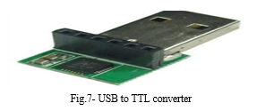
???????7. USB to TTL Converter
You can convert from USB to TTL/CMOS compatible levels and vice versa with this USB to TTL converter, which combines the USB-232-1 (USB to Single RS232 Adapter) and TTL-232-1 (Port-powered RS232/TTL converter). It can be utilized to configure the wireless APC220 Radio Data Module (SKU:TEL0005) module. It can be used to download STC microcontroller programs.
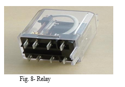
???????8. Relay
A relay is a switch that is electrically controlled. Electricity passing through the coil of the relay creates a magnetic field, which pulls a lever and changes the switch contacts. Since the coil current can be on or off, relays have two switch positions and are double-throw (changeover) switches.
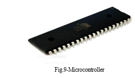
???????9. Microcontroller
The brains of our project are the microcontroller IC 89c51. We chose this microcontroller IC for our project because of the following benefits. There is no need for an external EPROM because the internal 64K bytes of electrically erasable programmable read-only memory can be used for the feeding program. Out of four 8 bit I/p o/p ports, we use one to read the DTMF decoder's output number and the other two to connect relays for operating devices. 3.5 to 6V D.C. operating voltage is readily available by employing voltage.
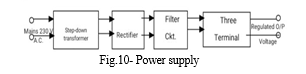
???????10. Power Supply Design
Our project's first and essential component is the power source. We need a +5V regulated power supply with a 500mA maximum current rating for our project. The following fundamental components are needed to provide a regulated power supply.
???????11. Step Down Transformer
The Step-Down Transformer Is the Initial Part of a Regulated Power Supply. For The 230V A.C Mains to Be Scaled Down, We Require a Step-Down Transformer. The Following Are an Electronic Transformer's Main Features. Power Transformers Are Frequently Designed to Operate at A Single Frequency from A Low Impedance Source. A Sufficient Amount of Insulation with The Requisite Dielectric Strength Must Be Used in Construction. Transformer Ratings Are Expressed in Volt-Amp Units. The Volt-Amp of Each Secondary Winding Is Added to Determine the Total Secondary VA. This Is Affected by The Load Losses. The Temperature Rise of a Transformer Is Determined by Two Well-Known Components, Namely Losses on The Transformer and Heat Dissipation or Cooling Facilities Given Unit.
???????12. Rectifier Unit
A rectifier transforms alternating current into pulsing direct current (ckt). Due to their ability to solely conduct current in one direction, semi-conducting diodes are frequently utilized as rectifying elements. There are typically two types of rectifiers.
a. Half wave rectifier
b. Full wave rectifier
The efficiency of a half wave rectifier is extremely low since just one half of an AC mains cycle is rectified. Therefore, we employ a full wave bridge type rectifier, which makes use of four diodes. Two diodes conduct at a time throughout each half cycle, and we achieve maximum efficiency at output.
???????13. Filter Circuit
In order to create pure D.C. supply for use at various points in the electrical circuit, a rectifier is typically needed. However, the rectifier's output has a pulsating quality, so if a D.C. with this property is applied to an electronic circuit, the result will be a hum that contains both A.C. and D.C. components. The A.C. components must be kept away from the load since they are unwanted. To accomplish this, a filter circuit is utilized, which filters out (or removes) the A.C. components before they reach the load. A filter circuit is undoubtedly put between the rectifier and voltage controller. Capacitor filters are used in our project because to their low cost, small size, light weight, and favorable characteristics. Due of the rectifier's inability to pass D.C., capacitors are connected in parallel with it.
???????14. Three Terminal Voltage Regulator
Any time the load current changes, a voltage regulator maintains a consistent voltage. IC voltage regulators are flexible and generally less expensive. Three terminal positive voltage regulators make up the 7800 series. These ICs can deliver o/p current in excess of 1A and are designed as fixed voltage regulators with an acceptable heat sink. These gadgets don't need any more parts. Additionally, this IC features intrinsic safety against thermal overload, short circuits, and current limiting. We use the voltage regulators ICs 7812 and 7805 for our project.
Conclusion
During use, LED devices produce heat, and efficient heat dissipation is essential to preserving their performance and lifetime. Thermal analysis aids in assessing the efficiency of heat sinks, thermal interfaces, and overall thermal management in an LED system\'s ability to dissipate heat. The research makes it possible to comprehend how the temperature is distributed inside the LED system or gadget. It assists in locating hotspots where heat buildup may be detrimental to the LEDs dependability or performance. Thermal analysis offers insights into the effectiveness and performance of the LED system by measuring the temperature rise and heat dissipation. Higher temperatures can result in decreased performance, quicker aging, and perhaps shorter lifespans. Strategies for efficiently dissipating heat can sustain better efficiency levels and enhance LED performance. The results of the thermal analysis can be used to direct design optimization efforts to improve the LED system\'s capacity to dissipate heat. This could entail increasing the system\'s overall thermal management or optimizing the designs of the heat sinks and thermal interfaces.
References
[1] KK Tan, TH Lee, CY Soh - Internet-based monitoring of distributed control systems-An undergraduate experiment IEEE Transactions on Education, 2002 - ieeexplore.ieee.org [2] Potamitis, K. Georgila, N. Fakotakis, G. Kokkinakis An integrated system for smart-home control of appliances based on remote speech interaction Conference on Speech …, 2003 - isca-speech.org [3] SM Haque, SM Kamruzzaman, MA Islam - A system for smart home control of appliances based on timer and speech interaction arXiv preprint arXiv:1009.4992, 2010 - arxiv.org [4] B Ciubotaru-Petrescu, D Chiciudean--Wireless solutions for telemetry in civil equipment and infrastructure monitoring -- Joint Symposium on …, 2006 - uni-obuda.hu [5] NP Jawarkar, V Ahmed, SA Ladhake, RD Thakare - Micro-controller based Remote Monitoring using Mobile through Spoken Commands. J. Networks, 2008 – Citeseer [6] M VIDYAVIHAR - Remote Controlled Home Automation Using Android Application via WiFi Connectivity International Journal on Recent and Innovation …, 2015 - academia.edu [7] Y Sümer, O Karaman, C Karaman “Design and Thermal Analysis of High Power LED Light” - European Mechanical Science, 2021 - dergipark.org.tr [8] Y Ma, Q Zhou – 2015 “Thermal analysis of high power LED light” International Industrial Informatics and …, 2015 - atlantis-press.com [9] F Hou, D Yang, G Zhang “Thermal analysis of LED lighting system with different fin heat sinks”- Journal of Semiconductors, 2011 - iopscience.iop.org [10] J Padmaja, A Ravindra “Design and Analysis of a Heat Sink for a High-Power LED System”- International Journal of Engineering …, 2015 - academia.edu [11] F Shang, C Liu, Y Wang, K Yang… - E3S Web of …, 2021 - e3s- “Experimental analysis on heat transfer performance of LED lighting radiator” conferences.org [12] A Rammohan, CK Ramesh “A Review on Effect of Thermal Factors on Performance of High-Power Light Emitting Diode (HPLED)”- Journal of Engineering …, 2016 - pdfs.semanticscholar.org [13] MS Ha - 2009 - Georgia Institute of Technology “Thermal analysis of high [14] power led arrays” [15] X Lu, TC Hua, Y Wang - Microelectronics Journal, 2011 – Elsevier “Thermal analysis of high-power LED package with heat pipe heat sink” [16] CJM Lasance, A Poppe - 2014 – Springer “Thermal management of LED light sources” [17] Kusuma S M, Assistant Professor, Department of telecommunication, MSRIT, Bangalore, India. “Home Automation Using Internet of Things.” [18] Niharika Shrotriya, Anjali Kulkarni, Priti Gadhave, International Journal of Science, Engineering and Technology Research (IJSETR), “SMART HOME USING WI-FI” [19] Anushri Aware, Sonali Vaidya, Priyanka Ashture, Varsha Gaiwal PES’s Modern College of Engineering, Pune-04, International Journal of Engineering Research and General Science Volume 3, “Home Automation using Cloud Network” [20] Thermal module design and analysis of a 230W LED illumination lamp under three incline angles- Jung-Chang Wang Microelectronics Journal (2014) 416–423 – Elsevier [21] Thermal model design and analysis of the high-power LED automotive headlight cooling device Xin-Jie Zhao, Yi-Xi Cai, Jing Wang, Xiao-Hua Li, Chun Zhang - Applied Thermal Engineering xxx (2014) 1-11 -0 – Elsevier [22] Thermal measurements and analyses of low-cost high-power LED packages and their modules -M.Y. Tsai, C.H. Chen, C.S. Kang - Microelectronics Reliability 52 (2012) 845–854 – Elsevier [23] A review of existing methods for study and analysis of thermal design of LED lighting products -Tanuja S-2013 IEEE [24] Thermal Design of a LED Multi-chip Module for Automotive Headlights -Qi Lin, Wang Chunqing, Tian Yanhong- IEEE -2012 International Conference [25] Research on LED Temperature Characteristic and Thermal Analysis at Low Temperatures -Yu Guo, Kai-lin Pan, Guotao Ren, Shu-jing Chen, Fei Yuan –IEEE 2012 International Conference [26] Thermal Analysis of Multi-chip LED Package with Different Position and Ambient Temperatures -Sze-Yen Lee, Mutharasu Devarajan -2011 IEEE [27] Study on Thermal Behaviour of LED Package at Various Ambient Temperatures -Zhi-Yin Lee, Mutharasu Devarajan -2011 IEEE [28] CJM Lasance, A Poppe - 2014 – Springer “Thermal management of LED light sources.
Copyright
Copyright © 2023 Lubdha P. Nemade, Tushar Koli, Kishor Mahajan. This is an open access article distributed under the Creative Commons Attribution License, which permits unrestricted use, distribution, and reproduction in any medium, provided the original work is properly cited.

Download Paper
Paper Id : IJRASET56685
Publish Date : 2023-11-16
ISSN : 2321-9653
Publisher Name : IJRASET
DOI Link : Click Here
 Submit Paper Online