

Ijraset Journal For Research in Applied Science and Engineering Technology
Use of Polymer in Bridge Rehabilitation
Authors: Swapnil Janjale, Abhishek Warale, Onkar Deshmukh, Onkar Adhav, Chaitanya Bhujadi , Ms. Gayatri Darandale
DOI Link: https://doi.org/10.22214/ijraset.2022.44880
Certificate: View Certificate
Abstract
Fiber reinforced polymer composite is a relatively new construction material that is slowly gaining traction among civil engineers. Bridge engineering is one of the civil engineering sectors that has benefited from the advent of FRP composite materials. Its advantages over traditional construction materials include a high tensile strength-to-weight ratio, the capacity to be moulded into diverse shapes, and potential resilience to weather conditions, all of which could result in lower maintenance costs. FRP composite is a suitable solution for creative construction because of these features. Experiments on the applicability of FRP composite in bridge structures have been undertaken over the last ten years, including FRP composite girder and bridge deck applications, column and beam strengthening, and so on. The basic knowledge of FRP composites, including mechanical characteristics and manufacturing procedures important to civil engineering applications, will be presented initially in this document. Following that, three case studies will be used to study the use of FRP composites in bridge engineering. At the conclusion, four major factors contributing to the material\'s sluggish acceptance in the construction sector as whole, despite its success in the aerospace and automobile industries, are discussed.
Introduction
I. INTRODUCTION
The building business is undergoing two big transformations. One option is through the advancement of construction processes, such as the use of automated construction tools. Another development is the advent of high-performance construction materials, such as high-strength concrete. Composites composed of fiber reinforced polymer (FRP) are one of these high-performance materials that is progressively gaining acceptance among civil engineers. The construction industry's research and development of fibers and matrix materials, as well as fabrication processes, has exploded in recent years. Their advantages over other traditional construction materials include a high tensile strength-to-weight ratio, the capacity to be moulded into various shapes, and potential resistance to weather conditions, which could result in lower maintenance costs. FRP composite is a suitable solution for creative construction because of these features. Their use in construction covers both renovating existing structures and constructing new ones, and they can be applied to a variety of constructions, including off-shore platforms, buildings, and bridges.
The development of FRP composites has benefited a variety of civil engineering sectors, including bridge engineering. Experiments on the applicability of FRP composite in bridge structures, such as FRP composite girder and bridge deck applications, column and beam strengthening, and so on, have been undertaken over the last ten years. The basic knowledge of FRP composites, including mechanical characteristics and manufacturing procedures important to civil engineering applications, will be presented initially in this document. Following that, three case studies will be used to study the use of FRP composites in bridge engineering. At the conclusion, four major factors contributing to the material's sluggish acceptance in the construction sector as whole, despite its success in the aerospace and automobile industries, are discussed.
II. OBJECTIVES
- To do an extensive study by use of fiber reinforced polymer composite in bridge structures.
- To work on fiber reinforced polymer composite in bridge structures.
- To design configuration of the bridge deck, to investigate the stress and strain at points of loading and supportsand to obtain information required for extrapolating the analysis to the full-size bridge deck.
- To use fiber reinforced polymer technique for increasing both flexural and shear capacity of concrete elements, including girders, beams, and slabs and three methods are used for application of external FRP reinforcement-adhesive bonding, hand lay-up or wet lay-up, and resin infusion.
III. LITERATURE SURVEY
FRP (fiber reinforced polymer) is a composite material formed by combining two or more materials to create a new set of qualities. FRP, on the other hand, is distinct from conventional composites in that its constituent materials are molecularlydistinct and mechanically separate.At the micro level, FRP's mechanical and physical qualities are regulated by its constituent properties and structural arrangements.
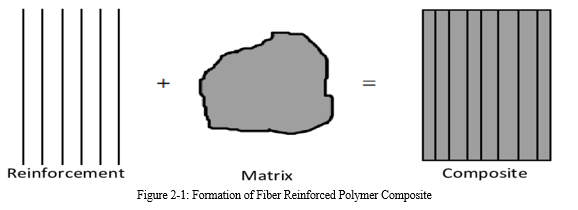
As a result, the design and analysis of every FRP structural part necessitates a thorough understanding of material properties, which are influenced by the manufacturing process as well as constituent material attributes. The anisotropic features of FRP composite come from the fact that it is a two-phased material. As illustrated in Figure 2-1, it is made up of fibre and matrix that are bonded at the interface. Each of these phases must fulfil its duty based on mechanical qualities in order for the composite system to work properly as a whole. The reinforcing fibre provides strength and stiffness to the FRP composite in this case, while the matrix provides rigidity and environmental protection.
A. Fibers
A fiber is a material that has been formed into a long filament with a diameter of around 10 tm. In continuous fibers, the length-to-diameter aspect ratio can range from thousands to infinity. The fibers' primary responsibilities in FRP are to carry load and provide stiffness, strength, thermal stability, and other structural qualities.
The fibers in a FRP composite must have the following characteristics to execute these functions:
- High modulus of elasticity for use as reinforcement;
- High ultimate strength;
- Low variation of strength among fibers;
- High stability of their strength during handling; and
- High uniformity of diameter and surface dimension among fibers.
Glass, carbon, and aramid fibers are the most common forms of fibre used in civil engineering, each with its own set of benefits and drawbacks.
|
Matrial |
Density(g/cm3) |
Tensile Modulus (E) (GPa) |
Tensile Strength (a) (GPa) |
Specific Modulus (E/c) |
Specific Strength |
Relative Cost |
|
E-glass |
2.54 |
70 |
3.45 |
27 |
1.35 |
Low |
|
S-glass |
2.5 |
86 |
4.5 |
34.5 |
1.8 |
Moderate |
|
Graphite, high modulus |
1.9 |
400 |
1.8 |
200 |
0.9 |
High |
|
Graphite, high strength |
1.7 |
240 |
2.6 |
140 |
1.5 |
High |
|
Boron |
2.6 |
400 |
3.5 |
155 |
1.3 |
High |
|
Kevlar 29 |
1.45 |
80 |
2.8 |
55.5 |
1.9 |
Moderate |
|
Kevlar 49 |
1.45 |
130 |
2.8 |
89.5 |
1.9 |
Moderate |
Table 2.1-1: Properties of Fibers
Glass fibers are a refined type of glass made from a combination of oxides, such as silica oxide from silica sand, and other raw materials like limestone, fluorspar, boric acid, and clay.
They're made by pulling molten oxides into very fine filaments with diameters ranging from 3 to 24 ptm. Chopped fibers, chopped strands, chopped strand mats, woven fabrics, and surface tissue are five types of glass fiber strands used to reinforce the matrix material.
The most prevalent forms employed in civil engineering applications are glass fibre strands and woven fabrics. Considering their inexpensive cost, glass fibers have a great strength. In the construction business, E-glass is the most often utilized glass fiber.
Aramid fibre, also known as aromatic polyamide fibre, is one of two high-performance fibresutilised in civil engineering. It's made by extruding an aromatic polyamide solution between -50 and -80 degrees Celsius into a heated cylinder at 200 degrees Celsius. Evaporated fibres are then stretched and pulled to strengthen their stiffness and strength. Aramid molecules become highly orientated in the longitudinal direction during this process.
Aramid fibres are the strongest and toughest reinforcing fibers available. They have strong impact, static, and dynamic fatigue strengths. Aramid fibers have the disadvantage of being difficult to cut and machine. Carbon fiber is another high-performance fibre that can be used in civil engineering.
They're made by pyrolyzing and crystallising organic precursors at temperatures above 2000 degrees Celsius. Carbon crystallites are generated and oriented along the fiber length in this process. Rayon precursors, polyacrylonitrile (PAN) precursors, and pitch precursors are the three types of precursors utilised in the production of carbon fibers.
B. Matrix
A matrix material is a polymer made up of molecules that are made up of numerous smaller and simpler units known as monomers. Fibers in and of themselves are useless without the presence of matrix material. To allow fibers to carry the maximum load, the matrix must have a lower modulus and greater elongation than fibers. The following are some of the most important functions of matrix material in FRP composites:
- I provide stiffness and shape to the structural member via adhesion and/or friction;
- Bind the fibers together and transfer the load to the fibers;
- Isolate the fibres so that they can act independently, resulting in slow or non-propagation of cracks;
- Protect the fibres from chemical and mechanical damage;
- Influence performance characteristics such as ductility and impact strength; and
- Provide finish colour and surface finish for connections.
The failure mechanism of the structure is also influenced by the matrix material and its compatibility with the fibers. Matrix materials come in a variety of shapes and sizes, and they can be employed in civil engineering projects. The thermoplastic and thermosetting polymers are two major types of polymers that are distinguished by their manufacturing methods and properties. Thermoplastic polymers are more ductile than thermoset polymers and have a higher tensile strength. They are, however, less stiff and strong. By simply heating and chilling them, they may be reformed and reshaped.
Thermoplastics are flexible and reformable because the molecules do not cross-link. At high temperatures, thermoplastics have weak creep resistance and are more vulnerable to solvents than thermosets. Nylon, polyetheretherketone (PEEK), polypropylene (PP), and polyphenylenesulphide are common thermoplastics (PPS).
Thermoplastics are flexible and reformable because the molecules do not cross-link. At high temperatures, thermoplastics have weak creep resistance and are more vulnerable to solvents than thermosets. Nylon, polyetheretherketone (PEEK), polypropylene (PP), and polyphenylenesulphide are common thermoplastics (PPS).
Liquid or semi-solid precursors are used to make thermosetting polymers. Polycondensation, polymerization, or curing are chemical reactions that harden these precursors.
They are turned into a hard solid at the end of the production process, resulting in a firmly connected three-dimensional network of polymer chains. Thermosetting polymers, unlike thermoplastic polymers, cannot be remeltedor reformed once they have been cured. Thermosets are notoriously fragile. They have stronger electrical, chemical, and solvent resistance, as well as higher stiffness, thermal and dimensional stability. Epoxy, polyester, vinylester, phenolics, cyanate esters, bismaleimides, and polyimides are the most popular thermosets.
|
Resin Material |
Density(g/cm3) |
Tensile ModulusGPa (10 6 psi) |
Tensile StrengthMPa (103 psi) |
|
Epoxy |
1.2-1.4 |
2.5-5.0 (0.36-0.72) |
50-110 (7.2-16) |
|
Phenolic |
1.2-1.4 |
2.7-4.1 (0.4-0.6) |
35-60 (5-9) |
|
Polyester |
1.1-1.4 |
1.6-4.1 (0.23-0.6) |
35-95 (5.0-13.8) |
|
Nylon |
1.1 |
1.3-3.5 (0.2-0.5) |
55-90 (8-13) |
|
PEEK |
1.3-1.35 |
3.5-4.4 (0.5-0.6) |
100 (14.5) |
|
PPS |
1.3-1.4 |
3.4 (0.49) |
80 (11.6) |
|
Polyester |
1.3-1.4 |
2.1-2.8 (0.3-0.4) |
55-60 (8-8.7) |
|
Polycarbonate |
1.2 |
2.1-3.5 (0.3-0.5) |
55-70 (8-10) |
|
Acetal |
1.4 |
3.5 (0.5) |
70 (10) |
|
Polyethylene |
0.9-1.0 |
0.7-1.4 (0.1-0.2) |
20-35 (2.9-5) |
|
Teflon |
2.1-2.3 |
|
10-35 (1.5-5.0) |
Table 2.2-1: Properties of Typical Unfilled Matrix Material
C. Interface
The fibers and matrix material are chemically and physically bound together at the interface. The gradient of material anisotropic characteristics can be seen in this area. This region must provide appropriate bonding stability to guarantee that the FRP composite operates successfully. In composite material analysis, it is commonly believed that the link between the fibres and the matrix material is complete, and that no strain discontinuity exists across the interface.
D. Limitation
The thickness of the element is the only limitation that is independent of the manufacturer and is reliant on material qualities. Because the resin curing process is exothermic, problems with discharging the generated heat may arise, which in severe situations might lead to spontaneous combustion. FRP in the form of wires (in particular CFRP) is an intriguing material for stay cables or tendons because of its high tensile strength, great fatigue resistance, low weight, and excellent chemical resistance. However, due to the anisotropy of the material, creating a means of anchoring the FRP cables in such a way that anchorage strength is equal to anchored cable strength is a challenge.
IV. RESULTS AND DISCUSSION
A. Case Study 1: Long-span Pedestrian Bridge
The Aberfeldy Bridge, which spans the River Tay in Scotland and was completed in 1992, is a long-span symmetrical cable-stay footbridge. It connects two sides of the Aberfeldy golf course and is the world's longest all-composite bridge. Pultruded GFRP system and aramid cables are among its revolutionary composite technologies. The dynamic behaviour of a high-performance composite bridge is one of the design difficulties, because the ratio of live load to dead load is large. The design live load for the Aberfeldy Bridge is 5.6 kN/m, with a dead weight of only 2.0 kN/m. To reduce uplift under wind and enhance transverse mass distribution, concrete ballast was inserted in the cells of the central deck panel.
- Structural Components
The Aberfeldy Bridge's deck and tower were prefabricated using the Advanced Composite Construction System (ACCS), which was made up of a variety of modular GFRP (E-glass fiber and isophthalic polyester resin) components [4]. The adoption of this prefabricated technology simplified the construction process. A 600 mm x 80 mm plank with an area of 80 mm2 was formed by combining several GFRP sections to form the primary structural parts. Each tower leg was made up of four boards and four connectors, totaling 760 mm2 of cross-sectional area [9]. Three boards and two connectors are utilized to construct the deck. Bonding and H-shaped toggle type mechanical connectors were used to join these components edge-to-edge. Edge beams reinforce the bridge longitudinally, while crossbeams, which are also made of ACCS, stiffen the bridge laterally.
Five connectors were utilised for each edge beam, while only one connector was used for each secondary crossbeam. The bridge decks were then supported by lightweight cables made from a core of parallel Kevlar49 fibres and a matrix of polyethylene. These cables were connected to 10 principal crossbeams, each with four connectors, for a total cross-sectional area of 160 mm2. Cables were inserted through the towers via 200 mm diameter steel tubes and attached to a galvanised steel plate on both sides at the tops of the towers.
2. Construction
Due to the need for dimensional correctness, the majority of the elements were pre-assembled in the factory. Two legs and a major crossbeam were included in the delivery of towers. The decks, on the other hand, were brought to the job site in 6 m long sections. Before the deck was built, the edge beams were also pre-assembled on site. It was critical that all components be maintained dry prior to and during the bonding procedure in order for the adhesive to set properly. The method of erection used for the towers was particularly distinctive due to its lightness. The towers, which were hinged to their concrete footings, were simply lifted to vertical by hand winches and guy ropes after the ground assembly was completed. The principal crossbeams and cables were then installed. The decks were dragged into place using a structure made of cable net and crossbeams. A small team completed the prefabrication and erection in under eight weeks.
3. In-Service Performance
On the bridge, two experimental investigations on the dynamic behaviour under live footfall were undertaken in 1995 and 2000. The damping ratio of the bridge, according to research, is comparable to that of an isolated deck. The energy dissipation of aramid cables is substantially lower than that of typical steel cables. Peak acceleration was 0.22g in the 1995 experiment when a person voluntarily walked on the bridge at the basic natural frequency [4].
|
Mode * |
Frequency(Hz) |
Damping ratio for empty structure (%) |
||
|
1995 |
2000 |
1995 |
2000 |
|
|
H1 |
1.00 |
0.98 |
- |
1.0 |
|
V1 |
1.56 |
1.52 |
0.84 |
0.4 |
|
V2 |
1.92 |
1.86 |
0.94 |
0.7 |
|
V3 |
2.59 |
2.49 |
1.20 |
0.7 |
|
H2 |
2.81 |
2.73 |
- |
1.2 |
|
V4 |
3.14 |
3.01 |
- |
0.8 |
|
T1 |
3.44 |
3.48 |
- |
5.5 |
|
V5 |
3.63 |
3.50 |
- |
0.6 |
|
V6 |
4.00 |
3.91 |
- |
0.9 |
|
T2 |
4.31 |
4.29 |
- |
3.2 |
|
V7 |
4.60 |
4.40 |
- |
0.8 |
|
V8 |
5.10 |
4.93 |
- |
1.8 |
*H=horizontal,V=verticle,T=torisional
Table 6.1-1: Dynamic Response of Aberfeldy Bridge, from Studies in 1995, and 2000
This acceleration exceeds the maximum permitted by BD37/88. However, due to the increased mass and stiffness after being strengthened with externally bonded GFRP pultruded plate in 1997, the observed natural frequencies in 2000 were marginally lower. In conclusion, the world's first all FRP pedestrian bridge has been performing quite well. Although there was initially a dynamic problem, this was solved by adding more mass to the bridge. Some continuing problem is delamination of FRP wearing surface, which requires constant maintenance as the bridge is still in service.
B. Case Study 2: FRP Bridge Deck
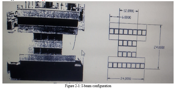
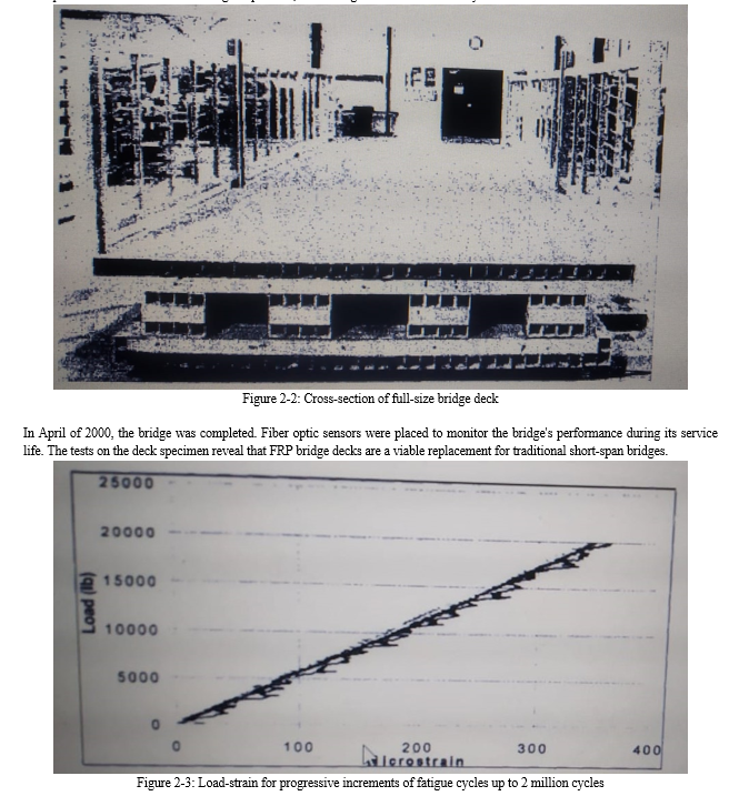
Composite material businesses and governmental authorities have collaborated on a variety of initiatives to verify and demonstrate the usage of FRP decking in bridge structures. However, a large quantity of database of FRP composite in civil engineering applications is still required in order to further establish design, testing, and manufacturing standards. As a result, the Lemay Center for Composites Technology in St. Louis, Missouri, constructed an all-FRP bridge deck. In July of 2000, it was installed on the campus of the University of Missouri at Rolla. A test programme was done on a specimen similar to a quarter of the bridge deck to check the strength, maximum deflection, and durability of the composite cross section. The deck was built to the specifications of the American Association of State Highway and Transportation Officials (AASHTO). To maintain serviceability, the deflection was kept to less than 1/800 of the span length. The load distribution requirement was determined using an AASHTO H-20 truckload of 32,000 pounds, with 16,000 pounds on each back axle [14]. The bridge deck was made out of rectangular hollow sections of pultruded carbon and glass fibers with vinylester matrix. Each section is 3 inches square with a 0.25 inch thickness [4]. Several tests were carried out using three different epoxy adhesives and various tube configurations. Finally, the main structural system was chosen to be an I-beam structure (see Figure 6.2.1). To give stiffness in both directions, tubes were put in both longitudinal and transverse orientations. Figure 6.2-1 shows how the beam was separated into eight levels. CFRP tubes were used in the second and eighth layers from the top, whereas GFRP tubes were used in the other layers. They were held together by an epoxy adhesive and a mechanical connection. Four I-beams with a total length of 30 feet and a width of 9 feet made up the bridge deck. Because of its high tensile elongation, a 0.25 inch thin polymer concrete was employed as the wearing surface. A sample was produced to the same configuration as an I beam section, which is comparable to a quarter of the bridge deck, for fatigue and ultimate load tests. The section was tested to confirm the proposed design configuration of the bridge deck, study stress and strain at loading and support locations, and acquire information needed to extrapolate the analysis to the full-size bridge deck. Design load test, fatigue or cyclic load test, and ultimate load test were the three types of tests done. The four point bending test arrangement was used for the design load and ultimate load tests. A 200,000-pound hydraulic jack was used to apply the weight. A 50,000-pound actuator was employed in the fatigue test, with the load range, frequency, and number of cycles all being regulated. The specimen was subjected to 2 million load cycles at a frequency of 4 Hz, with a minimum load of 500 lb and a maximum load of 11,000 lb. During the fatigue load test, a test for a static load of 20,000 lb was performed after every 400,000 cycles to check for stiffness loss. For the behaviour of the bridge deck, load, deflection, and strain were recorded and evaluated. The first GFRP layer was deleted after the design load test since it was deemed superfluous. The bridge deck reached an ultimate height of 21 inches. Before and after the fatigue test, the specimen's mid-span deflection at the design load was 0.26 inches and 0.31 inches, respectively. AASHTO set a limit value for these values, which were inside it. For all static loads applied during the fatigue test, the deck's deflection and strain remained nearly constant. Up to a maximum applied load of 20,000 lb, no obvious loss of stiffness was noted.
The specimen exhibits linear elastic behaviour up to a weight of 30,000 lb in the ultimate load test. Beyond this load, it began to lose stiffness, and the behaviour became non-linear. The specimen eventually failed at around 35,000 pounds, which is far more than the design load on a fifth of the bridge deck. The failure was not disastrous in the end. When the ultimate load was removed, the deck's mid-span shifted almost back to its original position, confirming the structure's ductility.
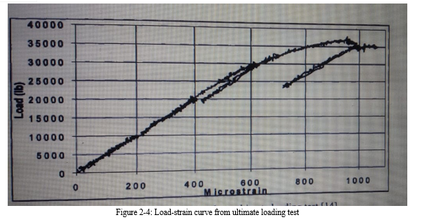
During the test, no stiffness was lost, suggesting that the FRP composite had appropriate fatigue strength. The proposed design also complies with the AASHTO guideline's requirements.
C. Case Studies 3: Pedestrian Bridge for the Boston Botanical Center Project
The Boston Botanical Center Project (BBC) is one of the Master of Engineering Program's projects for the 2004-2005 academic year. The project's major purpose is to create green areas above the Central Artery Tunnel, which was formerly occupied by a decommissioned turnpike. It is made up of three primary structures: a steel space frame on the north side, a concrete frame on the south side, and a supporting concrete pedestal. The structures on both sides are connected by a pedestrian bridge that spans Hanover Street and is supported by cables at its midpoint.
- Conventional Material Alternative
The bridge deck is made of traditional materials. Bridge girders made of steel I-beams support concrete slab portions. The wires are then connected to a north-facing space-truss arch. Steel I-beam was chosen because it helps cut down on construction time, which means less traffic disturbance.
The bridge's specs are as follows, based on simplified calculations and computer study.
a. The design live load is 100 psf;
b. W24x68 girders span 70 ft between the two halves of the garden;
c. Girders are spaced 6 ft apart and support a 2 inch thick steel plate;
d. 4 inches of concrete is placed on top of the steel plate to provide a wearing surface;
e. Use 60 ksi steel cables with a 3 inch diameter.
2. Hybrid FRP Alternative
Another pedestrian bridge design using FRP composite as the major structural element is also proposed in order to compare performance and cost. The live load and dimensions are the same as in a typical bridge. For economic and structural reasons, a hybrid FRP bridge is preferred over an all-FRP bridge.The design process closely followed the fundamental requirements and failure warnings specified in the EUROCOMP Design Code and Handbook [13], a design code for structural polymer composites. The limit state design method is commonly utilised. Ultimate limit states and serviceability limit states were the two types of limit states studied.
Ultimate limit states are those connected with structural breakdowns that may jeopardise people's safety or the ability of associated structures or components to continue operating [13]. Loss of balance or stability of the structure or any component of it, as well as failure due to severe deformation or rupture, are examples. Serviceability, on the other hand, is related to the structure's effectiveness and attractiveness. Deformation or deflection; buckling or wrinkling; vibration; cracking, delamination, and local FRP composite damage are all examples.When designing any FRP structure or component, all applicable limit states must be taken into account. The stress-strain relationship of FRP is believed to be linear in most cases. FRP can display little or no ductile behavior beyond this threshold of linearity, which must also be considered. As a result, stiffness requirements, both in terms of deflection and buckling, tend to drive FRP design.While this necessitates careful section selection for stiffness and stability, considerable strength will be required to ensure that the structure breaks in the serviceability limit state before reaching the ultimate limit state. When building a FRP beam for flexure, the stability of the flange to resist compression and the web to resist shear must be considered in the form of a width-to-thickness ratio. Deflections caused to bending and shear deformations must be verified for serviceability. Equations for a conventional, isotropic, homogeneous beam can be used to compute deflections.
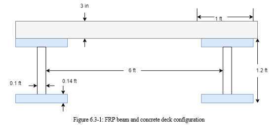
The FRP beam was intended to withstand a service live load of 100 pounds per square foot and a construction live load of 20 pounds per square foot. For the prefabricated I-beam portion, pultruded E-glass with polyester, vinylester, and modar as matrix was chosen. The pultrusion technique yielded a fibre volume fraction of 0.48, which should be sufficient for the strength required in this application. For cost reasons, the bridge deck will be a 3 inch thick concrete slab rather than a FRP composite. Each beam will have to carry a dead load of 225 lb/ft due to the bridge deck, a service live load of 600 lb/ft, and a construction live load of 120 lb/ft when spaced evenly every 6 ft. A maximum deflection of 1/800 of the overall span is allowed.The primary objective was to create a hybrid FRP bridge with the same deflection as a conventional bridge. However, it turned out that the design was governed by the flange's stability under compressive stress.Figure 6.3-1 depicts the ultimate dimension of FRP.
3. Computer Analysis
A computer tool called SAP2000 is used to examine these two design options. This computer application has a wide range of capabilities, including the ability to analyze structures both statically and dynamically. Both bridges were represented as simply supported beams with load distribution that was uniform.The deck of a standard bridge is made up of steel plates and concrete deck, as detailed in the specification section. The steel plate is used to create a shape for pouring concrete on the deck. However, in the model, these two materials are grouped together for the composite element, based on the transformed cross-section principle. The addition of 16" of concrete deck thickness is achieved by using steel plate and concrete with elastic moduli of 29,000 ksi and 3,600 ksi, respectively. The computer then creates bridge decks as shells, each supported by two I-beams. These I-beams in the model are simply supported in order to approximate the behaviour of expansion joints. The shell is subjected to a 100 psf live load.The traditional bridge was modelled in the same way as the hybrid FRP bridge.
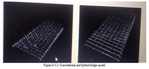
To account for orthotropic qualities, material properties were changed. Appendix A illustrates the use of GFRP. The concrete deck, which was conceived as a shell, was simply supported and carried by GFRP I-beams. Each beam was broken into smaller eight pieces in order to replicate the behavior of the adhesive junction between concrete and I-beams. At four nodes, a concrete shell and a beam are linked.Table 6.3-1 compares the greatest deflection and dynamic characteristics of the two options.
|
|
Conventional |
Hybrid FRP |
|
Maximum deflection(ft) |
0.16 |
0.15 |
|
Fundamental Period(Sec) |
0.36 |
3.8 |
Table 3-1: Result from static and dynamic analysis of the two alternatives
4. Construction
Because typical prefabricated steel sections are utilised in the traditional bridge, construction is not overly complicated. The employment of a cable and arch support system, on the other hand, adds a technical constraint to the construction process. Construction is divided into two stages. The wide flange steel beams are first laid across Hanover Street by crane. This phase can be completed in two night shifts, which means the street will be closed only during those hours [15]. The girders will next be covered in galvanised steel plate, which will serve as formwork for the concrete wearing surface. A total of 6 inches of concrete is poured to create the deck.
Due to its prefabricated elements, the hybrid FRP bridge may be built in the same amount of time as a conventional bridge. The lack of weight also reduces the requirement for a heavy machine to be mobilised. Epoxy adhesive can be used to attach the concrete surface to the FRP deck. Although it is difficult to predict how long the bridge will take to build, it is plausible to expect that it will take less time than a conventional bridge. This assumption, however, will only hold true provided construction personnel have appropriate experience handling and installing FRP composite structures. The technique of using adhesive to link a concrete slab with a FRP beam is complicated. Before applying adhesive, the concrete surface must be prepared to ensure a high binding strength. This technique necessitates a great deal of attention and experience, which may cause delays in the construction process.
5. Cost Estimate
When comparing the costs of two alternatives made of FRP composite and conventional material, basic material costs, construction expenses, and long-term costs must all be considered. Appendix B contains the material amounts and costs. Table 6.3-2 compares the total material and construction costs of the two options. The hybrid FRP bridge is significantly less expensive than the standard bridge when only material and construction expenses are considered. However, the price may have been reduced to $206,527 if a cable-arch system was added to the standard bridge for deflection control and aesthetics.
|
Alternative |
Component |
Quantity |
Cost |
|
Traditional |
concrete on steel deck (ft) |
10070 |
$37,762.50 |
|
|
steel girders (ft 3 ) |
221.81 |
$163,030.35 |
|
|
steel cables |
800 |
$60,000.00 |
|
|
steel truss arch (ft3) |
1430 |
$1,051,050.00 |
|
|
concrete arch column (ft= ) |
1529 |
$5,733.75 |
|
|
|
Total: |
$1,317,576.60 |
|
Hybrid GFRP |
concrete deck (ft3) |
2310 |
$8,662.50 |
|
|
GFRP I-beams (kg) |
34929.01 |
$322,045.47 |
|
|
epoxy resin |
n/a |
n/a |
|
|
|
Total: |
$330,707.97 |
Table 3-2: Total material and construction costs
As a result, the hybrid FRP bridge is 60% more expensive than a standard bridge. The usage of FRP composite is projected to assist minimize some indirect expenses, such as building time, as well as long-term expenditures, such as maintenance. Because the structural systems in these two examples are so similar, the same building process can be applied in both cases. In this scenario, saving construction time is debatable. FRP composite's environmental, chemical, and mechanical resistance offers the ability to reduce maintenance costs. However, at this stage of the project, quantifying it is challenging.
Conclusion
FRP composite is a two-phased material made by combining two or more constituent materials. Its advantages, in term of mechanical behaviors and durability, can be predetermined during manufacturing process. A number of manufacturing processes are available for producing structural members used in civil engineering applications. According to the case studies, FRP composite is a potential construction material for bridge engineering. It has several advantages over traditional materials. These include its high strength to weight ratio; its potential resistance to environmental and chemical damages. However, its acceptance into bridge engineering industry is quite slow. Issues contributing to this are cost, structural performance, nature of FRP composite industry and code specifications, and durability. Before it is fully accepted as practical construction material, more projects involving FRP composite are still needed to verify its long-term cost-saving and in-service durability. High Specific Strength and Stiffness.
Copyright
Copyright © 2022 Swapnil Janjale, Abhishek Warale, Onkar Deshmukh, Onkar Adhav, Chaitanya Bhujadi , Ms. Gayatri Darandale. This is an open access article distributed under the Creative Commons Attribution License, which permits unrestricted use, distribution, and reproduction in any medium, provided the original work is properly cited.

Download Paper
Paper Id : IJRASET44880
Publish Date : 2022-06-25
ISSN : 2321-9653
Publisher Name : IJRASET
DOI Link : Click Here
 Submit Paper Online