

Ijraset Journal For Research in Applied Science and Engineering Technology
Wind Analysis of RCC Tube in Tube Structure
Authors: Miss. Sapana Bore, Prof. R. M. Desai
DOI Link: https://doi.org/10.22214/ijraset.2022.47703
Certificate: View Certificate
Abstract
Modern tall buildings have efficient structural systems, and utilize high-strength materials, resulting in reduced building height, and thus, become slenderer and more flexible with low damping. These flexible buildings are very sensitive to wind excitation and earthquake load causing discomfort to the building occupants. Therefore, in order to mitigate such an excitation and to improve the performance of tall buildings against wind loads and earthquake loads, the tube in tube structures and tube frame structures are the innovative and fresh concept in the tubular structures. Generally, tube in tube structures is formed by connecting peripheral frame tube and inner core tube so closely, it is not seen as a solid system but it acts like a solid surface. The total loads acting on the structures to be collectively shared between the inner and outer tubes. The tubed frames Structure are new concept for tall building. In tubed mega frames instead of one central tube several vertical tubes are carrying the lateral loads. a comparative study of tube in tube structures and tubed mega frame system with different building geometry has been done using ETABS software.
Introduction
I. INTRODUCTION
The advancement in construction field is increased day by day. The numbers of buildings, height of building is increased. The effect of lateral load is increased with respect to the increase of height. Modern construction methods and structural systems are to be introduced to enhance the structural safety. There are different types of structural systems which are to be used to resist the effect of lateral loads on the buildings. Rigid frame structures, braced frame structures, shear wall frame structures, outrigger systems, tubular structures are the different types of structural systems used in the buildings to enhance structural safety by reduce the effect of lateral loads on the buildings. The tubular systems are widely used and considered as a better structural system for tall buildings. There are different types of tubular structural systems which are given as framed tube, braced tube, bundled tube, tube in tube, and tube mega frame structures tubular structures. Nowadays, tubular constructions have become increasingly prevalent in tall buildings. Tube in tube structures are ideally suited for any tall structures. A tube-in- tube structure consists of a framed peripheral tube and a core tube that are joined by floor slabs. The overall structure resembles a large tube with a smaller tube in the centre. Both the inner and outer tubes share lateral loads. This paper includes an investigation of the vulnerability of different tubed structures to large wind loads when built as tube-in- tube structures and bundled tube structures. Tube-in-tube structures and bundled tube structures are unique and novel tubular structure concepts. In this project, ETABS software was used to conduct a comparison of tube- in-tube structure and bundled tube structures. Using ETABS, the modelling and analysis are performed.
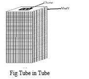
II. CONCEPT OF TUBE IN TUBE STRUCTURE
This is a type of framed tube consisting of an outer-framed tube together with an internal elevator and service core. The exterior tube and the interior tube are designed to act together. The exterior tube has relatively large width and hence it is designed to resist the entire bending moment caused by lateral forces. The interior tubes are designed to carry shear produced by the lateral forces. This type of structures is also called as Hull (Outer tube) and Core (Inner tube) structures.
III. PROBLEM FORMULATION
A. Proposed Work
After exclusive study of literature carried by various researchers, the unfocused area is identified as problem for proposed dissertation. carried out using following points
- To study parametric design variables on the performance of a G+25 story building with different basic wind speed in terrain category II.
- Comparative wind analysis between tube in tube RCC structure with story open at every 5th floor.
IV. MODEL PROPERTIES
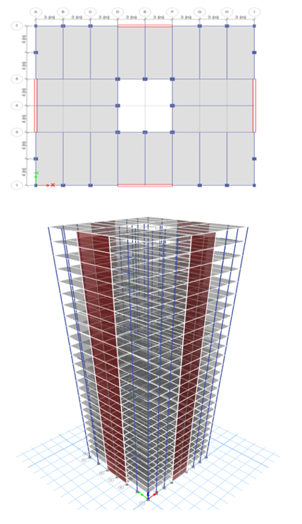
G+25 storied building with different wind speeds, storey open at different levels with basic wind speed 39 m/s and different shapes i.e. hexagonal, octagonal, square and rectangular are model using conventional beams, columns, shear walls & slabs. They are loaded with Dead, Live, wind and Seismic Forces (according to IS 875:2015(Part-3) and IS:1893:2016). These models are then analysed using wind analysis method for earthquake zone 3 of India (Zone Factor = 0.16). The details of the modelled building are listed below.
Mechanical Property of Reinforcement Steel
|
Floors |
Sizes(mm) |
|
|
Corner |
Others |
|
|
G-G4 |
530X530 |
450X800 |
|
G5-G6 |
500X500 |
450X750 |
|
G7-G10 |
450X500 |
450X700 |
|
G11-G15 |
450X450 |
450X600 |
|
G16-G20 |
450X380 |
450X500 |
|
G21-G25 |
450X300 |
450X450 |
A. Types of Loads
Unless otherwise specified, all loads listed, shall be considered in design for the Indian Code following load combinations shall be considered.
Load case
- DL: Dead load
- LL: Live load
- EQ: Earthquake load
B. Load Combination
|
1.5 (DL + LL) |
1.2 (DL + LL ± WLX) |
0.9DL ± 1.5WLX |
|
1.2 (DL + LL ± EQX) |
1.2 (DL + LL ± WLY) |
0.9DL ± 1.5WLY |
|
1.2(DL + LL ± EQY) |
1.5(DL ± WLX) |
0.9DL ± 1.5EQX |
|
1.5(DL ± EQX)
1.5(DL ± EQY) |
1.5(DL ± WLY) |
0.9DL ± 1.5EQY |
Where,
DL = Dead load, LL = Live load
EQX and EQY = Earthquake load in X and Y direction WLX and WLY = Wind load in X and Y direction.
V. SOFTWARE PLAN AND 3D MODEL
VI. RESULTS
A. Displacement due to Wind
Displacement dur to wind in different basic wind speed in X- direction.
|
Story |
Displacement (mm) |
|||
|
Model 1 |
Model 2 |
Model 3 |
Model 4 |
|
|
Story26 |
39.566 |
50.362 |
57.463 |
65.033 |
|
Story25 |
38.631 |
49.172 |
56.105 |
63.496 |
|
Story24 |
37.654 |
47.927 |
54.686 |
61.89 |
|
Story23 |
36.62 |
46.612 |
53.185 |
60.191 |
|
Story22 |
35.517 |
45.207 |
51.582 |
58.377 |
|
Story21 |
34.334 |
43.702 |
49.865 |
56.434 |
|
Story20 |
33.067 |
42.09 |
48.025 |
54.352 |
|
Story19 |
31.715 |
40.369 |
46.061 |
52.129 |
|
Story18 |
30.274 |
38.535 |
43.969 |
49.761 |
|
Story17 |
28.745 |
36.588 |
41.747 |
47.247 |
|
Story16 |
27.13 |
34.532 |
39.401 |
44.592 |
|
Story15 |
25.432 |
32.371 |
36.936 |
41.801 |
|
Story14 |
23.662 |
30.119 |
34.366 |
38.893 |
|
Story13 |
21.822 |
27.777 |
31.693 |
35.869 |
|
Story12 |
19.92 |
25.355 |
28.93 |
32.741 |
|
Story11 |
17.964 |
22.866 |
26.09 |
29.527 |
|
Story10 |
15.968 |
20.325 |
23.191 |
26.246 |
|
Story9 |
13.95 |
17.756 |
20.26 |
22.929 |
|
Story8 |
11.924 |
15.178 |
17.318 |
19.599 |
|
Story7 |
9.914 |
12.618 |
14.398 |
16.294 |
|
Story6 |
7.946 |
10.115 |
11.541 |
13.061 |
|
Story5 |
6.059 |
7.712 |
8.8 |
9.959 |
|
Story4 |
4.302 |
5.476 |
6.248 |
7.071 |
|
Story3 |
2.729 |
3.474 |
3.964 |
4.486 |
|
Story2 |
1.417 |
1.804 |
2.058 |
2.329 |
|
Story1 |
0.468 |
0.596 |
0.68 |
0.77 |
|
Base |
0 |
0 |
0 |
0 |
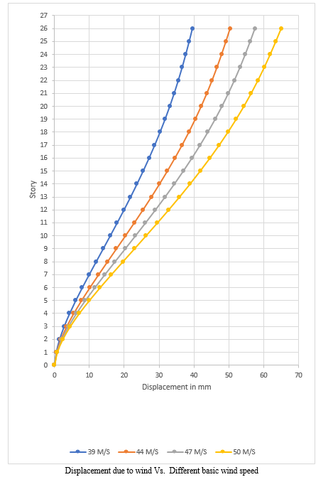
Analysis of RCC tube in tube structure with different basic wind speed i.e., 39m/sec, 44m/sec, 47m/sec and 50m/sec with medium soil condition at zone III has been done. The displacement in x and y direction due to wind of structure with basic wind speed 44m/s, 47m/s, and 50m/s is increased 22%, 31% and 39% as compared to 39m/s basic wind speed.
B. Story Drift
Story Drift At different basic wind speed and earthquake zone III in X-direction.
|
Story |
Story Drift |
|||
|
|
Model 1 |
Model 2 |
Model 3 |
Model 4 |
|
Story26 |
0.000312 |
0.000397 |
0.000453 |
0.000512 |
|
Story25 |
0.000326 |
0.000415 |
0.000474 |
0.000536 |
|
Story24 |
0.000345 |
0.000439 |
0.0005 |
0.000566 |
|
Story23 |
0.000368 |
0.000468 |
0.000534 |
0.000605 |
|
Story22 |
0.000394 |
0.000502 |
0.000572 |
0.000648 |
|
Story21 |
0.000422 |
0.000538 |
0.000613 |
0.000694 |
|
Story20 |
0.000451 |
0.000574 |
0.000655 |
0.000741 |
|
Story19 |
0.00048 |
0.000611 |
0.000698 |
0.000789 |
|
Story18 |
0.00051 |
0.000649 |
0.00074 |
0.000838 |
|
Story17 |
0.000538 |
0.000685 |
0.000782 |
0.000885 |
|
Story16 |
0.000566 |
0.00072 |
0.000822 |
0.00093 |
|
Story15 |
0.00059 |
0.000751 |
0.000857 |
0.00097 |
|
Story14 |
0.000613 |
0.000781 |
0.000891 |
0.001008 |
|
Story13 |
0.000634 |
0.000807 |
0.000921 |
0.001042 |
|
Story12 |
0.000652 |
0.00083 |
0.000947 |
0.001071 |
|
Story11 |
0.000665 |
0.000847 |
0.000966 |
0.001094 |
|
Story10 |
0.000673 |
0.000856 |
0.000977 |
0.001106 |
|
Story9 |
0.000675 |
0.000859 |
0.000981 |
0.00111 |
|
Story8 |
0.00067 |
0.000853 |
0.000973 |
0.001102 |
|
Story7 |
0.000656 |
0.000835 |
0.000952 |
0.001078 |
|
Story6 |
0.000629 |
0.000801 |
0.000914 |
0.001034 |
|
Story5 |
0.000586 |
0.000745 |
0.00085 |
0.000963 |
|
Story4 |
0.000524 |
0.000667 |
0.000761 |
0.000862 |
|
Story3 |
0.000437 |
0.000557 |
0.000635 |
0.000719 |
|
Story2 |
0.000316 |
0.000403 |
0.000459 |
0.00052 |
|
Story1 |
0.000157 |
0.0002 |
0.000229 |
0.000259 |
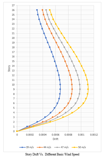
The story drift of structure with different basic wind speeds has been analyzed and it has been seen that story drift in X- direction is more for 9th floor and in Y-direction is more for 11th floor. It has been seen that in model 1 story drift reduces by 26.81%, 45.33% and 62% as compared to model 2, model 3 and model 4 respectively.
C. Comparative wind analysis between tube in tube RCC structure with story open at every 5th floor.
The Wind Analysis of tube in tube structure with open story at every 5th story has been done for same model with different basic wind speeds as given in 4.3 section. The calculations have done manually and in excel sheets because it is not possible to show the open story in software. After calculations, the values have been put in wind load cases in software and done the analysis. Following are the results,
D. Displacement Due to Wind
Displacement due to wind in different basic wind speed
|
Story |
Displacement (mm) |
|||
|
|
Model 1 |
Model 2 |
Model 3 |
Model 4 |
|
Story26 |
27.853 |
35.428 |
40.451 |
45.78 |
|
Story25 |
27.178 |
34.57 |
39.472 |
44.671 |
|
Story24 |
26.473 |
33.673 |
38.448 |
43.513 |
|
Story23 |
25.73 |
32.727 |
37.368 |
42.291 |
|
Story22 |
24.938 |
31.719 |
36.218 |
40.989 |
|
Story21 |
24.091 |
30.642 |
34.988 |
39.597 |
|
Story20 |
23.186 |
29.49 |
33.674 |
38.109 |
|
Story19 |
22.222 |
28.263 |
32.274 |
36.525 |
|
Story18 |
21.197 |
26.959 |
30.785 |
34.84 |
|
Story17 |
20.111 |
25.578 |
29.208 |
33.056 |
|
Story16 |
18.967 |
24.121 |
27.546 |
31.175 |
|
Story15 |
17.766 |
22.594 |
25.803 |
29.202 |
|
Story14 |
16.517 |
21.005 |
23.989 |
27.149 |
|
Story13 |
15.221 |
19.355 |
22.106 |
25.018 |
|
Story12 |
13.882 |
17.653 |
20.162 |
22.818 |
|
Story11 |
12.509 |
15.906 |
18.168 |
20.561 |
|
Story10 |
11.109 |
14.126 |
16.135 |
18.26 |
|
Story9 |
9.697 |
12.33 |
14.083 |
15.938 |
|
Story8 |
8.281 |
10.529 |
12.026 |
13.611 |
|
Story7 |
6.877 |
8.745 |
9.988 |
11.304 |
|
Story6 |
5.507 |
7.002 |
7.997 |
9.051 |
|
Story5 |
4.193 |
5.332 |
6.09 |
6.893 |
|
Story4 |
2.973 |
3.781 |
4.318 |
4.887 |
|
Story3 |
1.883 |
2.394 |
2.735 |
3.095 |
|
Story2 |
0.975 |
1.24 |
1.416 |
1.603 |
|
Story1 |
0.321 |
0.408 |
0.466 |
0.527 |
|
Base |
0 |
0 |
0 |
0 |
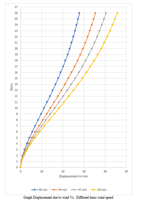
The wind analysis has been done with different basic wind speeds with story open at every 5th story. From that wind displacement is increased about 30% in tube in tube structure with different wind speeds as compared to tube in tube structure with story open at every 5th level.
E. Story Drift
Story Drift At different basic wind speed and open story at different level in X-direction.
|
Story |
Story drift |
|||
|
|
Model 1 |
Model 2 |
Model 3 |
Model 4 |
|
Story26 |
0.000225 |
0.000286 |
0.000327 |
0.00037 |
|
Story25 |
0.000235 |
0.000299 |
0.000342 |
0.000387 |
|
Story24 |
0.000248 |
0.000315 |
0.00036 |
0.000407 |
|
Story23 |
0.000264 |
0.000336 |
0.000383 |
0.000434 |
|
Story22 |
0.000282 |
0.000359 |
0.00041 |
0.000464 |
|
Story21 |
0.000302 |
0.000384 |
0.000438 |
0.000496 |
|
Story20 |
0.000321 |
0.000409 |
0.000467 |
0.000528 |
|
Story19 |
0.000342 |
0.000435 |
0.000496 |
0.000562 |
|
Story18 |
0.000362 |
0.00046 |
0.000526 |
0.000595 |
|
Story17 |
0.000381 |
0.000485 |
0.000554 |
0.000627 |
|
Story16 |
0.0004 |
0.000509 |
0.000581 |
0.000658 |
|
Story15 |
0.000416 |
0.00053 |
0.000605 |
0.000684 |
|
Story14 |
0.000432 |
0.00055 |
0.000628 |
0.00071 |
|
Story13 |
0.000446 |
0.000567 |
0.000648 |
0.000733 |
|
Story12 |
0.000458 |
0.000582 |
0.000665 |
0.000752 |
|
Story11 |
0.000467 |
0.000593 |
0.000678 |
0.000767 |
|
Story10 |
0.000471 |
0.000599 |
0.000684 |
0.000774 |
|
Story9 |
0.000472 |
0.0006 |
0.000685 |
0.000776 |
|
Story8 |
0.000468 |
0.000595 |
0.000679 |
0.000769 |
|
Story7 |
0.000457 |
0.000581 |
0.000664 |
0.000751 |
|
Story6 |
0.000438 |
0.000557 |
0.000636 |
0.000719 |
|
Story5 |
0.000407 |
0.000517 |
0.000591 |
0.000668 |
|
Story4 |
0.000363 |
0.000462 |
0.000528 |
0.000597 |
|
Story3 |
0.000303 |
0.000385 |
0.000439 |
0.000497 |
|
Story2 |
0.000218 |
0.000278 |
0.000317 |
0.000359 |
|
Story1 |
0.000108 |
0.000137 |
0.000157 |
0.000177 |
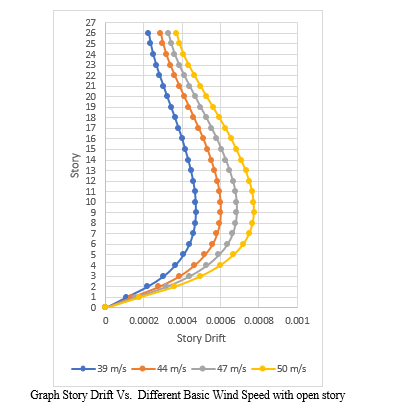
The story drift of structure with different basic wind speeds has been analyzed and it has been seen that story drift in X- direction is more for 9th floor and in Y-direction is more for 11th floor. It has been seen that in model 1 story drift reduced by 27.11%, 43.85% and 64.40% as compared to model 2, model 3 and model 4 respectively.
Conclusion
1) The wind displacement of model 2, model 3 and model 4 is increased by 22%, 21% and 39% as compared to model 1. Also, the base shear of model 1 due to wind load in x and y direction is less by 21.43%, 31.14% and 39.16 % for model 2, model 3, and model 4 respectively. 2) Analysis of RCC tube in tube structure and tube in tube with open story structure has been done and it has been seen that overall performance of tube in tube structure with story open at different level is healthier than remining all structure. The wind displacement is increased about 30% in normal tube in tube structure as compared to tube in tube structure story open at every 5th level. 3) The story drift in normal tube in tube structure and tube in tube with open story structure is within permissible limits so structure shows linear behavior. It has been seen that in model 1 story drift reduces by 26.81%, 45.33% and 62% as compared to model 2, model 3 and model 4 respectively at 9th and 11th floor.
References
[1] Shilpa Balakrishnan (2019) “Comparative Study on Tube in Tube and Tubed Mega Frames on Different Building Geometry Using ETABS”. Int. Journal of Applied Sciences and Engineering Research, Vol. 1, Issue 4, 2012 www.ijaser.com © 2012 by the authors – Licensee IJASER- Under Creative Commons License 3.0 editorial@ijaser.com Research article ISSN 2277 – 9442. [2] Ashitha V Kalam et.al (2019) “Dynamic wind analysis of RC bundled tube in tube structure using ETABS software” International Research Journal of Engineering and Technology (IRJET) e-ISSN: 2395-0056Volume: 06 Issue: 05 May 2019. [3] C. V. Siva Rama Prasad, Bhavani.K,Linga Raju.J, Prashanth.M (2019) “Seismic and Wind analysis of a multi-story building (G+12) by using ETABS software©”, JETIR March 2019, Volume 6, Issue 3 www.jetir.org (ISSN-2349-5162) [4] Okafor C. Vincent, Kevin C. Okolie, Mbanusi C. Echefuna, and Okafor C. Pamela (2017) “Analysis of Wind Effect on High-Rise Building for Different Terrain Category”. EJERS, European Journal of Engineering Research and Science Vol. 2, No. 12, December 2017.
Copyright
Copyright © 2022 Miss. Sapana Bore, Prof. R. M. Desai. This is an open access article distributed under the Creative Commons Attribution License, which permits unrestricted use, distribution, and reproduction in any medium, provided the original work is properly cited.

Download Paper
Paper Id : IJRASET47703
Publish Date : 2022-11-25
ISSN : 2321-9653
Publisher Name : IJRASET
DOI Link : Click Here
 Submit Paper Online