

Ijraset Journal For Research in Applied Science and Engineering Technology
Wind Analysis of RCC Tube in Tube Structure Using ETABS Software
Authors: Abhishek Wadde, Dr. Uttam Awari
DOI Link: https://doi.org/10.22214/ijraset.2022.48468
Certificate: View Certificate
Abstract
The advancement in construction field is increased day by day. The numbers of buildings, height of building is increased. The effect of lateral load is increased with respect to the increase of height. Advance construction methods and structural systems are to be introduced to enhance the structural safety. There are different types of structural systems which are to be used to resist the effect of lateral loads on the buildings. tube, bundled tube, tube in tube, and tube mega frame structures tubular structures. A tube-in-tube structure Comprises of a peripheral framed tube and a core tube interconnected by floor slabs. The frame tube structure takes more of lateral load the efficiency of this system is derived from the great number of rigid joints acting along the periphery, creating a large tube. In which the horizontal slabs and beams connecting vertical elements are assumed as continuous connecting medium having Equivalent distributed stiffness properties. The tube-in-tube structure with central tube provides stability against lateral loading as well as gravity loading. The Static analysis is use for analysis of tubular structures and the output of the models are evaluate to have a comparative study of their wind performance in different terrain, Also, this system provides enough opening for stairways, elevators and ducts etc. It is suitable for high rise structure. The use of tube-in-tube structure allows speedy construction. It is suitable for RCC, constructions. This study is focused on wind behavior of tube in tube structure for varying terrain category in India for the parameters like wind displacement, story drift, and time period.
Introduction
I. INTRODUCTION
A. General Introduction
The advancement in construction field is increased day by day. The numbers of buildings, height of building is increased. The effect of lateral load is increased with respect to the increase of height. Modern construction methods and structural systems are to be introduced to enhance the structural safety. There are different types of structural systems which are to be used to resist the effect of lateral loads on the buildings. Rigid frame structures, braced frame structures, shear wall frame structures, outrigger systems, tubular structures are the different types of structural systems used in the buildings to enhance structural safety by reduce the effect of lateral loads on the buildings. The tubular systems are widely used and considered as a better structural system for tall buildings. There are different types of tubular structural systems which are given as framed tube, braced tube, bundled tube, tube in tube, and tube mega frame structures tubular structures.
In recent years, tall buildings and structures have become slenderer, which increases the likelihood of excessive sway compared to older tall buildings. This creates additional difficulties for the engineering sector in resisting both lateral loads, such as wind and earthquake loads, and gravity loads. In the past, engineers primarily considered gravity loads when designing structures, but in recent years, due to the growth in height and seismic zone, they also consider lateral loads caused by wind and seismic forces. The height of tall structures is a comparative word. There is no globally applicable, precise definition for tall constructions. From a structural engineering standpoint, all tall structures must withstand both gravity and lateral loads. Due to the influx of a large population, towns and cities are expanding at a rapid rate. This phenomenon can be observed on every continent. The lack of available land for construction, especially in the world's biggest cities, is a widespread issue that has led to the vertical rather than horizontal development of structures. Today, high-rise commercial structures are symbols of modern society. These represent the strength of commerce in the current global economy. These also give the city a third dimension.
Additionally, on a micro level, having a commercial space in a beautiful high-rise structure provides the firm with additional benefits in terms of increased client confidence and brand recognition. Globally, major towns and cities are constructing high-rise buildings with a very large number of stories, and India is not an exception to this trend. Tall structures comprised of a framework with multiple stories are flexible and vulnerable to the effect of wind forces.
To resist the effect of lateral loads on the buildings, several structural systems must be employed. There are tube structures, rigid frame structures, braced frame structures, shear wall frame structures, outrigger systems, and braced frame structures. The tubular systems are widely employed and are regarded as the superior lateral structural solutions for high-rise buildings. The tubular constructions are subdivided into frame tube, braced tube, bundled tube, tube inside tube, and tube mega frame structures. Tube-in-tube structures and bundled tube structures are unique and novel tubular structure concepts. In towering buildings, tube-in-tube constructions will be increasingly utilized. In the subject of tubular constructions for tall buildings, bundled tube structures are the new concept. Nowadays, tubular constructions have become increasingly prevalent in tall buildings. Tube in tube structures is ideally suited for any tall structures. A tube-in- tube structure consists of a framed peripheral tube and a core tube that are joined by floor slabs. The overall structure resembles a large tube with a smaller tube in the centre. Both the inner and outer tubes share lateral loads. This paper includes an investigation of the vulnerability of different tubed structures to large wind loads when built as tube-in- tube structures and bundled tube structures. Tube-in-tube structures and bundled tube structures are unique and novel tubular structure concepts. In this project, ETABS software was used to conduct a comparison of tube- in-tube structure and bundled tube structures. Using ETABS, the modelling and analysis are performed.
B. Wind Effect on Tall Buildings
Since the wind varies over time, the wind spectrum and natural frequencies can be used to describe the difference in wind-related structural design of a typical high-rise building. In general, wind pressure and the resulting structural response are regarded as stationary random processes in which the time-averaged or mean component is separated from the fluctuating component. Tall buildings bluff bodies, and when wind blows against them, vortices are generated that result in an alternating force perpendicular to the direction of the wind. When the phenomena of vortex shedding occur along a substantial portion of the building's height, it can result in high forces and amplitudes. Wind loads linked with gustiness or turbulence produce substantially higher building responses than steady application of the same loads. Therefore, wind loads must be analysed as though they were inherently dynamic. The intensity of wind load depends on its rate of variation and the structure itself.
According to IS 875 part III, the Dynamic effects of wind loading are described as flexible thin structures and structural elements being evaluated to determine the wind- induced oscillations or excitations along and across the wind direction.
II. RESEARCH OBJECTIVE
Based on the literature review presented in Chapter 2, the salient objectives of the Present study have been identified as follows
The objectives of proposed work are as follows:
- To study parametric design variables on the performance of a G+25 story building with different basic wind speed in terrain category III.
- To study the behavior of the tube in tube RCC structure for dynamic analysis method using wind loads for different shapes i.e., square, rectangular and hexagonal etc.
- Comparative analysis between tube in tube RCC structure with story open at different level.
- To compare results between the models with respect to wind displacement and story drift.
III. PROJECT STATEMENT
The study will give more knowledge which result into benefits for future implementation with the help of RCC building actual design. To study the effect of shape on structural behavior.
A. Dynamic Analysis Method
Design Wind Pressure - The design wind pressure at any height above mean ground level shall be obtained by the following relationship between wind pressure and wind velocity
The design wind pressure Pd can be obtained as,
Pd = Kd. Ka. Kc. Pz
where,
Kd = Wind directionality factor
Ka = Area averaging factor
Kc = Combination factor
Pz = 0.6 Vz2
where,
Pz - design wind pressure in N/m2 at height Z
Vz - design wind velocity in m/s at height Z
IV. PROBLEM FORMULATION
|
Type of structure |
Frame structure |
|
Moment-Resisting frame |
SMRF |
|
Basic wind speed |
39 &55 m/sec |
|
No of Stories |
G+25 |
|
Height of each story |
3m |
|
Height of ground story |
3m |
|
Thickness of slab |
125mm |
|
Thickness of outer wall |
150mm |
|
Thickness of inner wall |
100mm |
|
Grade of reinforcing steel |
Fe 415 |
|
Density of concrete |
25 kN/m3 |
|
Density of Brick wall |
20 kN/m3 |
|
Grade of concrete in slab |
M30 |
|
Grade of concrete in beam |
M30 |
|
Grade of concrete in column |
M40 |
|
Analysis method |
Equivalent Statics Analysis |
Multi-storied ferroconcrete, moment defying space frame are anatomized using professional software ETABS2016. Model G+24 of erecting frame withthree kudos in vertical andthree kudos in side direction is anatomized by Response spectrum method. The plan confines of structures are shown in table below. The plan view of structure, elevation of colorful frames is shown in numbers below.
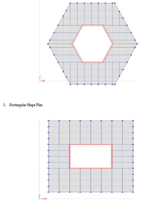
A. Building Plan
- Square shape plan
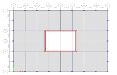
2. Hexagonal Shapes plan
V. RESULTS
Table 1.1 General Building Displacement Results Basic Wind Speed 39 M/Sec.
|
TABLE: Diaphragm Center of Mass Displacements |
|||||
|
Story |
Diaphragm |
Load Case/Combo |
UX |
UX |
UX |
|
mm |
mm |
mm |
|||
|
Story26 |
D1 |
WL+X |
11.898 |
13.817 |
10.374 |
|
Story25 |
D1 |
WL+X |
11.37 |
13.217 |
9.919 |
|
Story24 |
D1 |
WL+X |
10.833 |
12.605 |
9.455 |
|
Story23 |
D1 |
WL+X |
10.29 |
11.985 |
8.985 |
|
Story22 |
D1 |
WL+X |
9.739 |
11.355 |
8.508 |
|
Story21 |
D1 |
WL+X |
9.181 |
10.717 |
8.025 |
|
Story20 |
D1 |
WL+X |
8.617 |
10.07 |
7.536 |
|
Story19 |
D1 |
WL+X |
8.057 |
9.422 |
7.044 |
|
Story18 |
D1 |
WL+X |
7.493 |
8.766 |
6.549 |
|
Story17 |
D1 |
WL+X |
6.928 |
8.108 |
6.052 |
|
Story16 |
D1 |
WL+X |
6.364 |
7.45 |
5.556 |
|
Story15 |
D1 |
WL+X |
5.802 |
6.793 |
5.061 |
|
Story14 |
D1 |
WL+X |
5.249 |
6.153 |
4.583 |
|
Story13 |
D1 |
WL+X |
4.702 |
5.52 |
4.111 |
|
Story12 |
D1 |
WL+X |
4.167 |
4.899 |
3.649 |
|
Story11 |
D1 |
WL+X |
3.646 |
4.294 |
3.198 |
|
Story10 |
D1 |
WL+X |
3.143 |
3.708 |
2.763 |
|
Story9 |
D1 |
WL+X |
2.672 |
3.157 |
2.356 |
|
Story8 |
D1 |
WL+X |
2.223 |
2.631 |
1.967 |
|
Story7 |
D1 |
WL+X |
1.801 |
2.137 |
1.601 |
|
Story6 |
D1 |
WL+X |
1.411 |
1.678 |
1.262 |
|
Story5 |
D1 |
WL+X |
1.058 |
1.262 |
0.953 |
|
Story4 |
D1 |
WL+X |
0.752 |
0.899 |
0.684 |
|
Story3 |
D1 |
WL+X |
0.488 |
0.585 |
0.45 |
|
Story2 |
D1 |
WL+X |
0.27 |
0.326 |
0.255 |
|
Story1 |
D1 |
WL+X |
0.102 |
0.126 |
0.101 |
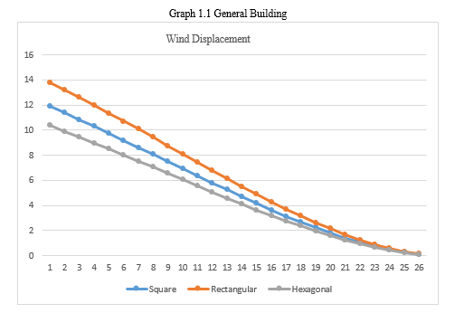
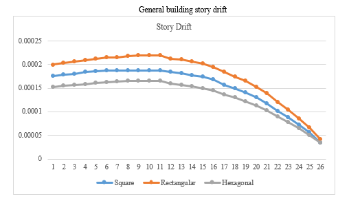
Table 1.2 General building story drift results basic wind speed 39 m/sec
|
TABLE: Story Drifts |
|||||
|
Story |
Load Case/Combo |
Direction |
Drift |
Drift |
Drift |
|
m |
m |
m |
|||
|
Story26 |
WL+X |
X |
0.000176 |
0.0002 |
0.000152 |
|
Story25 |
WL+X |
X |
0.000179 |
0.000204 |
0.000155 |
|
Story24 |
WL+X |
X |
0.000181 |
0.000207 |
0.000157 |
|
Story23 |
WL+X |
X |
0.000184 |
0.00021 |
0.000159 |
|
Story22 |
WL+X |
X |
0.000186 |
0.000213 |
0.000161 |
|
Story21 |
WL+X |
X |
0.000188 |
0.000216 |
0.000163 |
|
Story20 |
WL+X |
X |
0.000187 |
0.000216 |
0.000164 |
|
Story19 |
WL+X |
X |
0.000188 |
0.000218 |
0.000165 |
|
Story18 |
WL+X |
X |
0.000188 |
0.000219 |
0.000166 |
|
Story17 |
WL+X |
X |
0.000188 |
0.00022 |
0.000166 |
|
Story16 |
WL+X |
X |
0.000187 |
0.000219 |
0.000165 |
|
Story15 |
WL+X |
X |
0.000185 |
0.000213 |
0.00016 |
|
Story14 |
WL+X |
X |
0.000182 |
0.000211 |
0.000157 |
|
Story13 |
WL+X |
X |
0.000178 |
0.000207 |
0.000154 |
|
Story12 |
WL+X |
X |
0.000174 |
0.000202 |
0.00015 |
|
Story11 |
WL+X |
X |
0.000168 |
0.000195 |
0.000145 |
|
Story10 |
WL+X |
X |
0.000157 |
0.000184 |
0.000136 |
|
Story9 |
WL+X |
X |
0.00015 |
0.000175 |
0.00013 |
|
Story8 |
WL+X |
X |
0.000141 |
0.000165 |
0.000122 |
|
Story7 |
WL+X |
X |
0.00013 |
0.000153 |
0.000113 |
|
Story6 |
WL+X |
X |
0.000118 |
0.000139 |
0.000103 |
|
Story5 |
WL+X |
X |
0.000102 |
0.000121 |
0.00009 |
|
Story4 |
WL+X |
X |
0.000088 |
0.000105 |
0.000078 |
|
Story3 |
WL+X |
X |
0.000073 |
0.000086 |
0.000065 |
|
Story2 |
WL+X |
X |
0.000056 |
0.000067 |
0.000051 |
|
Story1 |
WL+X |
X |
0.000034 |
0.000042 |
0.000034 |
Bracing System In 39m/Sec Wind Speed
Table 5.3 wind displacement in bracing system in 39m/sec basic wind speed
|
TABLE: Diaphragm Center of Mass Displacements |
|||||
|
Story |
Diaphragm |
Load Case/Combo |
UX |
UX |
UX |
|
mm |
mm |
mm |
|||
|
Story26 |
D1 |
WL+X |
9.903 |
11.954 |
8.889 |
|
Story25 |
D1 |
WL+X |
9.488 |
11.459 |
8.518 |
|
Story24 |
D1 |
WL+X |
9.064 |
10.953 |
8.137 |
|
Story23 |
D1 |
WL+X |
8.632 |
10.437 |
7.75 |
|
Story22 |
D1 |
WL+X |
8.193 |
9.912 |
7.356 |
|
Story21 |
D1 |
WL+X |
7.746 |
9.378 |
6.956 |
|
Story20 |
D1 |
WL+X |
7.291 |
8.833 |
6.548 |
|
Story19 |
D1 |
WL+X |
6.836 |
8.284 |
6.137 |
|
Story18 |
D1 |
WL+X |
6.375 |
7.727 |
5.721 |
|
Story17 |
D1 |
WL+X |
5.912 |
7.165 |
5.301 |
|
Story16 |
D1 |
WL+X |
5.447 |
6.6 |
4.881 |
|
Story15 |
D1 |
WL+X |
4.981 |
6.034 |
4.46 |
|
Story14 |
D1 |
WL+X |
4.519 |
5.478 |
4.05 |
|
Story13 |
D1 |
WL+X |
4.062 |
4.928 |
3.643 |
|
Story12 |
D1 |
WL+X |
3.611 |
4.385 |
3.243 |
|
Story11 |
D1 |
WL+X |
3.17 |
3.853 |
2.851 |
|
Story10 |
D1 |
WL+X |
2.742 |
3.337 |
2.472 |
|
Story9 |
D1 |
WL+X |
2.338 |
2.848 |
2.113 |
|
Story8 |
D1 |
WL+X |
1.951 |
2.38 |
1.77 |
|
Story7 |
D1 |
WL+X |
1.587 |
1.937 |
1.446 |
|
Story6 |
D1 |
WL+X |
1.247 |
1.525 |
1.143 |
|
Story5 |
D1 |
WL+X |
0.938 |
1.149 |
0.866 |
|
Story4 |
D1 |
WL+X |
0.669 |
0.818 |
0.623 |
|
Story3 |
D1 |
WL+X |
0.435 |
0.532 |
0.411 |
|
Story2 |
D1 |
WL+X |
0.241 |
0.295 |
0.233 |
|
Story1 |
D1 |
WL+X |
0.092 |
0.112 |
0.092 |
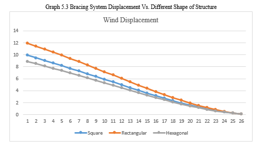
Table 5.4 story drift at bracing system in 39 m/sec basic wind speed
|
TABLE: Story Drifts |
|||||
|
Story |
Load Case/Combo |
Direction |
Drift |
Drift |
Drift |
|
m |
m |
m |
|||
|
Story26 |
WL+X |
X |
0.000138 |
0.000165 |
0.000124 |
|
Story25 |
WL+X |
X |
0.000141 |
0.000169 |
0.000127 |
|
Story24 |
WL+X |
X |
0.000144 |
0.000172 |
0.000129 |
|
Story23 |
WL+X |
X |
0.000146 |
0.000175 |
0.000131 |
|
Story22 |
WL+X |
X |
0.000149 |
0.000178 |
0.000134 |
|
Story21 |
WL+X |
X |
0.000152 |
0.000181 |
0.000136 |
|
Story20 |
WL+X |
X |
0.000152 |
0.000183 |
0.000138 |
|
Story19 |
WL+X |
X |
0.000153 |
0.000186 |
0.000139 |
|
Story18 |
WL+X |
X |
0.000154 |
0.000187 |
0.00014 |
|
Story17 |
WL+X |
X |
0.000155 |
0.000188 |
0.000141 |
|
Story16 |
WL+X |
X |
0.000155 |
0.000189 |
0.000141 |
|
Story15 |
WL+X |
X |
0.000154 |
0.000185 |
0.000137 |
|
Story14 |
WL+X |
X |
0.000153 |
0.000184 |
0.000136 |
|
Story13 |
WL+X |
X |
0.00015 |
0.000181 |
0.000134 |
|
Story12 |
WL+X |
X |
0.000147 |
0.000177 |
0.000131 |
|
Story11 |
WL+X |
X |
0.000143 |
0.000172 |
0.000127 |
|
Story10 |
WL+X |
X |
0.000135 |
0.000163 |
0.00012 |
|
Story9 |
WL+X |
X |
0.000129 |
0.000156 |
0.000114 |
|
Story8 |
WL+X |
X |
0.000122 |
0.000147 |
0.000108 |
|
Story7 |
WL+X |
X |
0.000113 |
0.000137 |
0.000101 |
|
Story6 |
WL+X |
X |
0.000103 |
0.000125 |
0.000093 |
|
Story5 |
WL+X |
X |
0.00009 |
0.00011 |
0.000081 |
|
Story4 |
WL+X |
X |
0.000078 |
0.000095 |
0.000071 |
|
Story3 |
WL+X |
X |
0.000065 |
0.000079 |
0.00006 |
|
Story2 |
WL+X |
X |
0.00005 |
0.000061 |
0.000047 |
|
Story1 |
WL+X |
X |
0.000031 |
0.000037 |
0.000031 |
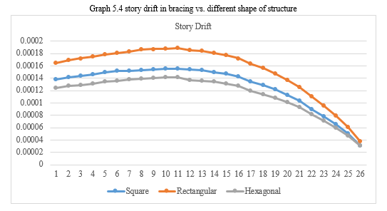
Table 1.5 Displacement Results in Open Story In 39 M/Sec Basic Wind Speed
|
TABLE: Diaphragm Center of Mass Displacements |
|||||
|
Story |
Diaphragm |
Load Case/Combo |
UX |
UX |
UX |
|
mm |
mm |
mm |
|||
|
Story26 |
D1 |
WL+X |
5.068 |
4.904 |
5.53 |
|
Story25 |
D1 |
WL+X |
4.847 |
4.695 |
5.292 |
|
Story24 |
D1 |
WL+X |
4.621 |
4.481 |
5.048 |
|
Story23 |
D1 |
WL+X |
4.391 |
4.263 |
4.799 |
|
Story22 |
D1 |
WL+X |
4.158 |
4.04 |
4.546 |
|
Story21 |
D1 |
WL+X |
3.92 |
3.814 |
4.289 |
|
Story20 |
D1 |
WL+X |
3.682 |
3.586 |
4.031 |
|
Story19 |
D1 |
WL+X |
3.445 |
3.358 |
3.771 |
|
Story18 |
D1 |
WL+X |
3.205 |
3.125 |
3.507 |
|
Story17 |
D1 |
WL+X |
2.964 |
2.891 |
3.242 |
|
Story16 |
D1 |
WL+X |
2.722 |
2.656 |
2.976 |
|
Story15 |
D1 |
WL+X |
2.483 |
2.423 |
2.713 |
|
Story14 |
D1 |
WL+X |
2.247 |
2.196 |
2.458 |
|
Story13 |
D1 |
WL+X |
2.014 |
1.971 |
2.206 |
|
Story12 |
D1 |
WL+X |
1.784 |
1.749 |
1.958 |
|
Story11 |
D1 |
WL+X |
1.561 |
1.532 |
1.715 |
|
Story10 |
D1 |
WL+X |
1.346 |
1.324 |
1.483 |
|
Story9 |
D1 |
WL+X |
1.144 |
1.127 |
1.265 |
|
Story8 |
D1 |
WL+X |
0.952 |
0.939 |
1.057 |
|
Story7 |
D1 |
WL+X |
0.771 |
0.762 |
0.86 |
|
Story6 |
D1 |
WL+X |
0.603 |
0.598 |
0.677 |
|
Story5 |
D1 |
WL+X |
0.452 |
0.449 |
0.512 |
|
Story4 |
D1 |
WL+X |
0.321 |
0.32 |
0.368 |
|
Story3 |
D1 |
WL+X |
0.208 |
0.208 |
0.243 |
|
Story2 |
D1 |
WL+X |
0.115 |
0.115 |
0.137 |
|
Story1 |
D1 |
WL+X |
0.043 |
0.044 |
0.054 |
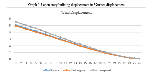
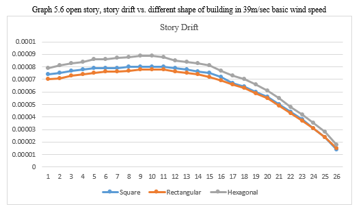
Table 5.6 open story drift vs. different shape of structure in 39m/sec
|
TABLE: Story Drifts |
|||||
|
Story |
Load Case/Combo |
Direction |
Drift |
Drift |
Drift |
|
m |
m |
m |
|||
|
Story26 |
WL+X |
X |
0.000074 |
0.00007 |
0.000079 |
|
Story25 |
WL+X |
X |
0.000075 |
0.000071 |
0.000081 |
|
Story24 |
WL+X |
X |
0.000077 |
0.000073 |
0.000083 |
|
Story23 |
WL+X |
X |
0.000078 |
0.000074 |
0.000084 |
|
Story22 |
WL+X |
X |
0.000079 |
0.000075 |
0.000086 |
|
Story21 |
WL+X |
X |
0.000079 |
0.000076 |
0.000086 |
|
Story20 |
WL+X |
X |
0.000079 |
0.000076 |
0.000087 |
|
Story19 |
WL+X |
X |
0.00008 |
0.000077 |
0.000088 |
|
Story18 |
WL+X |
X |
0.00008 |
0.000078 |
0.000089 |
|
Story17 |
WL+X |
X |
0.00008 |
0.000078 |
0.000089 |
|
Story16 |
WL+X |
X |
0.00008 |
0.000078 |
0.000088 |
|
Story15 |
WL+X |
X |
0.000079 |
0.000076 |
0.000085 |
|
Story14 |
WL+X |
X |
0.000078 |
0.000075 |
0.000084 |
|
Story13 |
WL+X |
X |
0.000076 |
0.000074 |
0.000083 |
|
Story12 |
WL+X |
X |
0.000075 |
0.000072 |
0.000081 |
|
Story11 |
WL+X |
X |
0.000072 |
0.000069 |
0.000077 |
|
Story10 |
WL+X |
X |
0.000067 |
0.000066 |
0.000073 |
|
Story9 |
WL+X |
X |
0.000064 |
0.000063 |
0.00007 |
|
Story8 |
WL+X |
X |
0.00006 |
0.000059 |
0.000066 |
|
Story7 |
WL+X |
X |
0.000056 |
0.000055 |
0.000061 |
|
Story6 |
WL+X |
X |
0.00005 |
0.000049 |
0.000055 |
|
Story5 |
WL+X |
X |
0.000044 |
0.000043 |
0.000048 |
|
Story4 |
WL+X |
X |
0.000038 |
0.000037 |
0.000042 |
|
Story3 |
WL+X |
X |
0.000031 |
0.000031 |
0.000035 |
|
Story2 |
WL+X |
X |
0.000024 |
0.000024 |
0.000028 |
|
Story1 |
WL+X |
X |
0.000014 |
0.000015 |
0.000018 |
Conclusion
A. Analysis of RCC tube in tube structure with different basic wind speed i.e., 39m/sec, and 55m/sec with medium soil condition at zone III has been done and significant variations in square building has been noted as compared to rectangular and hexagonal building. B. Results indicate that same all value similar to tube in tube with open story, because of earthquake zone are same for both type of building. C. Analysis of RCC tube in tube structure and tube in tube with open story structure in zone III with medium soil but overall performance of tube in tube with open story structure is healthier than remaining all structure. D. Comparing the displacement in tube in tube structure and tube in tube with open story structure almost both displacement results are same, but the wind displacement is increased as compare to 39m/sec basic wind speed but relatively shows good performance in time ages. E. The story drift in tube in tube structure and tube in tube with open story structure both structures are 4 to 4.5 % drift are available so structure behaviour are nonlinear. And also, in different shape structure 3 to 3.7 % drift are available, so structure is show linear behaviour. F. Also, Analysis of RCC different shape of tube in tube structure i.e. rectangular, Square and Hexagonal shape structure in basic wind speed 39m/sec with 55m/sec in medium soil but overall performance of square shape of structure is healthier than remining all shape of structure.
References
[1] Analysis Of RCC Tube in Tube Structure with Different Basic Wind Speed I.E., 39m/Sec, and 55m/Sec with Medium Soil Condition at Zone III Has Been Done. [2] Results Indicate That Same All Value Similar to Tube in Tube with Open Story, Because Of Earthquake Zone Are Same for Both Type of Building. [3] Analysis Of RCC Tube In Tube Structure And Tube In Tube With Open Story Structure In Zone III With Medium Soil But Overall Performance Of Tube In Tube With Open Story Structure Is Healthier Than Remaining All Structure. [4] Comparing The Wind Displacement In Tube In Tube Structure And Tube In Tube With Open Story Structure, In Wind Displacement Increased As Compare To 39m/Sec Basic Wind Speed But Relatively Shows Good Performance In Time Ages. [5] The Story Drift In Tube In Tube Structure And Tube In Tube With Open Story Structure Both Structures Are 4 To 4.5 % Drift Are Available So Structure Behaviour Are Nonlinear. And Also, In Different Shape Structure 3 To 3.7 % Drift Are Available, So Structure Is Show Linear Behaviour. [6] Also, Analysis of RCC Different Shape of Tube in Tube Structure I.E. Rectangular, Square and Hexagonal Shape Structure in Basic Wind Speed 39m/Sec With 55m/Sec in Medium Soil but Overall Performance of Square Shape of Structure Is Healthier Than Remining All Shape of Structure. [7] Imposed Loads”, Bureau of Indian Standards, New Delhi, 1987. IS 456, “Indian Standard Code of Practice for Plain and Reinforced Concrete”, Bureau of Indian Standards, New Delhi, 2000. IS 1893 (Part I), “Criteria For Earthquake Resistant Design Of Structures”, Bureau Of Indian Standards, New Delhi, 2002.
Copyright
Copyright © 2023 Abhishek Wadde, Dr. Uttam Awari. This is an open access article distributed under the Creative Commons Attribution License, which permits unrestricted use, distribution, and reproduction in any medium, provided the original work is properly cited.

Download Paper
Paper Id : IJRASET48468
Publish Date : 2022-12-30
ISSN : 2321-9653
Publisher Name : IJRASET
DOI Link : Click Here
 Submit Paper Online