

Ijraset Journal For Research in Applied Science and Engineering Technology
Wind Load Analysis on Different Configuration on Stadium Light Pole
Authors: M. Ramkumar, R. Ramakrishnan
DOI Link: https://doi.org/10.22214/ijraset.2022.43967
Certificate: View Certificate
Abstract
In this work, a comprehensive study is made in a dynamic manner to understand the effect of this corrosive induced structural failure of a monopile flood light tower. Various climatic conditions subjected to rural and urban environments are considered to understand the source of failure and these results are effectively utilized to optimize the design of these structures to increase their fatigue life in turn reduces the possibility of catastrophic failures. Computational fluid dynamics (CFD) and Finite element analysis (FEA) play a vital role in conceptual design and design for development in industries and research where pure mathematical and experimental approaches are next to impossible. Thanks to these technologies many insights are revealed during the design evolution of a product that helps in optimum design of a product. This work utilizes the surface chemical reaction capability that is available in Ansys Fluent to conduct a detailed aerodynamic study for various wind conditions and to locate the place of maximum corrosion and these inferences are in turn will be utilized in further FEA analysis to predict the structural failures.Finally these interpretations are applied in reaching an optimum monopile structure with design retro-fittings and design alterations that enhance the applicability of these structures.
Introduction
I. INTRODUCTION
The revolution of technological advancements in computers was known for the past two decades. Today, numerous advancements have been developed and the whole world solely depends on computers to perform the tasks. Heavy and complex functions are being executed by the computers and produce huge amounts of heat that will damage its own parts.Our project examines the problem which causes the damages and confronts the alternative and modification for the base model. We approach CFD to witness the exact problem that provides the best alternative rather than experimental methods where it costs high and will not produce instantaneous changes.
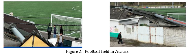
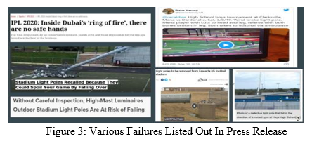
A. Flood Light Failures and Evidences
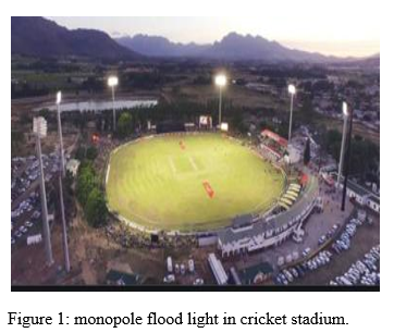
A floodlight is a broad-beamed, high-intensity artificial light. They are often used to illuminate outdoor playing fields while an outdoor sports event is being held during low-light conditions. More focused kinds are often used as a stage lighting instrument in live performances such as concerts and plays. The monopile support structure is a simple design by which the tower is supported by the monopile, either directly or through a transition piece, which is a transitional section between the tower and the monopile. The monopile continues down into the soil. The structure is made of cylindrical steel tubes .
II. LITERATURE REVIEW
- ”An Investigation of Wind Load Effect on a Light Pole Structure with Stiffener Using ANSYS”. Fousi M.S, Chaithra .S
? In hexagonal poles with FRP the stress increases is 16.4% when compared to circular pole with FRP.
? Increase of 20.55% on deformation in hexagonal pole FRP compared to circular pole with FRP. When stiffener is placed deformation decrease because stiffener bears the stress
2. “Design analysis and commissioning of high mast lighting poles”. Syed Ibrahim Dilawer, MD. Abdul Raheem Junaidi, Dr.S. Nawazish Mehdi, G.M.Sayeed Ahmed
- This paper illustrates the theoretical basis and the analytical development of high mast lighting poles. This paper clarified the deformation ratio via stress and strain relationship at top and bottom portion
3. “Parametric Study of Fatigue In Light Pole Structures”. Maryam Sadat Hosseini
- Many of these failures are caused by wind-induced vibration, resulting in various applied stress cycles at the weld toe. This analyzed the application of wind forces and specifically wind-gusts at the weld toes of light pole structures. Predicting fatigue life, damage, stress and strain.
4. “A Study On Wind Induced Vibration On Lighting Poles”. Suma Devi , L Govindaraju
- Single luminaire poles are more susceptible to any type of wind excitations compared to Double luminaire poles. The UBC 97 Code has shown the least variation in the performance of single and double luminaire poles for both wind with gust and without gust cases.
5. ”Aeroelastic wind tunnel test of a high lighting pole”. Yaozhi Luo, Yucheng Wang, JimingXie, Chao Yang and Yanfeng Zheng
- Uneven mass distribution, the wind effect concentrated more on lamp part, thus the connection between the lampshade and the pole and the middle part of lampshade will subjected to larger bending moment and shear force while the first order and sec
6. ”Failure analysis of a high mast lamp post”. G. Das , S. Chakrabarty, A.K. Dutta, S.K. Das, K.K. Gupta, R.N. Ghosh.
7. “CFD Analysis of Natural Ventilation Behavior in Four Sided Wind Catcher”, World Academy of Science, Engineering and Technology 72 2012, At penang, Malaysia
- This paper presents a series of 3D steady RANS simulations for a generic isolated four-sided wind catcher attached to a room subjected to wind direction ranging from 0º to 180º with an interval of 45º.
III. PROBLEM DEFINITION
To find the structural failure of the stadium light pole using Ansys - Finite Element Analysis (FEA) with various cross sections, shapes, materials, and atmospheric boundary layer conditions. The efficient and safe light pole design configuration will be recommended.
A. Computational Fluid Dynamics
Computational Fluid Dynamics (CFD) is the science of predicting fluid flow, heat transfer, mass transfer, chemical reactions, and related phenomena by solving the mathematical equations which govern these processes using a numerical process.
B. Why Computational Fluid Dynamics?
To analyze ,understand and to optimize fluid flow problems that are associated with Turbulence, Heat-Transfer, Species-Transport, Chemical Kinetics we have the following three modes of examination
- Experimental Investigation
- Mathematical Modeling and
- Numerical or Computational Modeling.
C. Computational Methods
- The differential quotients present in the mathematical equations are converted in to difference quotients
- The discretized form of equations are solved in millions of nodal points to obtain piecewise continuous set of solutions
- It involves three major activities namely pre-processing, solver and post-processing,
- Pre-processing involves geometry domain, type of flow, define the computational domain and check for predominant flow direction and Mesh generation (decompose into cells or elements).
- Solver involves selecting the suitable flow model, input parameters like velocity, temperature, pressure, fluid properties etc. (i.e., information about the main flow regime). Iterations (calculations have been run and to check convergence principles).
- Finally, Post-Processing is important to check the residuals, relative solution changes, and contours to make sure that iterations converge. Solution of derived quantities like stream functions, vortices, etc. Also solution parameters like lift, drag, total mass or Mass-Weighted Average etc., 3D information (cut-lines, cut-plates, iso-surfaces, iso-volumes).
IV. METHODOLOGY
The focus of this project is to analyze the effects of wind forces, wind gusts and wind-induced vibration on the monopile structure and observe the critical stresses, as well as the fatigue life of the monopile by utilizing Computational fluid dynamics and finite element method.
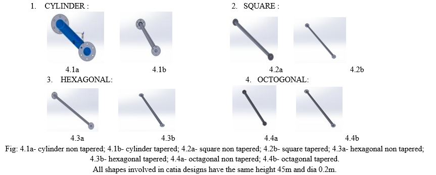
A. CATIA Designs
Shapes involved in Analysis:
B. CFD Processing
- Solver Setup
- Ansys CFX is utilized to solve this case
- Air is assumed to be continuum fluid
- Rain is assumed in discrete phase and 3000 particle is assumed for our Fluid domain area
- Velocity inlet boundary condition is imposed at air inlet boundary with 1 atmosphere (Total pressure)
- Velocity inlet boundary condition is imposed at rain water boundary with 1 atmosphere (Total pressure)
- Walls are assumed to be adiabatic with no slip condition
- SIMPLE algorithm is used to solve the problem
- Segregated solver is used for pressure-velocity coupling.
Boundary conditions
- Air Inlet – 1 m/s&Rain Inlet – 1.2 m/s
- Outlet Pstatic=0
- Outer Boundary – Symmetry
Cell zone conditions:
The working fluid in the domain is composed of air & Water.
|
Properties/Material |
Symbols |
Air (Fluid) |
Water (Fluid) |
|
Density (kg/m3) |
ρ |
incompressible-ideal-gas |
998.2 |
|
Specific Heat (j/kg-K) |
Cp |
1006.43 |
4182 |
|
Thermal Conductivity (w/m-k) |
k |
0.0242 |
0.6 |
|
Viscosity (kg/m-s) |
μ |
Sutherland assumption |
0.001003 |
Table1 : represents the working fluid domain.
2. Cylinder
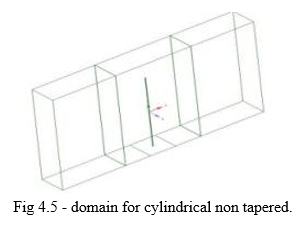
- Very fine mesh is used for high accuracy.
- Hex mesh is created in the domain to increase the result accuracy
- Due to the complexity in geometry, it is impossible to create hex mesh near wall, so we have created tet mesh
- Different types of elements like tri, quad are appropriately used in defining conformal interfaces which facilitate good quality of mesh
- Geometry is discretized with tri elements .Fine elements are used to capture the geometrical features more accurately.
- Volume mesh - 4051242
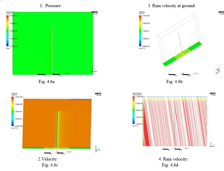
Fig:4.6a and 4.6c The air flowing in xy direction so there are formation of wake due to formation wake the air velocity is significantly reduced regions behind the geometry.Fig:4.6b and 4.6d In this contour the rain velocity is shown in ground of 1 m2 area. Here the wet area is maximum in the frontal area and minimal in the rear side due to formation of the wake region.
3. Cylinder Taper
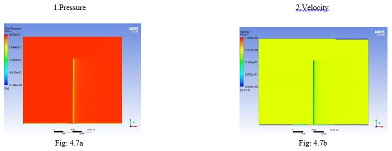
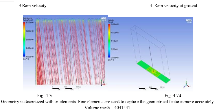
Fig: 4.7a and 4.7b represents the air flowing in xy direction so there are formation of wake due to formation wake the air .velocity is significantly reduced regions behind the geometry.In this geometry their slight difference in formation of wake region due to tapered geometry . Fig: 4.7c and 4.7d represents In this contour the rain velocity is shown in ground of 1 m2 area. Here the wet area is maximum in the frontal area and minimal in the rear side due to formation of the wake region. Due to tapered region, there is marginal decrease in rain velocity water in ground.
4. Hexagonal
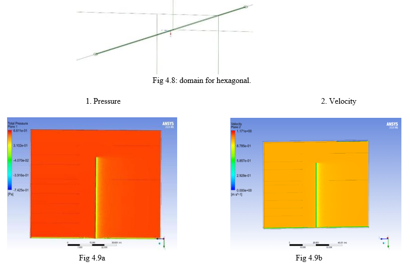
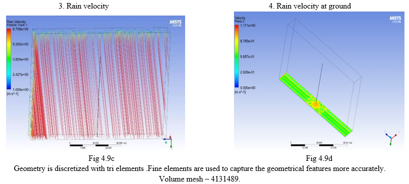
Fig 4.9a and 4.9b represent the air is flowing in the xy direction, there is the development of wake, and the air velocity is greatly reduced in the regions behind the geometry.There are no significant differences in wake region when compared with above geometrical configuration. Fig 4.9c and 4.9d In this contour the rain velocity is shown in ground of 1 m2 area.Here the wet area is maximum in the frontal area and minimal in rear side due to formation of wake region.
5. Hexagonal Taper
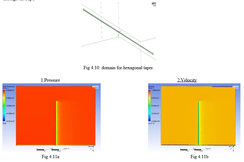
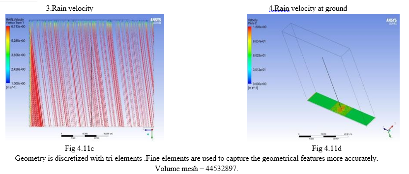
Fig 4.11a and 4.11b, In this geometry there is a slight difference in formation of the wake region due to tapered geometry. But there is no significant difference when compared with cylinder taper. Fig 4.11c and 4.11d, Due to the creation of a wake zone, the wet area is greatest in the frontal area and least in the rear. Rain velocity in the ground is somewhat reduced due to the tapering area. But there is no significant difference when compared with cylinder taper.
8. Octogonal
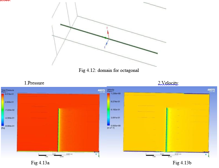
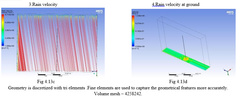
Fig 4.13a and 4.13b, because the air is flowing in the xy direction, there is the development of wake, and the air velocity is greatly reduced in the regions behind the geometry. There are no significant differences in wake region when compared with above geometrical configuration. Fig 4.13c and 4.13d, This contour depicts the rain velocity in a 1 m2 patch of ground.
Due to the creation of a wake zone, the wet area is greatest in the frontal area and least in the rear.
Rain velocity has intensified somewhat near the wall.
7. Octogonal Taper
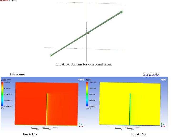
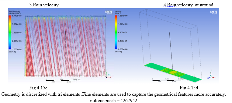
Fig 4.15a and 4.15b, Because the air is flowing in the xy direction, there is the development of wake, and the air velocity is greatly reduced in the regions behind the geometry. There are no significant differences in wake region when compared with above geometrical configuration. Fig 4.15c and 4.15d, This contour depicts the rain velocity in a 1 m2 patch of ground.
Due to the creation of a wake zone, the wet area is greatest in the frontal area and least in the rear.
Rain velocity is very minimal when compared to all other geometrical configurations somewhat near the wall.
8. Square
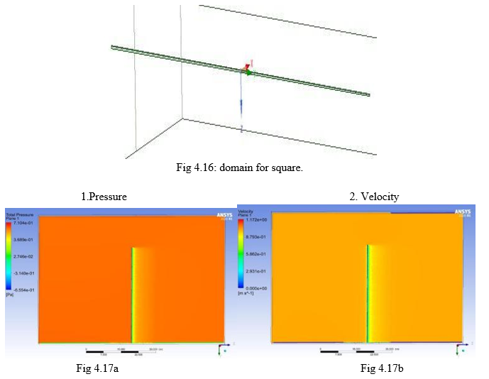
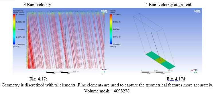
Fig 4.17a and 4.17b, because the air is flowing in the xy direction, there is the development of wake, and the air velocity is greatly reduced in the regions behind the geometry. There are no significant differences in wake region when compared with above geometrical configuration. Fig 4.17c and 4.17d, This contour depicts the rain velocity in a 1 m2 patch of ground.
Due to the creation of a wake zone, the wet area is greatest in the frontal area and least in the rear.
Rain velocity has intensified somewhat near the wall and less in the outer region.
9. Square Taper
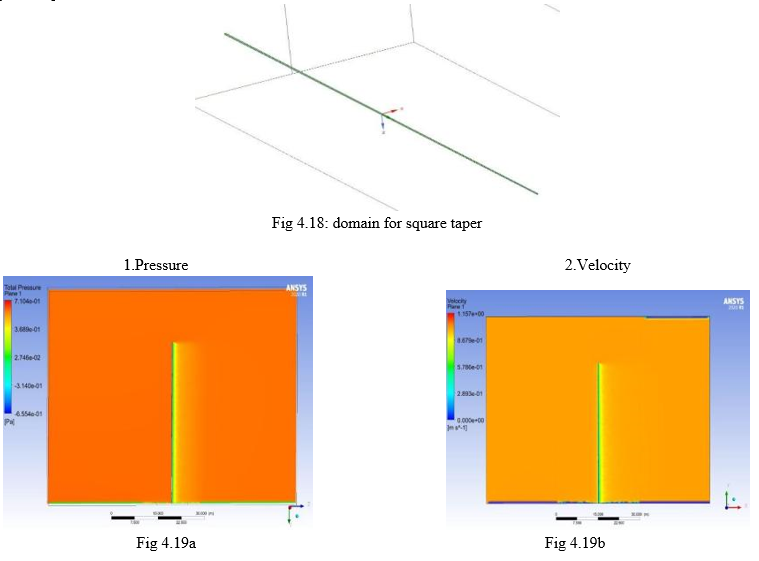
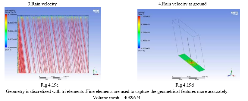
Fig 4.19a and 4.19b, The rain velocity in a 1 m2 patch of ground is depicted in this contour. Because of the creation of a wake zone, the wet area is greatest in the front and least in the back. Rain velocity is somewhat higher near the wall. Fig 4.19c and 4.19d, The wet area is highest in the frontal area and least in the rear due to the establishment of a wake zone. When compared to all other geometrical configurations near the wall, rain velocity is great. As a result, we can deduce that square tapered will corrode more than the other geometries investigated in this study.
V. RESULTS AND DISCUSSIONS
A. Mesh Results
|
Parameter |
Cylinder |
Cylinder Taper |
Hex |
Hex Taper |
Oct |
Oct Taper |
Square |
Square Taper |
|
Volume Mesh Count |
5051242 |
5141541 |
5131489 |
44532897 |
4958242
|
4867942 |
5098278
|
5189674
|
|
Volume mesh quality |
0.89 |
0.89 |
0.89 |
0.88 |
0.89 |
0.89 |
0.89 |
0.89 |
Table 2: fine mesh values for shapes.
|
Geometrical Configuration |
Rain averaged volume fraction (PPM) |
|
Cylinder |
500.012 |
|
Cylinder Taper |
499.756 |
|
Hexagonal |
514.17 |
|
Hexagonal Taper |
518.03 |
|
Octagonal |
409.256 |
|
Octagonal Taper |
526.172 |
|
Square |
515.269 |
|
Square Taper |
618.1164 |
Conclusion
1) Various geometrical configurations such as cylinder; hexagonal, octagonal and square and their respective taper are analyzed and variables such as total pressure; rain velocity and rain averaged volume fraction; have been analyzed in the project. 2) From the results of all configurations, we conclude that square tapered have high rain averaged volume fraction compared with other geometrical configurations. 3) Thus, we can conclude that square tapered will have more corrosion reaction than other models 4) On the other hand, comparing the results of all configurations, we conclude that Octagonal rain averaged volume fraction compared with other geometrical configurations. 5) Thus, we can conclude that Octagonal will have less corrosion reaction than other models.From the above CFD analysis, the corrosion effect on different cross sections were listed with the effect of wind gust and rain effect on the place of the light pole. It shows that the monopole , where we are fixed to be having both extreme conditions namely sudden wind and rain impact, here by using CFD ansys FLUENT , I am suggesting the least corrosion resistance and high corrosion resistance . From the above discussions octagonal taper monopoles have less corrosion resistance than other cross sections.
References
[1] Aragon-Gonzalez, G. Canales-Palma, A. Leon-Galicia, A and Morales-Gomez, J.R (2008). “Maximum power, ecological function and efficiency of an irreversible Carnot cycle. A cost and effectiveness optimization”. Brazilian Journal of Physics 38(4), 543-550. [2] Kamil, M. et al (2014). “An Integrated Model for Predicting Engine Friction Losses in Internal Combustion Engines”. International Journal of Automotive and Mechanical Engineering 9, 1695-1708 [3] Lingen Chen, Shaojun Xia and Fengrui Sun (2011). “Optimizing piston velocity profile for maximum work output from a generalized radiative law Diesel engine”. Mathematical and Computer Modelling 54, 2051-2063. [4] Lingen Chen, Shaojun Xia, and Fengrui Sun (2009). “Optimal paths for minimizing entropy generation during heat transfer processes with a generalized heat transfer law”. Journal of Applied Physics 105, 044907-1-5. [5] Morton, H. Rubin (1979). “Optimal configuration of a class of irreversible heat engines”. II. Physical Review A 19, 1277-1289. [6] Prasad, B.V.V.S.U. Sharma, C.S. Anand, T.N.C and R.V. Ravikrishna (2011). “High swirl-inducing piston bowls in small diesel engines for emission reduction”. Applied Energy 88, 2355–2367. [7] Qi, K. Feng, L. Leng, X. Du, B and Long W (2011). “Simulation of quasi-dimensional combustion model for predicting diesel engine performance”. Applied Mathematical modelling 35(2), 930-940. [8] Payri, F. Benajes, J. Margot, X and Gil, A (2004). “CFD modeling of the in-cylinder flow in direct injection diesel engines”. Computer & Fluids 33, 995-1021. [9] Teh, K.Y. Edwards, C.F (2006). “An Optimal Control Approach to Minimizing Entropy Generation in an Adiabatic IC Engine with Fixed Compression Ratio”. in: Proceedings of IMECE2006, IMECE2006-13581, 2006 ASME International Mechanical Engineering Congress and Exposition, Chicago, Illinois, USA.. [10] Teh, K.Y. Edwards, C.F. (2006). “Optimizing piston velocity profile for maximum work output from an IC engine”, in: Proceedings of IMECE2006, IMECE2006-13622, 2006 ASME International Mechanical Engineering Congress and Exposition, Chicago, Illinois, USA. [11] Xia, S. Chen, L and Sun, F (2009). “The optimal path of piston motion for Otto cycle with linear phenomenological heat transfer law”. Science in China Series G: Physics, Mechanics & Astronomy 52 (5), 708-719.
Copyright
Copyright © 2022 M. Ramkumar, R. Ramakrishnan. This is an open access article distributed under the Creative Commons Attribution License, which permits unrestricted use, distribution, and reproduction in any medium, provided the original work is properly cited.

Download Paper
Paper Id : IJRASET43967
Publish Date : 2022-06-08
ISSN : 2321-9653
Publisher Name : IJRASET
DOI Link : Click Here
 Submit Paper Online