

Ijraset Journal For Research in Applied Science and Engineering Technology
Comparative Study of Balance Cantilever Bridge and Extradosed Bridge
Authors: Shriket P. Rajeshirke, Prof. Yogesh R. Suryawanshi, Prof. Dr. Navnath V. Khadake
DOI Link: https://doi.org/10.22214/ijraset.2022.43126
Certificate: View Certificate
Abstract
Now a days, in India Balance Cantilever bridges are widely used in hilly region were supporting from the bottom is difficult. The name Balance Cantilever Bridge is arrived due to the application of construction methodology which balances out the cantilever portion. It is one of the most effective methods of building bridges without the need of false work. Balanced cantilever bridges are used for special requirements like construction over traffic, short lead time compared to steel and use local labour and materials. Extradosed bridge is a unique idea bridge between Girder Bridge and cable-stayed bridge. A balanced cantilever bridge with construction stage analysis consideration a model is prepared in the Midas Civil software and analysed, we can see how it considers construction stage analysis with creep & shrinkage effect. The construction stage analysis in the Midas Civil considers shrinkage and creep during construction stages to simulate the construction process of a incremental stage. As most of the literature covers either balance cantilever bridge or extradosed bridge, this paper introduces and attempt to summaries comparative study of balance cantilever and extra dose bridge with its span arrangement, span by depth ratio, prestressing steel etc.
Introduction
I. INTRODUCTION
Mathivat Jacques is France engineer who is recognized as the inventor of extradosed bridge type. According to Mathivat in recent new type bridges which are implemented to Cable stayed Bridges from traditional post tensioned balance cantilever bridges. Extradosed Bridge are combination of posttensioned balance cantilever bridge and cable stayed bridge. Conventional post tensioned balance cantilever bridges and cable stayed bridges have their own specific structural behaviour like construction methodology, stay cable arrangement, economic advantages and span limitation. For conventional balance cantilever bridges economical span ranges between 50m to 150m and on other side for cable stayed bridge span ranges above 200m. Now a day economical span ranges are now increased due to advancement in construction material, design and construction methodology. It is suggested that economical span ranges for Extradosed bridge is between 75 m to 250 m . Cantilevering construction method for a long span bridge either post-tensioned box girder balanced cantilever method bridges or cable stayed bridge is still the dominance construction method.
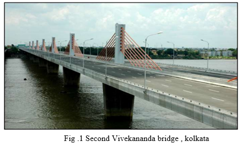
First extradosed bridge was built in India by Larsen & Toubro Ltd. It called the Second Vivekananda Bridge fig. 1 over river Hooghly, Kolkata. This bridge is 880 meters long, and having a span of 110 meters. A new bridge is constructed in 2017 across Narmada River in Bharuch. This was the first "extradosed bridge" to be built in Gujarat and the "longest" in the country.
II. THEORY
A. Balance Cantilever
A cantilever is a horizontal beam with a fixed support at one of its ends this two-dimensional graphical model of the structural system a horizontal line depicts the longitudinal axis of the beam. For simple calculation of the beam deflection under load one needs to know the beam length, its modulus of elasticity as a material parameter, and the moment of inertia of the beam cross-section need to be known. Loads on the beam can occur in form of loads and moments that can be singular or distributed over the beam length in a uniform or variable manner.
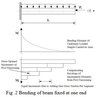
When structural analysis is performed on a cantilever system, Figure 2 shows the modelling approach which is used in construction stages separately and are finally superposed to come up with the overall structural behaviour. Taking the example of a free cantilever of continuous cross-section that is composed of segments with different ages and is held together with prestressing tendons, the cantilever system is loaded through its own dead load and an anticipated uniform live load under service, which will in turn create the well-known parabolic moment curve for a cantilever beam.
Post tensioning tendons are used within the cantilever beam to compensate for the dead load moment, for simplification it shall be assumed that the prestressing tendons that are added with every new segment are all located at the same eccentricity from the neutral axis of the cantilever beam cross-section. Assuming further that all tendons are straight without curvature (as would be used in real bridge structures), the superposition of the moments from all post-tensioning tendons provides a cumulative moment effect that compensates the dead load moment. Two parameters are need to be determine as long-term stresses ( serviceability case ) and deformations of the structural system based on time-dependent material properties, i.e. creep and shrinkage of concrete and relaxation. This is called end of construction stage analysis (EOC) and the assumed ‘infinity’, frequently chosen to be day 10,000 after beginning construction. Before end of construction the cantilever system of the bridge changes to a continuous girder system by changing its support condition. Moment redistribution from supports towards the spans takes place. Different ages of segment play a role when determining stresses and deformations of the structural system in construction stages and at the end of construction.
Cantilever construction consists in building a bridge deck by a succession of segments, where each segment placed carries the weight of the next segment and, on occasion the weight of the formwork , form traveller etc.
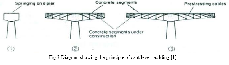
Each section or segment is integrated with the previous one as soon as it is strong enough; it then become self-supporting and, in its turn, is the starting base for a new segment. The stability of the resulting cantilever is secure, at each step of construction, by prestress cable which increase in length, and which are set in the upper fibers of the beam. The segments maybe concreted in situ in mobile forms. they can also be prefabricated transported and set into place with the appropriate lifting device The cantilevers are usually constructed in 3- to 6-m-long segments. Balanced cantilever construction method, negative bending moment during construction is the primary forces, the structural engineer must overcome primarily by cantilever tendons as shown in Figure 3.
The balanced cantilever bridge has its own drawbacks, since the longer the span the dead loads become larger and exorbitant to build. To increase the bending moment capacity at the superstructure, one should increase the number of cantilever tendons or eccentricity by increasing structural depth. There is difficulty to add more tendons in superstructure as there is less space available in top flange of box girder.
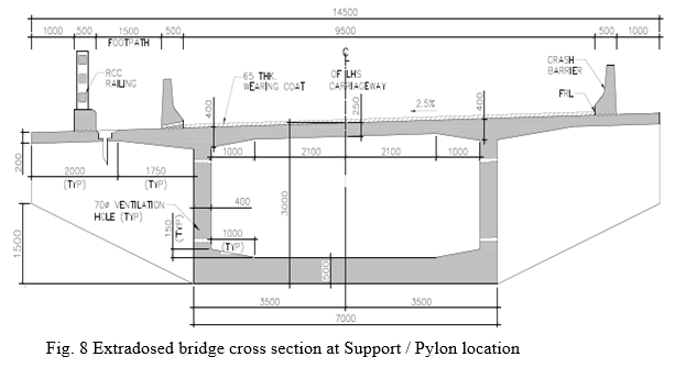
B. Extradosed Bridge
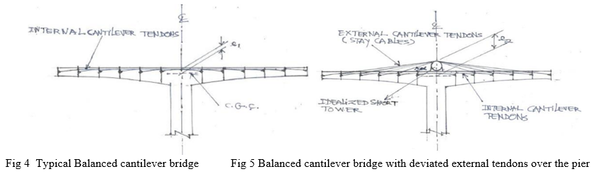
Extradosed bridge is a bridge is unique concept which has a similar structural behaviour and methodology that associate both of a balanced cantilever bridge and a cable stayed bridge. Mathivat saw the opportunity to increase bending moment and shear capacity by partially deviating some of the cantilever tendons over the pier (critical moment and shear) above the top flange to become external tendons supported by short deviator/tower as shown in Fig. 4. This excellent solution is able to take the advantages of internal tendons and external tendons with larger eccentricity. This results the reduction of cantilever top tendons in longer span.. As can be observed in Fig. 4 and 5, the tendon eccentricity e2 >> e1.
- Structural Behaviour and Analysis: Extradosed Bridges are highly redundant structures; their structural behavior varies with the relative stiffness of the deck, pylon, and cable system.In extradosed bridge , the superstructure consist higher stiffness than cable stay bridge therefore it allows live loads to be transferred to piers mainly in bending of the deck girder. This results in little activation of the cables under live loading and thus a corresponding small stress variation range. Hence, with regard to vertical loading, the cables in an extradosed bridge are designed to carry predominantly dead loads from the deck.
- Deck: Generally Extradosed Bridges have a concrete deck. However, it can be made of steel, or composite steel– concrete (Riga Southern Bridge in Latvia, Himi Bridge33 in Japan with corrugated steel webs). As with cable-stayed bridges, the longer the span, the more advantageous it is to reduce the self-weight of the deck by using steel instead of concrete. Therefore, concrete is generally used up to 180 m span. For spans longer than 200 m, composite or steel may be used in centre span.
Two cross sections are used
a. Decks with lateral beams or slab decks (only if there are lateral extradosed cables, in order to provide sufficient torsional stiffness).
b. Box-girders with horizontal or central extradosed cables
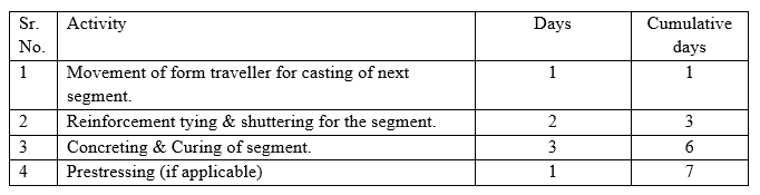
3. Pylon: Pylons are generally vertical. Pylon located at the edge of the deck, could be inclined outwards for aesthetic reasons. If extradosed cables are transversally inclined, then it produces a transverse tension in the deck, which must be considered for the transverse design of deck. The pylon transverse inclination can be extended to the form of the pier below the deck, again in order to improve the aesthetics of the bridge. The ratio of pylon height to main span length can vary between 1/15 and 1/8, but is most typically between 1/12 and 1/10.
4. Connection between Deck and Pier: There are many possibilities: pylon monolithic with pier but deck on bearings, a monolithic pylon-deck on bearings at the pier, and pylon-deck-pier monolithic. In the case of an Extradosed Bridge with a single pylon located longitudinally on one pier, it is preferable to make the deck girder, the pylon and the pier integral, making this location the point of longitudinal fixity for the bridge. In the case where bearings are provided between the deck girder and the pier, it is possible to use two rows of bearings in order to transfer longitudinal bending moment to the pier and at the same time allow longitudinal displacement of the deck with longitudinally sliding bearings.
III. PROBLEM STATEMENT
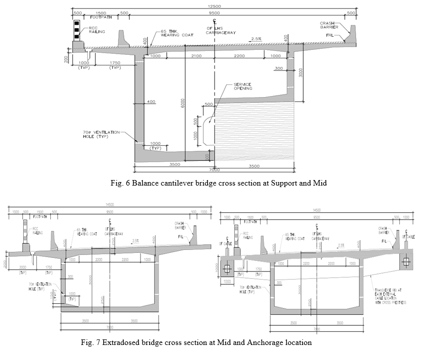
Single cell box girder is to analyze in construction stage and after completion of construction stage , stress check for serviceability condition for balance cantilever bridge and extradosed bridge with parameters as follows with the help of MIDAS civil.
A. Structural Data
- Span : 100 m
- Width of Deck Structure : 12.5m ,
- Width of Carriageway : 9.5m
- No of Lanes : 3 lane of class A or 70 R + Class A or SP Vehicle , Whichever is critical
- Type of Super Structure : balance cantilever & extra dosed are as follows.
IV. METHODOLOGY
This example has been simplified from an actual project for the purpose of illustrating construction stage analysis using Free Cantilever Method (FCM), The superstructure modelled as resting on bearing, As we need to compare the 100 m of span for balance cantilever and extradosed bridge , Normally cantilever bridges are design with monolithic pier as avoiding the complications of bearing shifting and replacement. But in our case , superstructure resting on bearing consideration gives independent distribution of bending moment. Ie. Bending moment of superstructure does not depend upon the Pier height , Pier thickness etc. The box section dimensions are calculated in excel spreadsheet.
The bridge profile is defined as follows,
Bridge type: 3-span continuous PSC Box Girder Bridge
Bridge length:
For Balance cantilever L = 55 + 100 +55 = 210 m
For Extradosed bridge L = 55 + 100 + 55 = 210 m ,
Bridge width: 12.5 M , Skew: 0° (No skew)
- Loading on Structure
Loading considered as per IRC 6: 2017
• Self weight of Box Girder
• Superimposed dead loads due to Footpath dead load, Footpath live load, Wearing coat and crash barrier etc.
• Moving loads as per IRC- 6
Class-A vehicle – 1 Lane or Class A vehicle – 2 Lane or Class A vehicle – 3 Lane or
Class 70 R + 1 Lane of class A or SP vehicle , whichever is critical.
• Impact of vehicular live load ( 1.088 )
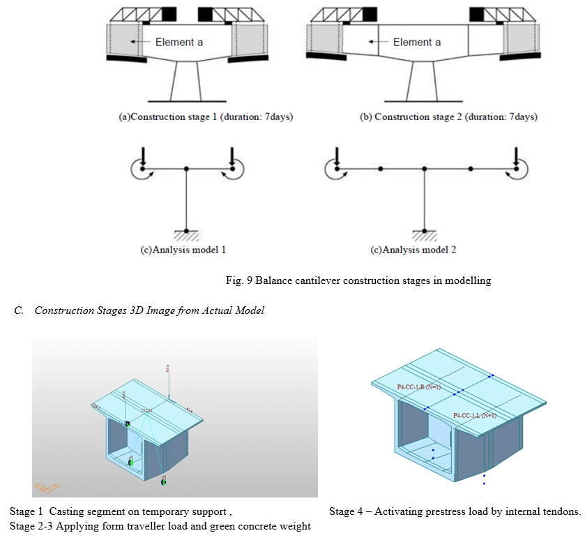
2. Construction stage Loading
- As the PSC Box superstructure is cast-in-situ, wet concrete load is considered when the concrete is poured for the next segment. A nodal load & nodal moment is applied at the tip of previously erected segment to simulate the wet concrete loads. The wet concrete loads are calculated using the density as 2.6 t/m3.
- The self weight of gantries required for casting of segment is considered as a part of construction stage load. A nodal load of 60 tons is considered to account for the self weight of gantry during construction stages. Also, as the gantry will be placed at an eccentricity from already casted girder, an additional moment will also be developed & hence a nodal moment of 69 t-m is considered during construction stage analysis.
3. Material Specification
Grade of Concrete for Girder = 50 Mpa
Density of wearing coat = 2.2 t/m3
Grade of reinforcement steel , Fyk = 500 Mpa
Prestressing anchorage system = 19 DP 13 , Diameter of Strand = 12.70 mm for internal cable
Nominal outer diameter of duct, Ø = 98mm
Class of Strand = 2
Type of Strand = IS 14268
Ultimate Tensile Load of Strand = 18737.0 kg
Nos. of strands in one cable = 19
U.T.S of Cable = 356.00 mton
Area of one strand = 98.70 mm2, Area of one Cable = 18.753 cm2
Prestressing anchorage system = 27 DP 15 , Diameter of Strand =15.20 mm for Stay cable
Nominal outer diameter of duct, Ø = 150mm
Nos. of strands in one cable = 27
U.T.S of Cable = 356.00 mton , Area of one strand =140 mm2 , Area of one Cable = 37.8 cm2
The methodology of balance cantilever bridge and extradosed bridge is as follows.
- Modelling of balance cantilever bridge and extradosed bridge as 3-D element in MIDAS Civil software by defining nodes and elements.
- Assigning section properties and materials to elements based on criteria and as per IRC 112.
- Calculation of dead load, Wearing coat , SIDL , form traveller load & vehicular live loading as per IRC 6: 2017.
- Assigning the Internal tendons.
- Application of loading.
- Defining construction stage as per site constraint and sequence.
- Analysing the model and extracting results
- Verifying the results with existing data and comparison of prestressing steel & other parameter.
A. Construction Stage Analysis
A bridge structure such as a segmental bridge, cable stayed bridge or PSC (prestressed or post-tensioned concrete) bridge requires construction stages to build and yet inter-related analyses for the completed structure and temporary structures during the construction.
Each temporary structure has some construction effects which is transfer on the permanent structure. Also, it is not uncommon to install and dismantle temporary supports and cables during construction.
The structure frequently changes or develops as the construction progresses with varying material properties such as modulus of elasticity, creep and compressive strength due to different maturities among adjoining members.
The structural behaviours such as deflections, rotation and stress re-distribution persist to change during and after the construction due to different time dependent properties such as concrete creep, shrinkage, modulus of elasticity (aging) and tendon relaxation. Since the structural configuration continuously changes with different loading and support conditions, and each construction stage affects the subsequent stages, the design of certain structural components may be governed during the construction.
Accordingly, the time dependent construction stage analysis is required to examine each stage of the construction and without such analysis the analysis for the final stage alone will not be reliable. In the program the following parameters are considered as Time dependent material properties during the construction stage,
- Creep effects of concrete members having different maturities
- Shrinkage effects of concrete members having different maturities
- Time dependent compressive strength gain for concrete members
- Prestressing tendon relaxation
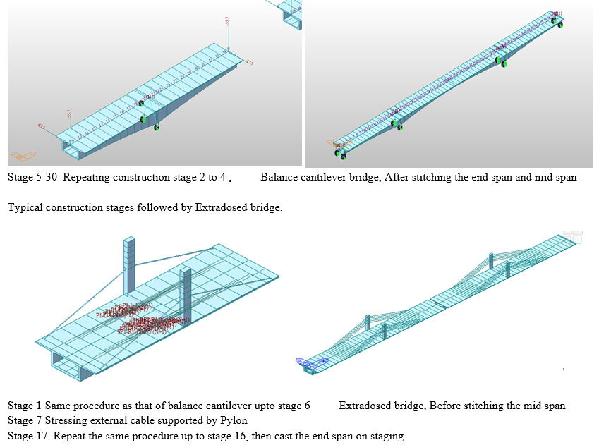
B. Typical Construction Cycle
The typical construction cycle of 7 days is considered in the construction stage analysis.

 ???????
Conclusion
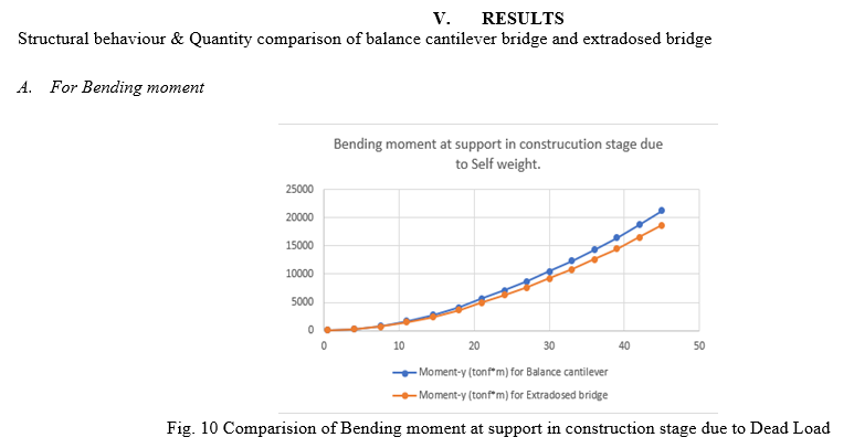
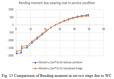
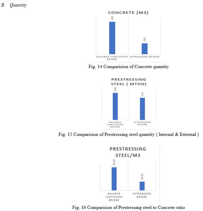
After the comparison of 100 m span of Balance cantilever bridge & extradosed bridge, it is concluded that: 1) The Maximum Bending moment due to self weight in construction stage is decreased by 12% in extradosed bridge as compared to balance cantilever. 2) The Maximum Bending moment due to prestress in construction stage is increased by 10% in extradosed bridge as compared to balance cantilever. 3) The Maximum Bending moment due to Superimposed dead load ( SIDL ) in construction stage is decreased by 8% in extradosed bridge as compared to balance cantilever. 4) The Maximum Bending moment due to Wearing coat (WC) in construction stage is decreased by 8% in extradosed bridge as compared to balance cantilever. 5) The concrete quantity is marginally decreased by 3-4% in extradosed bridge as compared to balance cantilever. 6) The Prestressing steel in extradosed bridge is decreased by 18% than balance cantilever. 7) The Prestressing steel to concrete ratio in extradosed bridge is decreased by 17% than balance cantilever. Overall from above points we can conclude that Extradosed bridge is more economical in respect of quantity of steel but it required special equipment to construct pylon and anchor the cable which need to be considered, although Extradosed bridge gives more aesthetical pleasing option than balance cantilever.
References
[1] Mathivat, J. (1988). “Recent developments in prestressed concrete bridges”. FIP Notes, 2, 15-2 [2] José Benjumea , Gustavo Chio, Esperanza Maldonado (2010) ,\" Structural behavior and design criteria of extradosed bridges: general insight and state of the art\".RevistaIngeniería de Construcción Vol. 25 No 3, December 2010 [3] V N Heggade& Sandip Pattiwar (2010) ,EXTRA-DOSING GIRDER BRIDGES IN INDIAN SUB CONTINENT, 3rd fib International Congress – 2010. [4] Konstantinos Kris Mermigas(2008) “Behavior and Design of EXTRADOSED BRIDGES”Graduate Department of Civil Engineering University of Toronto, 2008 [5] Miguel Joao da Silva Barbara “STUDY OF EXTRADOSED BRIDGE” Department of civil engineering, Architecture and Georesources technical university of Lisbon-Portugal, Published on September 2011 [6] Xiaolei Wang, Tian Liang and Tiedong Qi1 “Study on Cable Force Optimization for Extradosed Cable-stayed Bridge under the Rational Completion Stage” Applied Mechanics and Materials Volumes 501-504, Trans Tech Publications, Switzerland, 2014,www.scientific.net [7] Rohini R. Kavathekar, Dr. N.K.Patil “Characteristic Study on Cable-Stayed and Extradosed Bridge” International Journal for Research in Applied Science & Engineering Technology, 2018 [8] Jingxian Shi , Jiahong Duan ,Xun Liu (2018) :- \" The Development and Theoretical Research Analysis of Extradosed Bridge.’’ [9] Theryo, T.S(2021), \" The Development of Extradosed Bridge Concept from a Vision to a Reality.’’Civil Engineering Dimension, Vol. 23, No. 1, March 2021, 62-66
Copyright
Copyright © 2022 Shriket P. Rajeshirke, Prof. Yogesh R. Suryawanshi, Prof. Dr. Navnath V. Khadake . This is an open access article distributed under the Creative Commons Attribution License, which permits unrestricted use, distribution, and reproduction in any medium, provided the original work is properly cited.

Download Paper
Paper Id : IJRASET43126
Publish Date : 2022-05-23
ISSN : 2321-9653
Publisher Name : IJRASET
DOI Link : Click Here
 Submit Paper Online