

Ijraset Journal For Research in Applied Science and Engineering Technology
Comparison of Various Codes of Fire on Structural Design
Authors: Prachi P. Gaurkar, Amey Khedikar
DOI Link: https://doi.org/10.22214/ijraset.2022.43781
Certificate: View Certificate
Abstract
Fire situation is the significant issue in India and that of different designs is severely impacted by them. A portion of the design might fall after the fire in view of temperature impact. In this research, the primary spotlight on the beam and column of the structure. The standard fire curve is presented in IS code for a substantial steel support however for concrete neither fire curve is created nor any issue proclamation is given with the goal that various codes are utilized for the issue explanation. In this venture IS code, Euro Code, National Building codes of Canada and National code of Construction series of Australia are utilized. In reference of this codes the model to be framed in SAP programming with various information. The temperature for investigation is taken same for the whole model. The failed structures are over and over examined and make the model safe. Then the segment cross-segment and shaft cross-segment are taken and post process for the warm examination in SAFIR Software. This product is an issue sort of GID Software. In this the model are broke down by warm impact and post process in DIAMOND Software for the outcome. The similar examination of the Single bay frame model and 3-bay frame model for various codes is shown with assistance of chart. The correlation is in the middle of between standard fire curve and various codes.
Introduction
- INTRODUCTION
Underlying fire designing (SFE) can be considered as a constituent of a general multi-discipline way to deal with decide wellbeing for structures exposed to fire, in which primary security is accomplished by giving fire security (dynamic and additionally inactive). This multi-discipline approach is normally alluded to as Fire Safety Engineering (FSE). In spite of the fact that there are a few definitions to FSE, it very well may be acceptably characterized as “the use of logical and designing standards with the impacts of fire to decrease the death toll and harm to property by measuring the dangers and risks involved and give an ideal answer for the use of preventive and defensive measures”. Further Nitty Gritty data about FSE can be found in references.
Thinking about the above assertions, SFE is the part of designing worried about the plan and examination of designs when presented to fire risk. Its primary objective is to guarantee that the structure will be planned and built so that, in case of a fire, its solidness will be kept up with for a sensible period. All in all, it manages the examination of warm impacts of fire on structures, characterizing the necessities of explicit uninvolved fire security and primary detail, to guarantee that the structure presents the necessary burden bearing obstruction when exposed to fire.
A. Methods of assessment of fire resistance
There are a few techniques for surveying the imperviousness to fire of supported substantial constructions, running various degrees of intricacy and exactness. The primary techniques accessible are:
- Standard fire tests;
- Tabulated data;
- Simplified calculation methods;
- Advanced calculation methods;
- Full-scale fire tests
Standard fire testing establishes perhaps the most costly evaluation procedure, having a tendency to be less utilized in our days. It is principally applied to single underlying components, estimating imperviousness to fire as the timeframe until the component no more satisfies the capacity for which it was plan (underlying or other capacities, like respectability and protection). At the point when the underlying opposition is evaluated, disappointment rules are generally characterized as absence of burden bearing limit, level of twisting and furthermore pace of distortion. The consequences of these tests are exceptionally restricted on the grounds that it is truly challenging to appropriately repeat in a heater the genuine primary limitation and progression, and to recreate the reasonable burden level, implying that the genuine attributes of the primary framework are not represented. This is the reason these tests are not fit for foreseeing the real components conduct when coordinated in the genuine construction. Indeed in this way, fire testing presents a few benefits, for example, the capacity to stress development enumerating shortcomings that are inadequately evaluated with mathematical models. Other benefit of fire testing dwells in the way that the idea of imperviousness to fire, related to standard fire testing, is without any problem perceived by primary specialists and endorsement specialists around the world, giving a sign of relative items execution and fire appraisal against normal models.
Organized information techniques are straightforwardly joined to a prescriptive methodology of imperviousness to fire evaluation. Essentially, these strategies determine least mathematical sizes of cross-segments and support cover that guarantee imperviousness to fire to standard fire dependent upon some foreordained season of openness. Despite the fact that exceptionally moderate, these techniques are utilized for primary specialists since they are extremely simple to apply, particularly in standard structure plan. Alternately, utilization of arranged information establishes a serious deterrent to imaginative designing and engineering arrangements. Arranged information techniques can be found in a few codes of training and norms, for example, the EN1992-1-2. The last option code of training alludes in its part 5 that classified information was created on an exact premise affirmed by experience furthermore, hypothetical assessment of tests, gotten from surmised moderate suppositions for the more normal underlying components. Further perusing on this strategy can be found in reference.
II. LITERATURE REVIEW
A. A.S. Usmani (October 12-17, 2008)
Flames are a moderately reasonable occasion subsequent to tremors in metropolitan areas and overall are a fundamental piece of the crisis reaction techniques focussedon life security in most created economies. Likewise fabricating guidelines in many nations expect designers to consider the impact of seismic and fire stacking on the designs and give a satisfactory degree ofprotection from these risks, but just on a separate premise.
To the creators information there are no current guidelines that require structures to consider these risks in a consecutive way to measure the compound stacking and plan for the necessary obstruction. It is acknowledged that much of the time this may not be achievable or even attractive, yet then again there will be numerous high worth designs where it would be monetarily and in fact reasonable to give such opposition.
This paper will zero in on the exploration needs for creating predictable approaches for resolving this issue from a underlying designing point of view. The idea of the compound peril will be dissected first and the exploration exertion needed to sufficiently measure the danger presented by this risk will be examined. The second piece of the paper will manage the examination needed for distinguishing potential systems for dealing with the danger, which may or then again may not include growing new examination and plan strategies.
???????B. Mostafaei, H. (January 26, 2009)
It investigates momentarily the present status of information and data accessible on imperviousness to fire and underlying fire wellbeing systems for supported cement and steel structures. A presentation is given on flow research progress of execution based plan and appraisal systems and procedures and their applications in construction laws and principles. An audit of ongoing investigations on the conduct of designs in fire is given and incorporates: past fire implodes of structures, impacts of primary warm development on the conduct of constructions presented to fire, execution of supported cement and steel structures in fire and reaction and execution of designs in fire and seismic tremor.
The structural thermal expansion was distinguished as one of the most significant marvels that requires thorough exploration to comprehend the instrument and its consequences for the underlying presentation and to create appropriate logical and configuration draws near. Diverse fire underlying conduct could be anticipated from steel and supported Column Furnace Test concrete designs because of impacts of warm development.
???????C. B. Santhiya (SNCIPCE – 2016)
At the point when the steel structure is presented to fire or raised temperature is an outrageous condition that prompts change in materials properties, subsequently, change in general conduct is normal.
The strength of steel at high temperature Of 550°c, hot moved underlying steel will hold 60% of its room temperature load limit and would withstand before breakdown.
Examination has shown, notwithstanding, that the restricting temperature of a primary steel part isn't fixed at 550°c however fluctuates as indicated by two factors, the temperature profile and the heap. Many examination endeavors were committed toward assessment of materials execution when presented to fire and high temperature occasions.
In this way, plan of constructions ought to fuse measures to alleviate or forestall annihilation of the structure while protecting security issues identified with human inhabitance. Designs presented to high temperature occasions (fire) are normally explored to assess their construction respectability and execution.
A few dynamic and detached fire security approaches could be taken to limit or control the effect of fire on structures and their parts; be that as it may, the difference in materials properties and the deficiency of construction solidness require complete assessment of the design's exhibition to suggest the resulting activities. In this paper, plan proposals and codes prerequisites for heat proof plan of steel structure as indicated by Eurocode 3 are examined.
???????D. Faris A. Ali
In foundational layout under typical temperatures, the creator ought to guarantee that the bearing limit of the underlying components including segments, radiates, dividers, and chunks, (and furthermore the structure as a one unit) is higher than the applied burdens. Any disappointment of any component might cause halfway or complete breakdown of the structure. Regular loads in structures are either dead burden which incorporates all fixed articles including linings, flooring, putting, administration extras and so on These additionally incorporate oneself load of the primary components. The other kind of burdens is the live burden which presents any moving objects including individuals, versatile furnishings, vehicles, planes and so on An extra kind of loads which is the fire load must be viewed as when planning structures for fire. The high temperatures delivered during fire can fundamentally decrease the bearing limit of the primary components and speed up the disappointment of the component or the structure as a entire (whenever contrasted and the instance of ordinary temperatures). Aside from the weakening of the material properties during fire, the originator should likewise consider the impact of the cooperation between the underlying individuals and different pieces of the structure.
This is known as the impact of hub and rotational limitation. The originator ought to likewise consider different impacts of fire on materials including concrete spalling, wood burning and neighborhood clasping that may essentially impact the component bearing limit enduring an onslaught. In general, the architect ought to guarantee that the accompanying plan relationship is fulfilled during the time of the fire:
S fire ≥ L fire
Where, S fire = the strength of the component exposed to fire and L fire = the applied burdens during the fire time frame.
???????E. Linhai Han
A few examination needs on the fire execution of SRC constructions ought to be noted for the future, which is recorded as follows: (1) For the post-fire execution exploration of SRC structures, exploration should zero in on burden and temperature accounts; (2) as to material execution during the cooling and post-fire stages, the significance of the constituent materials, for example, cement and steel at raised temperature has been featured.
Be that as it may, material property information in the cooling and post-fire stages is scant, which will restrict the post-fire appraisal and fix in view of full-range investigation. (3) At present, high-strength concrete (HSC) has been utilized in genuine SRC structures, however the connected fire research on SRC structure with HSC is restricted. HSC is probably going to go through touchy spalling enduring an onslaught condition, which incites the fire execution of SRC structure with HSC is not quite the same as the SRC structure with ordinary strength concrete.
Thusly, it's basic to perform further examination on the fire execution of SRC structure with HSC. (4) For worldwide designs in fire, the imperviousness to fire of foundations is unique in relation to that of the constituent single individuals because of their association enduring an onslaught. Along these lines, the exploration in view of single individuals ought to be sent into foundations or worldwide designs the examination result near the genuine conduct of working in fire.
III. METHODOLOGY
A. Procedure for Model
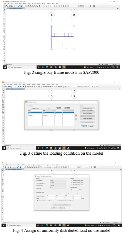
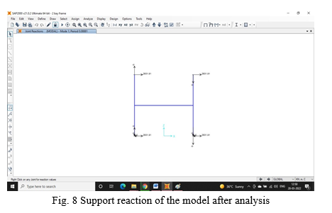
- Prepare a model in SAP2000 to find out the failure of the beam and column of the frame by application of dead load and live load to the frame. In this project two type of frame structure are compared i.e. Single bay frame and 3bay frame.
- The dimension of column and beam are 0.35 m x 0.50 m and 0.40 m x 0.40 m respectively. When the model is prepared then the column and beam design to be checked by the software for the failure condition. In that condition the failure column and beam to be replaced by another dimension but in this frame structure neither beam nor column to be failed in single bay models and 3 bay models. In the following figure the procedure to be followed are shown.
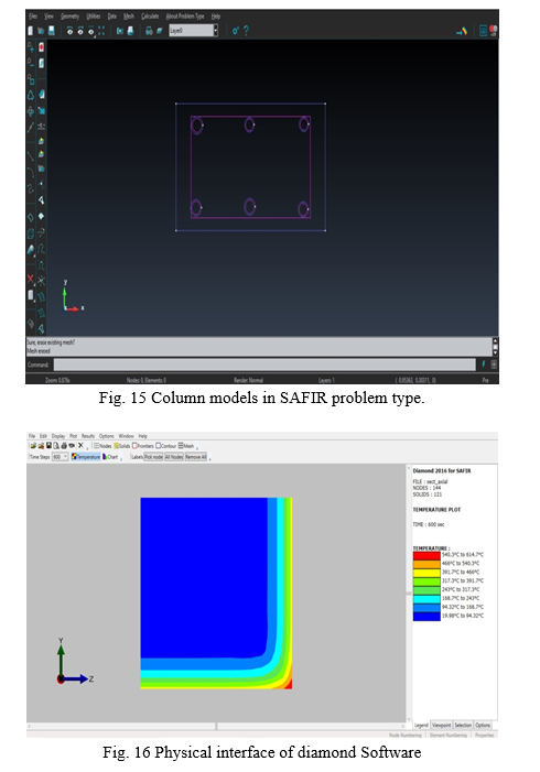
3. After the analysis of the model the column section is designed in the SAFIR software with a base application of GID software. For thermal analysis GID, SAFIR and Diamond software are used which shown the behaviour of the column after the application of fire load.
4. The standard fire curve are presented in IS 3809-1979 code which is taken as reference code for the analysis. The standard fire curve is shown below.
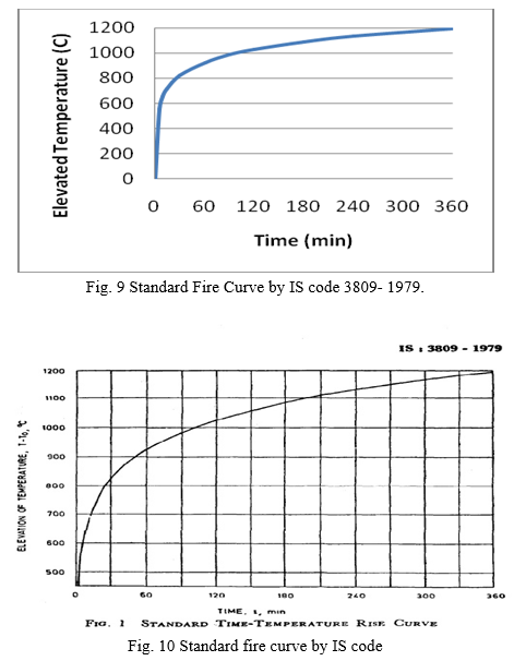
5. The input data is shown in table format for IS code 3809-1979.
Table I
Input data for IS Code 3809-1979
|
Time |
Temperature |
|
0 |
0 |
|
5 |
556 |
|
10 |
659 |
|
15 |
718 |
|
30 |
821 |
|
60 |
925 |
|
90 |
986 |
|
120 |
1029 |
|
180 |
1090 |
|
240 |
1133 |
|
360 |
1193 |
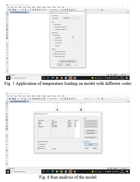
6. The data from various codes are inputted with their various properties. The composite member of steel and concrete are modelled in the SAFIR problem type by using geometry tab then click on create and form rectangle.
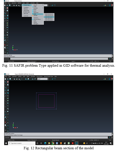
7. Generate the surfaces of the beam by using tab geometry-create-NURBS surface-automatic. Then automatically surface is generated. Then after generation of surface, assigning of material and dimension of the rectangle.
8. Generate meshing to the beam and column of the frame by clicking on Mesh-Generate Mesh. Automatically meshing is generated in the beam and column.
9. Assign the temperature loading with reference of ISO834 curve, ASTM119 curve, F20 curve and user curve. But IS code curve are introduced in this software by clicking on User tab and put down the all data regarding IS Standard fire curve.
10. Calculate the model and save it in the folder. The .xml file to be generated after the analysis.
11. This .xml file of the model is open in Diamond 2016 software whose interface are shown below.
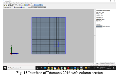
12. Find out all the results regarding column and beam cross-section by using different codes.
???????B. Three Bay Frame Model
Thermal analysis of 3bay frame model to be formed in sap 2000 and their column cross-section is analysed in Safir problem type and then their thermal results are getting from Diamond 2016 software. There are six columns and 3 beams are formed and dead load, live load and temperature load are applied to the frame. There are various codes are used to find out the behaviour of the frame model. In this chapter, the discussion is made about the 3 bay frame model and their result which are calculated in Safir software and diamond software.
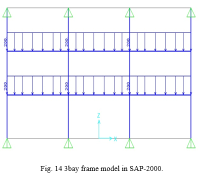
???????C. Procedure for Modelling 3 bay frames
- The three bay frame models are drawn in SAP 2000 software where 6 column and 3 beams are formed. The column sizes are 0.35m x 0.50m and the beam sizes are 0.40m x 0.40m.
- The dead load are assigned to the frame is 2KN/m and the live load are assigned to the frame is 3KN/m. In this the temperature loading also assigned to the frame as per the country temperature in SAP2000 software and then run the analysis of the model.
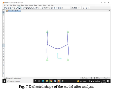
- After analysis the deflected shape of the frame are formed. With this the column of the frame are put in the Safir problem type and assign the material properties to the column cross-section. After that the temperature loading is applied to the column and calculate the result.
In Safir Software the .xml files to be generated. This file is put into the Diamond software for the thermal effect of the column.
IV. RESULT
A. Temperature Evolution Within The Whole Perimeter Exposed Column Cross-Section
The temperature evolution within the whole perimeter exposed to the fire and their results according to the standard fire curve are shown in the table. Here the comparative temperature evolution of the column cross-section due to IS-code, NBCC, NCC and Euro code are shown below and their comparison are also discussed in the graph.
Table II
Temperature evolution within the whole perimeter exposed column cross-section
|
Time |
Temperature |
||||
|
Standard Fire Curve |
IS CODE |
NCC |
EUROCODE |
NBCC |
|
|
0 |
0 |
0 |
0 |
0 |
0 |
|
5 |
556 |
195 |
26 |
26 |
25 |
|
10 |
659 |
287 |
52 |
40 |
26 |
|
15 |
718 |
368 |
70 |
55 |
32 |
|
30 |
821 |
498 |
104 |
82 |
45 |
|
60 |
925 |
673 |
165 |
97 |
58 |
|
90 |
986 |
748 |
210 |
125 |
69 |
|
120 |
1029 |
810 |
277 |
160 |
78 |
|
180 |
1090 |
903 |
365 |
215 |
101 |
|
240 |
1133 |
966 |
445 |
291 |
156 |
|
360 |
1193 |
1073 |
555 |
398 |
198 |
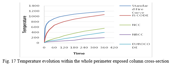
According to the temperature of the country, the behaviour of the column cross-section that exposed to fire is varied. As per the graph, the temperature evolution according to the IS-code is approximately same as that of standard fire curve. In case of NBCC, there is less temperature effect on the column cross-section. In Euro-code the temperature effect is little greater as compare to the NBCC. From this it is clear that, as per the country temperature, the thermal behaviour of the column cross-section is depends.
???????B. Evolution Of Bending Moment In Columns Of The Frame
The bending moment in the column due to thermal effect is formed in the software and the comparative results are found out. The comparative result is shown below.
Table III
Evolution of bending moment in columns of the frame
|
Time |
Bending Moment |
|||
|
IS CODE |
NCC |
NBCC |
EUROCODE |
|
|
0 |
40 |
50 |
-50 |
-50 |
|
500 |
85 |
45 |
-108 |
-95 |
|
1000 |
188 |
28 |
-180 |
-120 |
|
1500 |
250 |
10 |
-230 |
-145 |
|
2000 |
270 |
6 |
-245 |
-165 |
|
3000 |
265 |
5 |
-242 |
-155 |
|
4000 |
250 |
12 |
-235 |
-150 |
|
5000 |
220 |
22 |
-220 |
-140 |
|
6000 |
200 |
33 |
-191 |
-115 |
|
7000 |
180 |
45 |
-175 |
-105 |
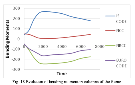
The bending moment produced due to the thermal effect are shown in the above figure. Here IS code has a maximum bending moment produced up to 270 N-m. but in NBCC structure the bending moment has a lower value other than the codes. The higher value produced in NCC code is 50 N-m. In the figure no. 5.5, the comparative bending moment in the column of the frame is shown and the above table shows the values that are taken by the software.
Table IV
Evolution of bending moment in beams of the frame
|
Time |
Bending Moment in beam |
|||
|
IS CODE |
NCC |
NBCC |
EUROCODE |
|
|
0 |
130 |
120 |
-70 |
80 |
|
500 |
165 |
140 |
-48 |
83 |
|
1000 |
235 |
150 |
-25.8 |
75 |
|
1500 |
260 |
153 |
-22.2 |
55 |
|
2000 |
275 |
159 |
-23.8 |
40 |
|
3000 |
270 |
169 |
-24.1 |
35 |
|
4000 |
265 |
175 |
-24.6 |
37 |
|
5000 |
260 |
172 |
-24.9 |
46 |
|
6000 |
250 |
165 |
-25 |
55 |
|
7000 |
238 |
162 |
-25.2 |
62 |
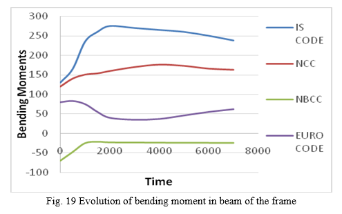
In the beam of the frame, the bending moment is generated according to the various codes. In IS code, it has a greater value i.e. 275 N-m and in NBCC code, it has value of -70 N-m. As the thermal effect increases the bending moment in the beam is also increases. But as per the country effect, the values are shown in the above table and the comparative graph is shown in the figure.
???????C. Evolution of Shear force
A shear force is a force applied along the surface, contrary to an offset force acting the other way. This outcome is a shear strain. In basic terms, one part of the surface is pushed in one heading, while one more part of the surface is pushed the other way.
Table V
Evolution of shear force
|
TIME |
Shear Force |
|||
|
IS CODE |
NCC |
NBCC |
EUROCODE |
|
|
0 |
10 |
-20 |
-25 |
-20 |
|
500 |
35 |
15 |
-75 |
-40 |
|
1000 |
80 |
60 |
-120 |
-50 |
|
1500 |
125 |
115 |
-150 |
-55 |
|
2000 |
155 |
140 |
-155 |
-60 |
|
3000 |
175 |
155 |
-155 |
-61 |
|
4000 |
180 |
150 |
-140 |
-61 |
|
5000 |
176 |
125 |
-125 |
-58 |
|
6000 |
168 |
100 |
-110 |
-55 |
|
7000 |
165 |
85 |
-80 |
-53 |
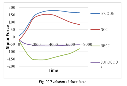
In this the shear force are evaluate from the software for different codes. In this the maximum shear force occur in IS code as compare to the other codes. The graph is plotted in between the time and the shear force. At 4000 second, the shear force for IS code is 180 N and that of Euro code is -61 N.
???????D. Evolution of vertical displacement in beam's mid-span
Vertical displacement refers to the shifting of land in a vertical direction, resulting in uplift and subsidence. In this the vertical displacement occur at the mid span of the beam and the comparative results are shown in the graph.
Evolution of vertical displacement in beam's mid-span.
Table VI
Evolution of vertical displacement in beam mid span
|
Time |
Vertical Displacement |
|||
|
IS CODE |
NCC |
NBCC |
EUROCODE |
|
|
0 |
-0.0031 |
-0.0033 |
-0.0036 |
-0.0034 |
|
500 |
-0.0032 |
-0.0036 |
-0.0045 |
-0.0041 |
|
1000 |
-0.0035 |
-0.0039 |
-0.0046 |
-0.0045 |
|
1500 |
-0.0031 |
-0.0036 |
-0.0048 |
-0.0038 |
|
2000 |
-0.001 |
-0.0012 |
-0.0054 |
-0.003 |
|
3000 |
0.002 |
0.0019 |
-0.0068 |
-0.0025 |
|
4000 |
0.0016 |
0.0015 |
-0.0085 |
-0.0049 |
|
5000 |
-0.001 |
-0.0012 |
-0.0112 |
-0.0072 |
|
6000 |
-0.004 |
-0.0046 |
-0.015 |
-0.011 |
|
7000 |
-0.0065 |
-0.0073 |
-0.02 |
-0.0165 |
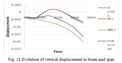
The vertical displacement occurs due to the loading applied on the frame structure. In this the vertical displacement of IS code and NCC has a greater vertical displacement as compare to the NBCC and Euro code.
???????E. Evolution of vertical displacement in column
Column is one of the components of the frame where all the loads are pass from slab to column and then pass to the foundation. Due to the loading occur on the column, it will get buckle. The thermal effect on the column is also the major issue that the column will bend and the vertical displacement occurs.
Table VI
Evolution of vertical displacement in column
|
TIME |
Vertical displacement in column |
|||
|
IS CODE |
NCC |
NBCC |
EUROCODE |
|
|
0 |
-0.0014 |
-0.002 |
-0.0015 |
-0.0015 |
|
500 |
-0.001 |
-9E-04 |
-0.001 |
-0.00096 |
|
1000 |
0.002 |
0.001 |
0 |
0.0009 |
|
1500 |
0.006 |
0.0035 |
0.0014 |
0.0022 |
|
2000 |
0.009 |
0.0066 |
0.0032 |
0.0044 |
|
3000 |
0.014 |
0.011 |
0.006 |
0.0077 |
|
4000 |
0.019 |
0.0135 |
0.0072 |
0.0092 |
|
5000 |
0.023 |
0.015 |
0.008 |
0.0099 |
|
6000 |
0.0247 |
0.0159 |
0.0086 |
0.01 |
|
7000 |
0.0241 |
0.0161 |
0.0082 |
0.0099 |
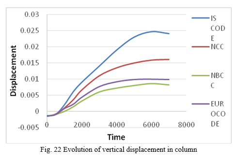
In the above figure shows that the vertical displacement in column due to the thermal loading applied on the 3 bay frame. Here it shows that, the vertical displacement due to IS code gives higher value as compare to the other codes. The vertical displacement at 6000 second for IS code is 0.0247 mm. and that of NBCC, it is 0.0086 mm which is less as compare to other codes.
Conclusion
1) As per the graph, the temperature evolution according to the IS-code is approximately same as that of standard fire curve. In case of NBCC, there is less temperature effect on the column cross-section. 2) IS code has a maximum bending moment produced up to 270 N-m. but in NBCC structure the bending moment has a lower value other than the codes. The higher value produced in NCC code is 50 N-m. 3) In IS code, it has a greater value i.e. 275 N-m and in NBCC code, it has value of -70 N-m. As the thermal effect increases the bending moment in the beam is also increases. 4) In this the shear force are evaluate from the software for different codes. In this the maximum shear force occur in IS code as compare to the other codes. The graph is plotted in between the time and the shear force. At 4000 second, the shear force for IS code is 180 N and that of Euro code is -61 N. 5) The vertical displacement occurs due to the loading applied on the frame structure. In this the vertical displacement of IS code and NCC has a greater vertical displacement as compare to the NBCC and Euro code. 6) The vertical displacement due to IS code gives higher value as compare to the other codes. The vertical displacement at 6000 second for IS code is 0.0247 mm. and that of NBCC, it is 0.0086 mm which is less as compare to other codes. After the whole analysis it is concluded that the suitable design for the thermal analysis is seen in the IS code. The room temperature and the thermal temperature both are different. Thermal temperature impacted on the structure that of room temperature does not adversely affected on the structure.
References
[1] The A.S. Usmani, “Research priorities for maintaining structural fire resistance after seismic damage”, The 14th World Conference on Earthquake Engineering October 12-17, 2008, Beijing, China. [2] Mostafaei, H., “Recent developments on structural fire performance engineering - a state-of-the-art report”, Institute if Research in construction, National research council Canada. [3] B. Santhiya, “Fire Resistant Design of Steel Structure”, International Journal of Engineering Research & Technology (IJERT), ISSN: 2278-0181, Published by, www.ijert.org, SNCIPCE - 2016 Conference Proceedings. [4] Faris A. Ali, “Structural fire engineering”, sustainable built environment. [5] Ian Fletcher, Audun Borg, Neil Hitchen, Stephen Welch, “performance of concrete in fire: a review of the state of the art, with a case study of the winds or tower fire”, University of Edinburgh, School of Engineering and Electronics, Edinburgh. [6] Gabriel Alexander Khoury, “Fire and Concrete”, BE2008 – Encontro Nacional Betão Estrutural 2008, Guimarães – 5, 6, 7 de Novembro de 2008. [7] Anupama Krishna. D, Narayanan S, Priyadarshini R.S, “FE Analysis of Reinforced Concrete Frames Exposed to Fire”, International Journal of Innovative Research in Science, Engineering and Technology, Volume 5, Special Issue 14, December 2016. [8] L.R. Taerwe, “Fire Design of Concrete Structures According to the Eurocodes: A Review”, Designing Concrete Structures for Fire Safety. [9] Guo-Qiang Li, Chao Zhang, and Jian Jiang, “A Review on Fire Safety Engineering: Key Issues for High-Rise Buildings”, International Journal of High-Rise Buildings, December 2018, Vol 7, No 4, 265-285 [10] Ian A. Fletcher, Stephen Welch, José L. Torero, Richard O. Carvel, Asif Usmani, “The behaviour of concrete structures in fire”, Article in Thermal Science · January 2007, DOI: 10.2298/TSCI0702037F. [11] Shoib Bashir Wani, “A Review on Fire Impacts on Concrete Structures”, International Journal of Trend in Scientific Research and Development (IJTSRD) Volume 4 Issue 5, July-August 2020 Available Online: www.ijtsrd.com e-ISSN: 2456 – 6470.
Copyright
Copyright © 2022 Prachi P. Gaurkar, Amey Khedikar. This is an open access article distributed under the Creative Commons Attribution License, which permits unrestricted use, distribution, and reproduction in any medium, provided the original work is properly cited.

Download Paper
Paper Id : IJRASET43781
Publish Date : 2022-06-03
ISSN : 2321-9653
Publisher Name : IJRASET
DOI Link : Click Here
 Submit Paper Online