

Ijraset Journal For Research in Applied Science and Engineering Technology
Comparative Study on Deflection of a Multistoried Building with Shear Wall and Core Wall
Authors: Akeel Firdos Bhat, Er. Vikas Kumar
DOI Link: https://doi.org/10.22214/ijraset.2022.43212
Certificate: View Certificate
Abstract
To ensure the seismic effectiveness of highrise buildings different systems of lateral restraints are provided e.g., bracings, shear walls, core walls etc. In the present study, deflection of various joints, storeys & also the drifts have been gone through. For this purpose, 3 different models of multi-storeyed buildings were prepared consisting of a G+6 building with shear wall at the centre of edges on exterior walls, G+6 building with a core wall & G+8 building with a core wall were prepared using an integrated building designing software known as ETABS- 2016 (student version). A 3-bay building was modelled using M30 concrete mix and reinforcing steel bars of HYSD 415 for beams, columns, slabs as well as shear walls. After this pier labels were assigned to the shear walls. A variety of load cases like joint loads, dead loads, live loads, wind load in x-direction for terrain category 4, earthquake loads in x & y directions for zone II along with their combinations were assigned. The respective diaphragms were assigned to the three models & analysis was carried out at the end. The table of results was obtained and the deflection analysis was carried out to compare the relative effectiveness of shear walls & core walls at different locations of the multi-storeyed building. The codes taken into consideration during the progress of work were IS 456:2000 for plain and reinforced concrete, IS 875:2015 (Part 1) for wind loads & IS 1893:2002 for earthquake loads.
Introduction
I. INTRODUCTION
To counteract the damage caused by the earthquakes a solid concrete or a masonry structure needs to be constructed so that limit states of strength and deflection are not reached. This structure is called a shear wall. In the absence of a shear wall a structure is most likely to collapse or atleast show more deflection. The basic principle behind providing a shear wall structure is to check the development of lateral forces which can cause damage to a structure. Earthquakes in the past have shown the innumerable instances where in absence of a shear wall, a considerable damage to life and property was observed. Foreign countries like USA, England, France etc. have stressed upon the need for construction of a earthquake-resisting structures. In India the necessity for construction of such safe structures was felt only during last decade of the 20th century which saw a great increase in the no. of buildings being built using shear walls, bracings, core walls and like. At the start those structures were built in a random manner but due to advancement in understanding of the pattern of seismic waves and location of epicentres nearly all countries have switched to form some organisations that formed various standards regarding lateral load-resisting construction so that uniform code system is available all over their respective nations.
One of the famous examples where the heights have fascinated all the heads in the world is the sky-touching building of Burj Khalifa. To build it with a total height of 828m and supporting 163 floors all through its height and having a total floor area of 460000 m2 was a next to impossible task for mankind. A large no. of engineers were engaged in the process of its design, assessment, evaluation and performance of the structure. As the methods of construction involving dead loads and live loads were already understandable by man, the problem that was frequently striking the minds of engineers was as to how the tall tower building could be saved from lateral damage. This was the time when the use of shear walls took an effective part in its construction. The two major components of the structure are Floor framing system and Lateral load resisting system.
II. LITERATURE REVIEW
In recent years, the issue of earthquakes has received considerable attention. In tall structures, vertical loads, i.e. dead and live loads, do not pose much of an analysis or design problem as they are largely deterministic. But lateral wind loads or earthquakes are a concern. These loads require special attention in the design of high-rise buildings. These lateral forces can create critical stresses in the structure, cause undesired vibrations, or cause excessive directional movement of the structure. emphasizes the importance of limiting sway when subjected to lateral loads. Extensive research efforts have been devoted to the seismic behaviour of different types of frames and shear walls. In this chapter, some of the existing literature on the above issue has been discussed.
- Fayazuddin Ahmed Syed, B. Dean Kumar, Y. Chandrasekhar, B.L.P. Swami(2012): This study was conducted to know about the behaviour of Flat plate multistoried frames with and without shear walls when they are subjected to wind loads. In this study 20, 40, 60 & 80 storied building frames were made and they were analysed under STAAD Pro V8i after assigning wind loads to it. They concluded that shear walls with flat plates help in reducing the axial load on columns even in the middle frame region contribute towards substantial reduction of drift in a high building.
- Pradyut Anand (2021): This study titled “A Review on Performance of Shear Walls and Cost Optimization of the Structures based on Different Shear Walls Position” was aimed at compring the deflection in G+10, G+15 buildings with bare frames with those of G+10, G+15 buildings with shear walls. The conclusions drawn out of this paper were that shear walls lead to minimisation of lateral movement in the modelled building as well as in the actual ground structure increasing safety factor & for cost optimisation shear walls should be located at the middle of exterior of building.
- Ghobarah, M. Youssef (1999): This study was performed with models representing the bending behaviour of walls at different degrees of accuracy.The model consisted of non-linear springs connected by linear beam elements. The model response predictions are tested to be in close agreement with the experimental measurements. This study came out with the point that RC bearing walls are an important element to resist lateral loads.
- Donthireddy Raja, Shekhar Reddy , Joshi Sreenivasa Prasad: titled “Seismic analysis of multistoreyed building with shear walls of different shapes” which concluded that shear walls increase the stiffness of a building and prevent its excess deformation under seismic loads.
- Prathamesh P. Mohite , Shubham B. Sonawane , Chinmay R. Thatte , Omkar B. Udeg, Dr. Amardeep D. Bhosale: titled “Stability of high rise building using shear wall by ETABS” which arrived at the conclusion that addition of shear wall increases the stiffness of the building resulting in reducing the time period of the building with shear wall by 18% as compared to the building without shear wall & due to increasing in stiffness in response the base shear for the building with shear wall is increased by 21% than due to the building without shear wall. They also observed that due to increase in stiffness response to base shear for the building with a shear wall is increased by 21% & shear wall in building reduces maximum displacement, base shear and story drift as compared to building without shear.
- Reeba Mary Cherian, Aswathy S Kumar under the name “Seismic analysis of multistoried symmetrical building based on shear wall positions” in which an attempt was made to study the dynamic behaviour of building with shear walls provided at 4 different positions, i.e., at core (full height of the building), core (soft storey), sides (full height of the building) and sides (soft storey). The parameters obtained from the analysis include storey drift, storey shear and storey displacement. The best position of shear wall was obtained from the analysis. The best results obtained during analysis overcomes the destruction occuring during an earthquake. A comparative table of these results for the analysis was also presented. This study came out with the conclusion that maximum storey shear and maximum storey displacement is lowest when the shear wall is placed in the core position (soft storey) and greater when the shear wall is placed at the sides (soft storey as well as full height of the building) and also the core (full height of the building). Secondly, maximum storey drift is lowest when the shear wall is placed at the sides (full height of the building) when compared to shear walls placed at the core (full height of the building, soft storey) and sides(soft storey).
- Varian U.H et al (2002) described about shear walled buildings under horizontal loads. Considering in his design “Reinforced concrete framed buildings are adequate for resisting both the vertical and the horizontal loads acting on shear walls of a building”. In his 2nd edition 2002 of “Design of structures”. He gave rigidity of shear wall, tensional rigidity and shear centre of a building in detailed description.
- Duggal S.K with his profound interest on structures gave a detailed description about reinforced concrete buildings in his book “Earthquake-resistant design of structures” describing a wall in a building which resist lateral loads originating from wind or earthquakes are known as shear walls”. He considered flexural strength in the wall to be dominant force based on which design of structure to be carried out in tall shear walls. He described in detail about various types of shear walls with their load bearing capacities as per code requirements.
- Prathibha Reddy T, Vinutha S, Khaled Mahdi AL-Qudaih (2021): This work was on the analysis of symmetrical and multistoreyed R.C.C building, that was G+15 storey bare frame with fixed support under wind and seismic conditions i.e., with shear walls, without shear walls and with bracing. It revealed that with shear walls the deflection produced was only 7.72% as compared to 50.11% when no shear walls were provided.Also for high seismic performance shear walls should be located symmetrically in a building.
- Mr.Hardik Mandwe, Simran Kagale, Pooja Jagta, Kalyani Patil (2021): This study was aimed at examining the effect of shear walls in a multistoried building using STAAD pro. The study was done on a commercial building and it ended up with the following conclusions:
a. STAAD Pro is a versatile software which can be employed to calculate the reinforcement used in design of a concrete shear wall for reducing its sudden failure without warning.
b. Max. displacement due to seismic waves is less with shear walls RC framed buildings.
11. Vishal V. Gupta, Ashwin Soosan Pillai, Akash Bharmal, Jaydeep. B. Chougale (2020): This study under the title “Study of Effect of Orientation of Column and Position of Shear Wall on G+13 Storeyed Earthquake Resistant Structure” was carried on a 14 storey building model and having a storey height of 3.5m. The plan provided was regular in shape. In relation to the presence of shear wall in a building it produced the following conclusions:
a. The location of shear wall and brace member has a significant effect on the seismic response.
b. Shear wall construction provides large stiffness to the building.
c. Economic design is ensured when the shear walls are provided as mirror images of each other
.12. Jawid Ahmad Tajzadah, Prof. A. N. Desai, Prof. Vimlesh V. Agrawal: This study lead to the conclusion that shear wall placed at building core has appreciable seismic response as compared to other options due to more tendency of attraction of lateral loads. As shear wall are set apart from centre of the building, its seismic response gets reduced. It also concluded that for improving torsional resistance in buildings provided with shear wall, they are placed as much as possible apart from centre of mass of the building.
13. Rajiv Banerjee, J. B. Srivastava: This research concluded that shear walls are highly important in high-rise buildings for resisting lateral forces. But it is important to note that the location of shear walls plays a crucial role in determining the efficiency of shear wall. If the location of shear wall is such that it results in an increase in torsional forces, it becomes a dangerous enemy of the structure. Thus, one has to put the shear walls such that centre of mass and centre of stiffness of the building should be as close as possible. It is also possible that, some configuration of shear walls may cause a considerable reduction in lateral displacements but large eccentricity, which in turn cause torsional forces in the structure. Thus, a balance has to be set up in the configuration of shear so that both the lateral forces along with torsional forces are eliminated to a greater extent.
III. METHODS OF ANALYSIS
Determination of earthquake loads on a structure is the challenging job in the field of structural engineering. A lot of research work is carried out in this regard to propose the simplified methods that can predict the results with a high amount of reasonable accuracy. It was found that except detailed non-linear time history analysis, the available methods have limited areas of the application and cannot be used for all type of buildings. Structural response to earthquakes or seismic response in buildings is a dynamic phenomenon & it depends upon the dynamic characteristics of structures and also on the intensity, duration and frequency of the exciting ground movement. Although the seismic action is dynamic in its nature, building codes often recommend equivalent static load analysis for design of earthquake-resistant buildings due to its simplicity & result-yielding nature. This is done by focussing on the predominant first mode response and formulating equivalent static forces that produce the corresponding mode shape with various empirical adjustments for higher mode effects. The reason behind the use of static load analysis to establish seismic design quantities is justified in view of the complexities and difficulties associated with dynamic analysis. Dynamic analysis proves to be even more complex and questionable when we consider non-linearity in materials and geometry. Hence, the analytical tools used in earthquake engineering have been a subject for further development and with significant advances and enhancements achieved in recent years.Despite the above mentioned concerns over the dynamic analysis to be used in seismic design, it is practically useful to carry out special studies of tall and irregular structures because of its superiority in reflecting seismic response more accurately provided it should be used properly. These studies cover a large number of analysis under different ground motion and different structural parameters to provide more clear view of the structural behaviour. With the advancement of personal computers and the consequently the reformation in information technology coupled with extensive research work in the field of non-linear modelling, more reliable computational tools have been made available for use in design of buildings.
Popular methods of seismic analysis used in estimating the earthquake demand on the structure under consideration can be discussed as below:
A. Linear Static Method
This method, also known as Equivalent Static Method, is used to estimate the earthquake demand for the structures whose response is particularly governed by the first mode and expected to be in elastic range. In this method the lateral loads are estimated & calculated based on the fundamental period of the structure and they are applied on the design centre of mass at each floor level and then the demands are estimated. The magnitude of these pseudo-lateral loads has been selected with the intent that when such loads are applied to the linearly elastic model of the building, it will cause design displacement which is expected during the design earthquake.If the structure responds elastically to the design earthquake, the calculated internal forces will be a reasonable approximation of the ones expected during the design earthquake. If the building responds elastically to the design earthquake which is usual in most of the cases, the actual internal forces developed in the building will be less as compared to the internal forces calculated using the pseudo-lateral loads.
IS 1893:2002 uses the account the Response Reduction Factor (R) is used to calculate the reduced forces empirical formulae to estimate the fundamental time period of the structure. It is used for determination of spectral acceleration from the response spectrum, which in turn is used for the calculation of Base shear modified by the use of some coefficient. After this the base shear is distributed in the parabolic manner along the height of the building. In addition to this, the effect of the torsion is taken into consideration by calculating the design center of mass by considering design eccentricity. Design eccentricity is defined as the sum of actual eccentricity (distance between centre of mass and centre of rigidity at floor level) and accidental eccentricity (5% of the horizontal dimension at the floor level mentioned but measured perpendicular to the direction of the applied load). For 2-D modelling the design forces are suitably increased to take into account the effect of torsion. This method is used by IS 1893:2002 with the steps below:
- Calculate the Design Load
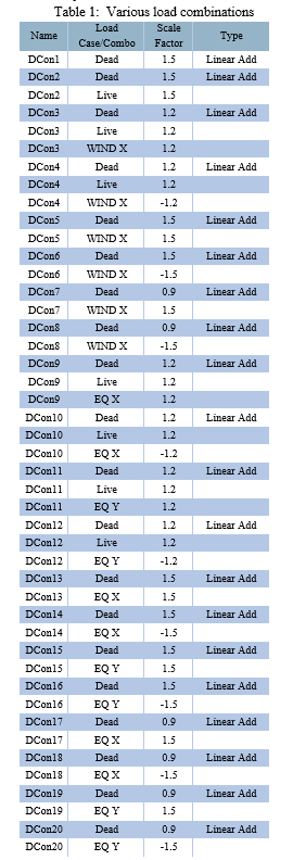
The load factors for the design of the reinforced concrete structures as provided by the code are:
1.5 (DL + LL)
1.5 (DL ± EL)
0.9 DL ± 1.5 EL
1.7 (DL + IL ± EL)
2. Determine the design Horizontal Seismic Coefficient (Ah)
The design horizontal seismic coefficient Ah is determined by the following expression:
Ah=Z I Sa /2 g R
Where, Z = Zone factor
I = Importance factor
R = Response reduction factor
Sa/g = Spectral acceleration coefficient
3. Determine Fundamental Natural Period of vibration (T)
The approximate fundamental natural period of vibration (in s) in case of all other buildings including moment-resisting frame building with infill panels, may be determined by the expression:
T= 0.09h / d1/2
The approximate fundamental natural period of vibration (in s) in case of moment- resisting frame building without brick infill panels may be determined by the following empirical expression:
T= 0.075h0.75 ( RC frame building ) & T=0.085h0.75 ( steel frame building)
4. Calculate Seismic Weight
The seismic weight of each floor is taken as its entire dead load and appropriate amount of imposed load. The seismic weight of each floor is found out by distributing equally the weights of walls and columns in a storey to the floors below & above that storey. Total seismic weight of the building is the summation of seismic weights of all the floors.
5. Assign the IMPORTANCE Factor
The structures are assigned an importance factor which depends upon the functional use of the structure & characterized by the hazardous consequences of its failure, post-earthquake need etc.
6. Response Reduction Factor
Depending upon the estimated seismic damage performance of a structure mainly based on the ductile or brittle deformations response reduction factor is assigned.
7. Design Seismic Base Shear
The total design lateral forces or design base shear (Vb) in any principal direction shall be determined by the following formula:
Vb=AhW
Where, W= total weight of the building calculated using the structural details,
Ah = Horizontal Seismic Coefficient
8. Compute distribution of Design Force
The design base shear (Vb) computed by the above equation shall now be distributed along the height to different floors under consideration as per the expression:
Qi=VbWihi2/∑j=1 to nWjhj2
Where, Qi = Design lateral force at ith floor,
Wi = Seismic weight of ith floor,
hi = Height of ith floor measured w.r.t base
n = Number of storeys
The equivalent static force procedure is permitted for building in low seismic regions, regular building below some height limit, and short building having certain irregularities. It may be a good choice by designers owing to its simplicity when dynamic analysis is not required.
B. Linear Dynamic Method
Dynamic analysis is conducted in order to obtain a linear (elastic) or a non-linear (inelastic) structural response of a structure. When elastic analysis is gone through, an empirical assessment of inelastic response is made as the design philosophy is based on non-linear behaviour of buildings under strong earthquakes. Inspite of all this engineering do not deter from preferring linear dynamic analysis owing to its simplicity and direct correspondence to the design response spectra given in building codes.This involves two methods:
- Response Spectrum Method: Here the load vectors are calculated corresponding to pre-defined number of modes. These load vectors are then applied at the location of design centre of mass to calculate respective modal responses. The modal responses are then combined as per SRSS or CQC rule to obtain the total response. From the basics of dynamics it is now quite clear that modal response of the structure subjected to a particular ground motion is estimated using the combination of results of static analysis of the structures subjected to corresponding modal load vector and dynamic analysis of the corresponding single degree of freedom system subjected to same ground motion. After this, the static response of MDOF system is multiplied by the spectral ordinate obtained using dynamic analysis of SDOF system to get that modal response. Same procedure is used for other modes and the results are arrived at by making use of SRSS or CQC rule. In response spectrum method of analysis the spectral values are read from design spectrum which are directly multiplied by the modal load vector and the static analysis is conducted to determine the corresponding modal peak responses. This method is known as CLASSICAL MODAL ANALYSIS.
- Time History Analysis or Response History Analysis: Dynamic analysis by time history analysis method is used to calculate the building responses at discrete time steps by making use of discrete record of synthetic time history as base motion. If three or more time history analysis are done, only the maximum responses of the parameter of interest are chosen. There are two methods by which the time history analysis is carried out either by Non-linear modal time history analysis or by Non-linear direct integration time history analysis.
C. Non-linear Static Method
This is the procedure in which the structure is pushed till collapse to generate the pushover curve, which is then used to obtain the target displacement at which the response quantity is extracted from the deformed model. Non-linear static analysis or Pushover analysis method has been developed over the past years and it has become the preferred analysis method for design as well as for carrying the seismic performance evaluation because of it being relatively simple and also because it considers post-elastic behaviour. However, the procedure involves certain approximations, assumptions & simplifications that some amount of variation is bound to exist while estimating seismic demand prediction of pushover analysis. Pushover analysis is a static, non-linear procedure which uses simplified non-linear technique for estimation of seismic structural deformations. It is an incremental type of static analysis used to form the force-displacement relation, or the capacity curve, for a structure or a special structural element. The analysis involves applying horizontal loads, in a prescribed way, to the structure incrementally (pushing the structure and plotting the total applied shear force and corresponding lateral displacement at each increment) all the way upto the collapse condition. In non-linear static analysis, demand is represented by making an estimation of the displacements or deformations that the structure is expected to show. The physical model used in the static non-linear pushover analysis is based on the procedure put forward by the ATC-40 and FEMA 273/274 document which defines the force-deformation criteria for the hinges used in the analysis. The Structural Performance Level of a building shall be chosen from 4 discrete Structural Performance Levels and 2 intermediate Structural Performance Ranges & the design procedures cum acceptance criteria corresponding to these Structural Performance Levels shall be as specified in FEMA 356.
D. Non-linear Dynamic Analysis
This is the most accurate and acceptable method used to determine the seismic response of structures. In this method the structure is subjected to actual ground motion which is the representation of the ground acceleration vs time curve. The ground acceleration is determined at small time step so as to give the ground motion record. Then the structural response is calculated at every instant of time to gather information regarding its time history and the peak value from this time history is selected as design demand. Hence a Mathematical model incorporating the nonlinear characteristic of individual component and element of the building directly shall be subjected to seismic shaking & represented by ground motion time history to obtain forces and the displacement (FEMA 356). Since numerical model directly takes into account the effect of material non-linearity, inelastic responses and calculated internal forces will be a reasonable approximation for those expected to be observed during the design earthquake.
IV. METHODOLOGY
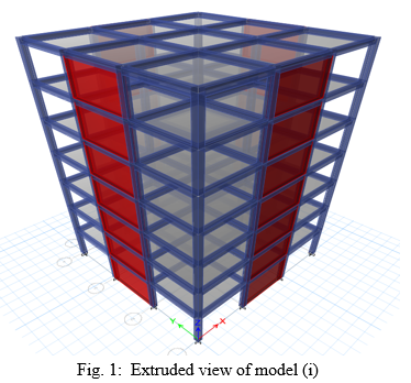
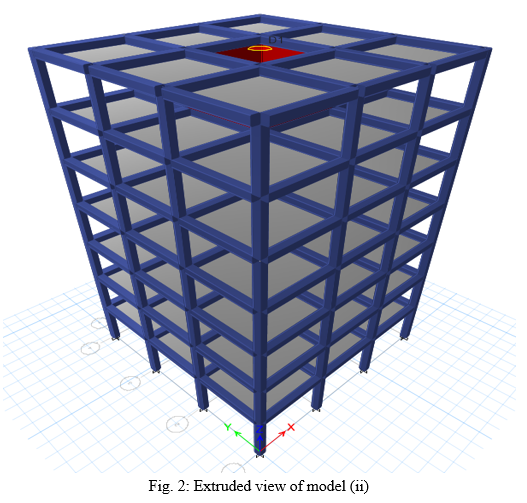
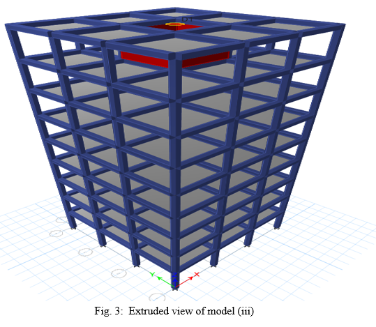
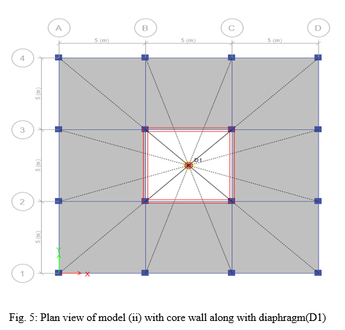
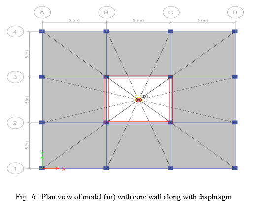
The methodology starts with modelling the structure prototype in ETABS. 3 different models are prepared for the same purpose which include the following:
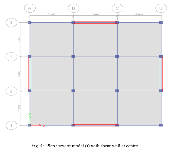
- G+6 multi-storeyed building with a shear wall at centre on exterior faces.
- G+6 multi-storeyed building with a core wall at exact centre.
- G+8 multi-storeyed building with a core wall at exact centre.
Apart from studying the effect of location of shear wall on the deflection and storey drift of a building keeping the height same, the effect of height of a building on the deflection and storey drift keeping the shear wall on the core is also studied. Pushover method of analysis is used in current study to analyse the models made.
A. Model geometry
Number of Storeys:
Model (i)=7
Model (ii)=7
Model (iii)=9
Storey Height:
Model (i)=Bottom storey- 4m + other storeys-3.5m
Model (ii)= Bottom storey- 4m + other storeys-3.5m
Model (iii)= Bottom storey- 4m + other storeys-3.5m
Number of Bays along X-direction= 3
Number of bays along Y-direction =3
Bay Width along X-direction =5m
Bay Width along Y-direction =5m
Size of Column=400mm *400mm
Size of Beam=Depth-450mm +width-375mm
Thickness of Slab=300mm
Thickness of Shear Wall = 250mm
B. Information Regarding the Actual Structure
Frame Type – Ordinary moment resisting frame
Seismic Zone (Z) – II
Response Reduction Factor (R) – 5
Importance Factor (I) –1
Response Spectrum– As per IS 1893 (Part- I) 2002
Wind Speed – 45 m/s
Terrain Category – 4
Class of Structure – Exposed from bottom to top
C. Loading
Joint load= 1 kN
Dead Load:
Beam=4.2 kN/m
Column=4 kN/m
Slab=7.5 kN/m2
Shear wall=6.25 kN/m2
Live Load=3 kN/m2
Earthquake Load in x direction (EQ X)=1.5 kN/m2
Earthquake Load in y direction (EQ Y)= 1.5 kN/m2
Wind Load in x direction (WIND X)= 0.8W
D. Material Properties
Grade of Concrete – M30
Grade of Steel – HYSD 415
Modulus of Elasticity of concrete –200000MPa
Poisson’s Ratio –0.2
E. Steps for Analysis
- After the modelling of the structure is completed, Pier Labels are assigned to the walls drawn to make them recognise and function as shear walls.
- Various types of loads like Joint loads, Dead loads on various elements, Live loads and other lateral loads are assigned to the structure using the command “ Assign” from the ETABS.
- The load cases which are already assigned to the structural model are now required to be combined so as to form various load combinations as per standards of IS 456:2000. It is done by using the command “Load Combinations” in ETABS.
- Next assign the Diaphragm in the software using the command “Shell assignment” under the tab “ ASSIGN” to the structure so that analysis can be done at the last.
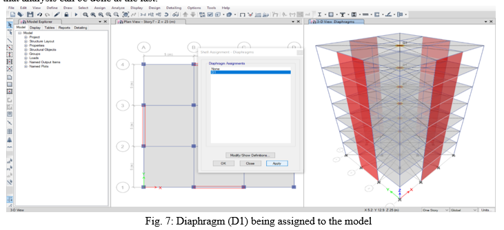
A diaphragm is point through which the lateral loads imposed on a building are transferred down to the vertical members all the way to the foundation of the structure.
5. Now using the command “Analyse” and select the option “ CHECK MODEL” to look for any warning and finally analyse the model in ETABS using the command “Run Analysis”.
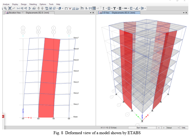
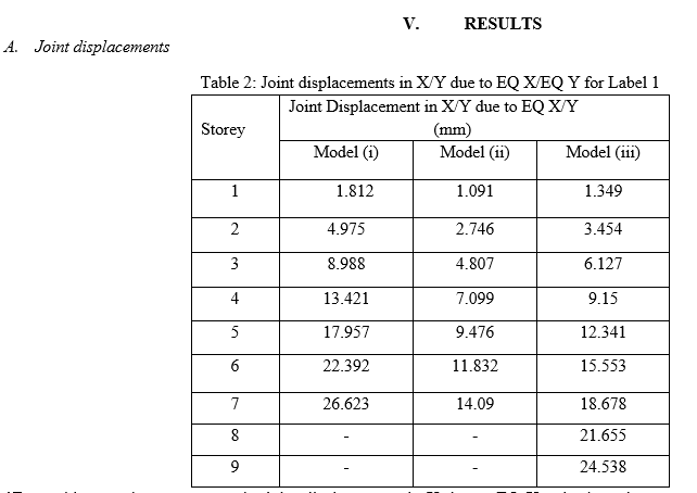
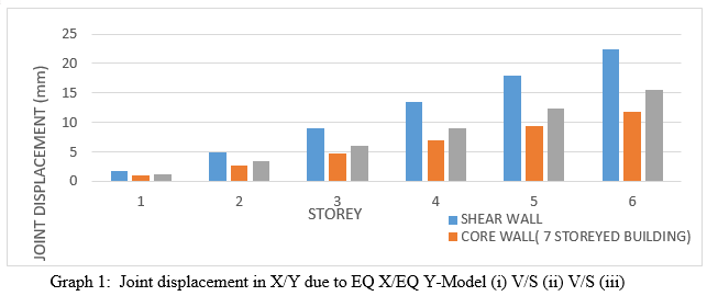
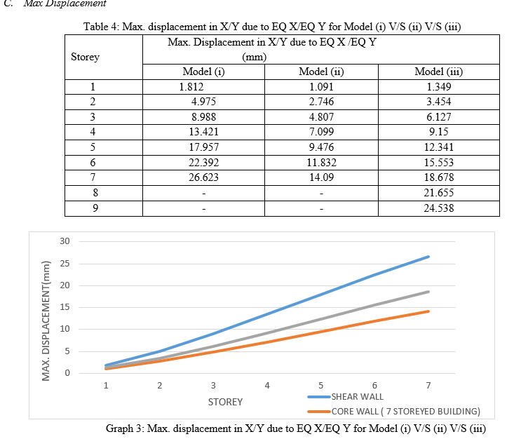
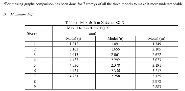
*For making graphs to compare the joint displacements in X due to EQ X only the values upto Storey-7 have been taken into consideration thus, ignoring Storeys-8 & 9.
Conclusion
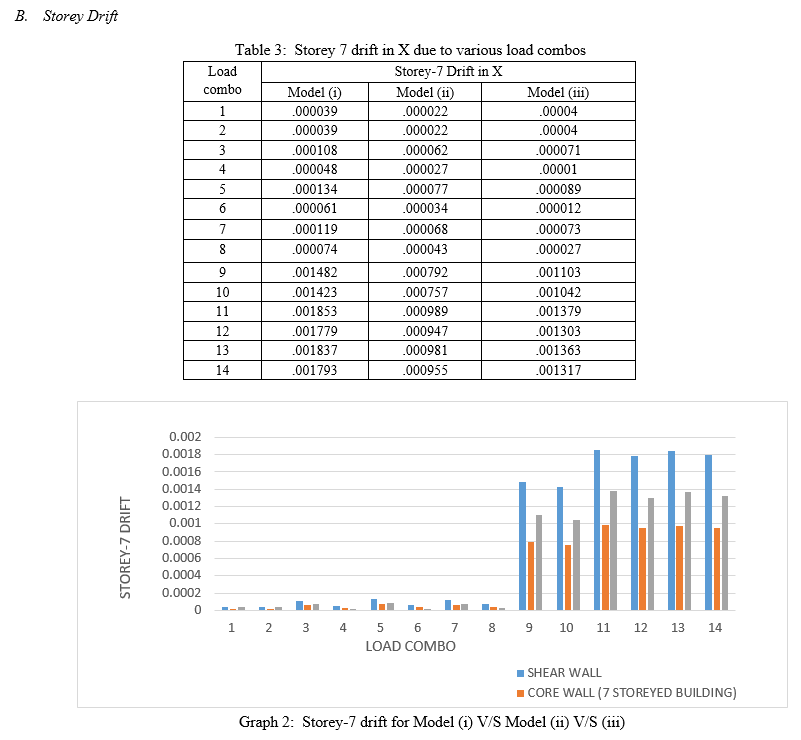
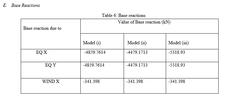
1) Majority of the lateral forces are taken by Shear walls. 2) For majority of the cases, when shear wall is provided at the core storey drift and joint displacement is lesser as compared to when the same wall is provided at the centre of exterior walls. 3) Keeping the storey height constant, Maximum displacement and Maximum drift of a building is more when the shear wall is provided at the central core of the building. 4) Keeping the position of shear wall fixed at the core of the building, Max. displacement and Max. drift of that building is lesser when the height of the building is lower. 5) If the height of the building is increased further, it becomes unsafe due to increase in the lateral forces and decrease in the magnitude of lateral restraints. 6) For economy shear walls should be put symmetrically around the building. 7) Value of base reaction is more for a building with a core wall and greater height. 8) Torsional damages and fundamental time period is minimized due to provision of a shear wall.
References
[1] G. Jaeger, A. A. Mufti, J. C. Mamet, “The Structural Analysis of Tall Buildings having Irregularly Positioned Shear Walls.” Build. Sci. Vol. 8. 1973, Page no. 11-22. [2] S.K. Duggal, “Earthquake resistant design of structures” Page no. 301, 8.12 about Shear Walls. [3] Jaimin Dodiya, Mayank Devani, Akash Dobariya, Mehul Bhuva, Kamalsingh Padhiar, ““Analysis of multistoreyed building with shear wall using ETABS ”, Vol. 5 Issue 2 ,2018 published in IRJET. [4] Priya Kewat, Kavita Golghate (2020), “Effect of shear walls at different locations with varying thickness in multi-storeyed buildings” ,Vol. 7, Issue 12, IRJET, ISSN (online): 2395-0056. [5] Sanisha Santosh, Linda Ann Mathew(2017), “ Seismic analysis of multistoried building with shear walls of different shapes”, Vol. 6, Issue 6, IJERT, ISSN: 2278-0181. [6] Dr. Laju Kottallil et al (2014) “Effect of shear wall location in buildings subjected to seismic loads”, IOSI Journal of engineering and computer science, Volume 1 Issue 1. [7] P. P. Chandurkar, Dr. P. S. Pajgade (2013), “Seismic Analysis of RCC Building with and Without Shear Wall”, International Journal of Modern Engineering Research (IJMER), Vol. 3, Issue. 3, p-1805-1810. [8] Prathamesh P. Mohite , Shubham B. Sonawane , Chinmay R. Thatte , Omkar B. Udeg , Dr. Amardeep D. Bhosale (2022), “Stability of High Rise Building using Shear Wall By ETABS”, International Journal of Engineering Research and Technology, Vol. 11, Issue 4, ISSN: 2278-0181. [9] Bongilwar, R., Harne, V.R, Chopade ., Significance of Shear Wall in Multi-Storey Structure With Seismic Analysis. IOP Conf. Series: Materials Science and Engineering 2018. [10] IS: 456 - 2000 “Code of Practice for Plain and Reinforced Concrete”, Bureau of Indian Standards, New Delhi, India. [11] IS: 1893 (Part I) - 2002 “Criteria for Earthquake Resistant Design of Structures”, Bureau of Indian Standards, New Delhi, India.
Copyright
Copyright © 2022 Akeel Firdos Bhat, Er. Vikas Kumar. This is an open access article distributed under the Creative Commons Attribution License, which permits unrestricted use, distribution, and reproduction in any medium, provided the original work is properly cited.

Download Paper
Paper Id : IJRASET43212
Publish Date : 2022-05-24
ISSN : 2321-9653
Publisher Name : IJRASET
DOI Link : Click Here
 Submit Paper Online