

Ijraset Journal For Research in Applied Science and Engineering Technology
Design and Development of IoT based Industrial Gas Leakage Monitoring System
Authors: Mourya Sirapu
DOI Link: https://doi.org/10.22214/ijraset.2022.40358
Certificate: View Certificate
Abstract
Gas leakages are a hazardous threat to living beings present in the vicinity and cause serious health issues when exposed. Employees need to constantly monitor the situation and if any leak occurs he/she needs to make the right decisions which sometimes may be prone to error. A system needs to be created that bypasses human intervention and constantly monitors around the clock. The input to the system is given by a sensor whose sensitivity depends on the gas it needs to detect. The concentration of the gas is directly proportional to the voltage output. On receiving the information, a microcontroller operates an alarm, monitoring system and displays the output with the help of LCD, LEDs. An Internet of Things (IoT) infrastructure is created in such a way that people, who are connected to the same Wi-Fi, will get a message and authorities present outside the organization will get an email via a cloud-based applet wherein officials can monitor using data analytics platform from a safe location via the internet. Officials will be able to monitor all the areas placed with a sensor on a single dashboard. From the dashboard, the data is received by a microcontroller which then initiates the sprinkler system. The microcontroller, present at the leak, operates a solenoid valve thereby directing the sterilizing agent at the site of the leak.
Introduction
I. INTRODUCTION
Gas leaks can be attributed to a man-made disaster. Improper design, damage to the material, improper installation and maintenance, lack of handling expertise are some of the ways that lead to gas leaks. Common types of industrial gases include carbon dioxide, carbon monoxide, mono oxides of nitrogen. Dust, smoke released from industries causes air pollution. They hinder muscular functioning. Gases like CO2, SO2, and NO2 combine with rainwater creating respective acids. The productivity of the soil is impeded due to acidification. The acidity of water bodies increases which cause the decline in the population of aquatic organism. Acid rain also leads to corrosion of historical monuments. Industrial gases create photochemical smog which causes eye itching and respiratory problems. The smog reduces the transparency of the atmosphere and creates a problem for pilots and planes. A potential leak of any lethal gas may pose a significant threat to living things and the environment. It will have a lasting effect spanning decades and inhibiting serious health issues. Some gases lead to genetic abnormalities. Gas leaks into the atmosphere cause global warming and ozone depletion. Some gases rapidly diffuse with air thereby decreasing countermeasure time. The risks of explosion, fire, suffocation are based on the properties of the gas.
Underground gas leaks lead to land degradation, pollution of underground water making the land uninhabitable for decades to go. The number of gas-related accidents is on the rise. This situation requires immediate attention so that future devastating accidents can be mitigated. This paper talks about gas detection system which does not include human participation. The system monitors around the clock. Whenever the concentration of particular gas increases, the system takes the necessary steps to inform concerned authorities. The alarm, lights, display come into action. With the help of local networks and IoT-based platforms, the employees working in the organization will get messages, notifications, and emails. The sensors can be installed in critical areas and can be monitored simultaneously on a common dashboard at any location with stable internet. The system can be further improvised by pulling data from the dashboard and sending it to the microcontroller which then initiates the sprinkler system. Relays, which can be used to operate solenoid valves, are present on every microcontroller present in the vicinity of the leak. The solenoid valve directs the neutralizer agents towards the point of the leak. Additional upgrades can be implemented by creating automatic exhaust systems; lockdown protocols can be initiated in the form of gate systems. The system requires little wiring, is portable, and is maintenance-friendly. It is easy to install and takes up a very small space. The system can be customized to detect any type of gas. It is cost-effective, reliable, and can be quickly produced.
II. LITERATURE SURVEY
I have explored various articles, posts, documentaries regarding gas leaks in the past. There are myriad reasons that led to the leaks. The damage it caused is unfathomable whether it may be in terms of money, lives, or the environment. Controlling the system needs patience while monitoring and decision-making capabilities under difficult situations. Some of the most prominent problems found in current industries are as follows.
- The system is very expensive and was found in large-scale industries. The system is not maintained periodically.
- The systems are primitive using relays and timers. Employees are needed for constant monitoring and for controlling purposes.
- Humans are instructed to initiate lockdown protocols and alert authorities when a leak occurs increasing the time to take appropriate measures.
- Everything is wired which makes the maintenance difficult and to alert people the same old siren is used.
- The latest countermeasures such as the deployment of sterilizing chemical agents or venting out the harmful gases into the separate chamber, initiation of sprinkler system are not present.
- Factories have no regard for the environment because in the name of expansion the proprietors are clearing the forest area around. The common public knowingly or unknowingly is relocating to places near factories.
The most prominent factor is time; if authorities had enough time to assess the situation and take appropriate action then a lot of lives could be saved thereby limiting the destruction.
III. WORKING
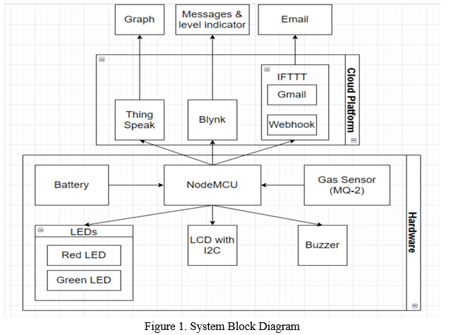
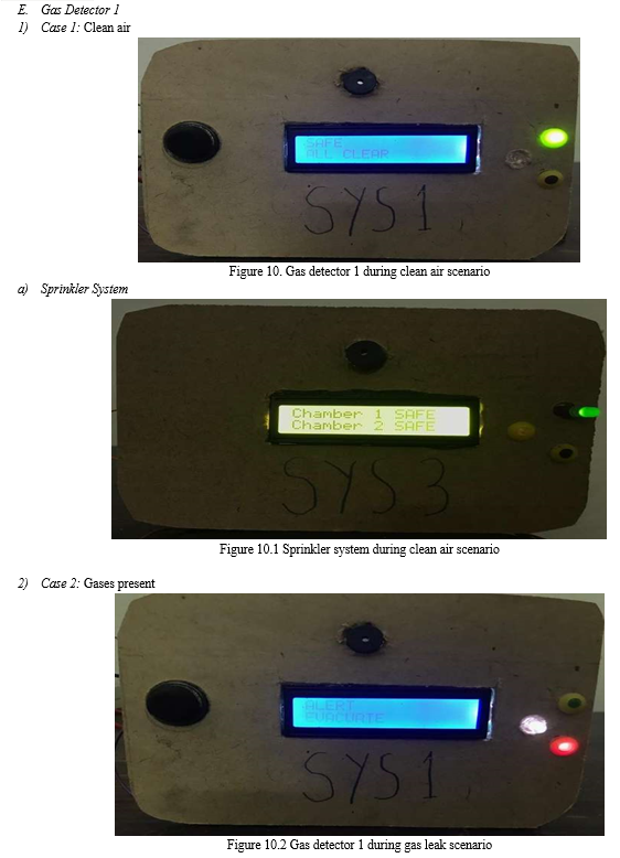
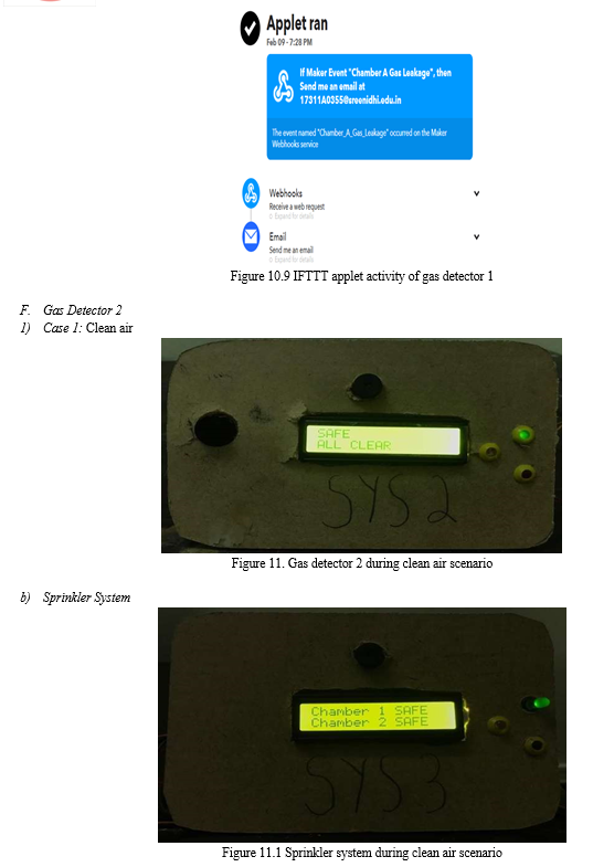
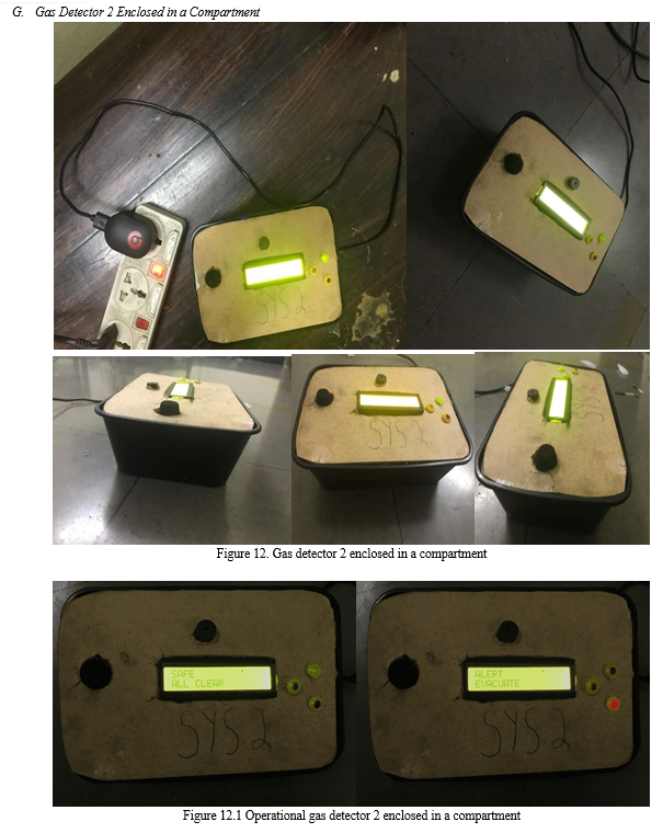
The project uses NodeMCU with a built-in ESP8266 Wi-Fi module. To detect gases MQ-2 semiconductor sensor is installed. The sensor constantly feeds the analog data into NodeMCU when a threshold is reached an appropriate output will be given. The sensor takes input whereas LEDs, LCD with i2c, buzzer gives output. There are two LEDs present which are named green and red. The green LED, as shown in figure 10, is switched on when there are no gases present notifying that the atmosphere is safe. The red LED, as shown in figure 10.2, is switched on when there are gases present notifying the atmosphere is not safe. The buzzer is switched on when gases are present notifying that the atmosphere is not safe. The LCD with i2c flashes messages, as shown in figure 10, such as “SAFE” and “ALL CLEAR” when no gases are present in the atmosphere but when gases are present the messages, as shown in figure 10.2, changes to “ALERT” and “EVACUATE”.
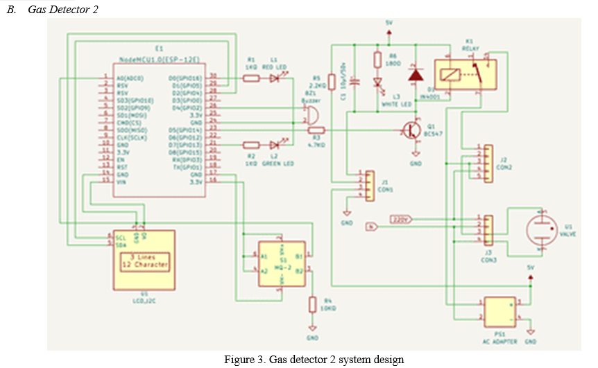
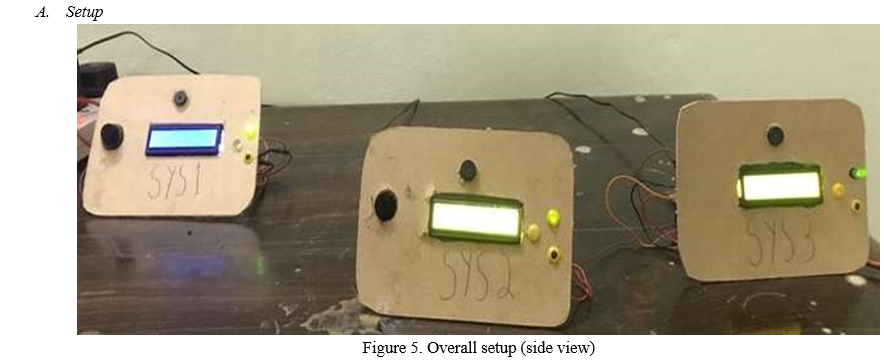
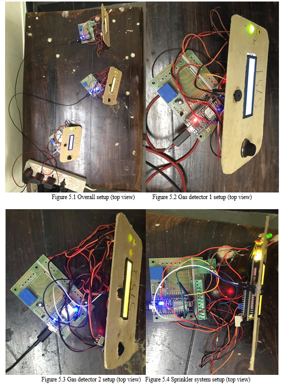
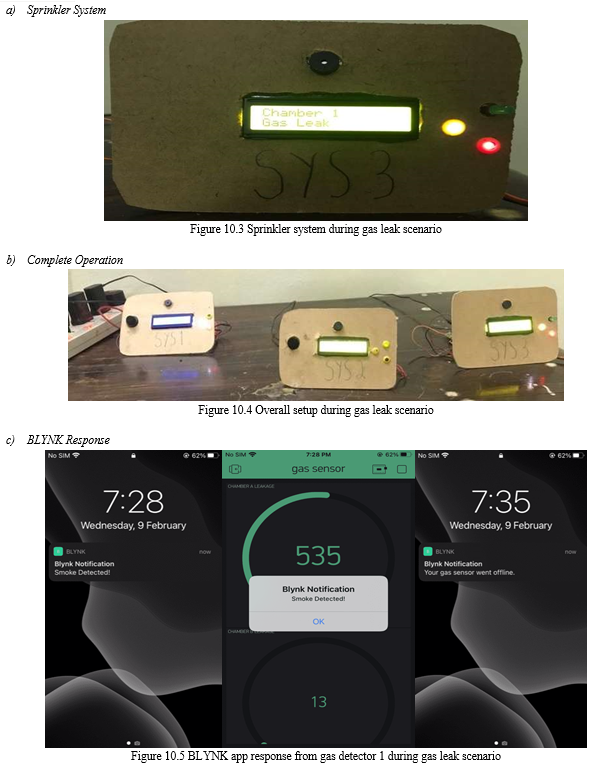
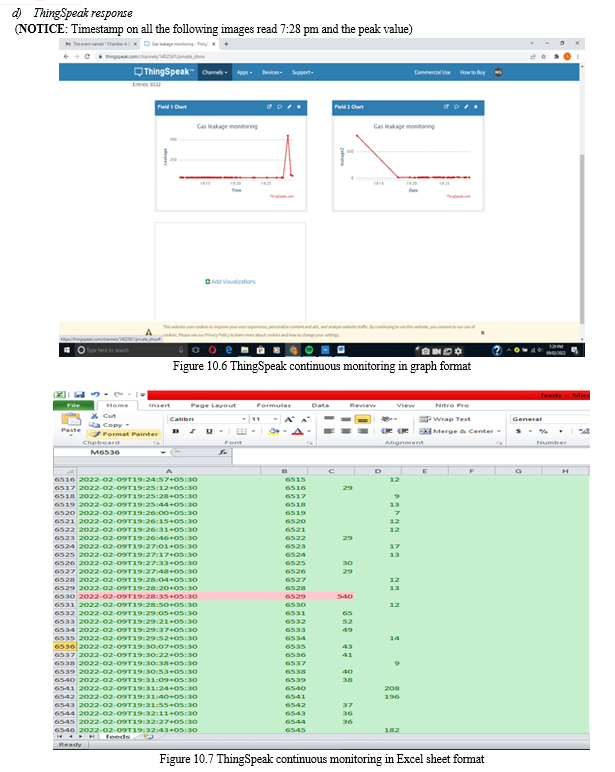
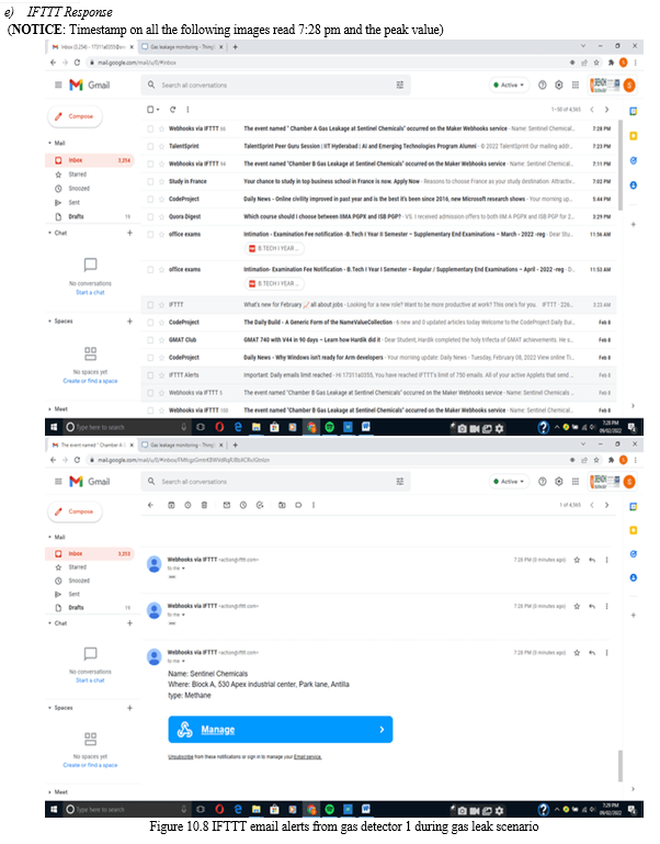
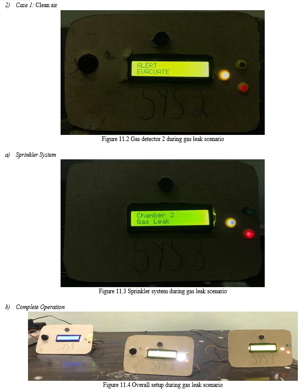
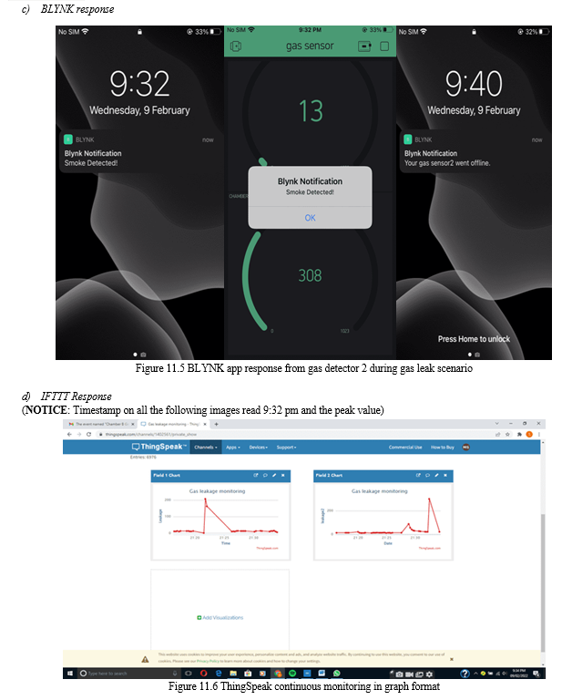
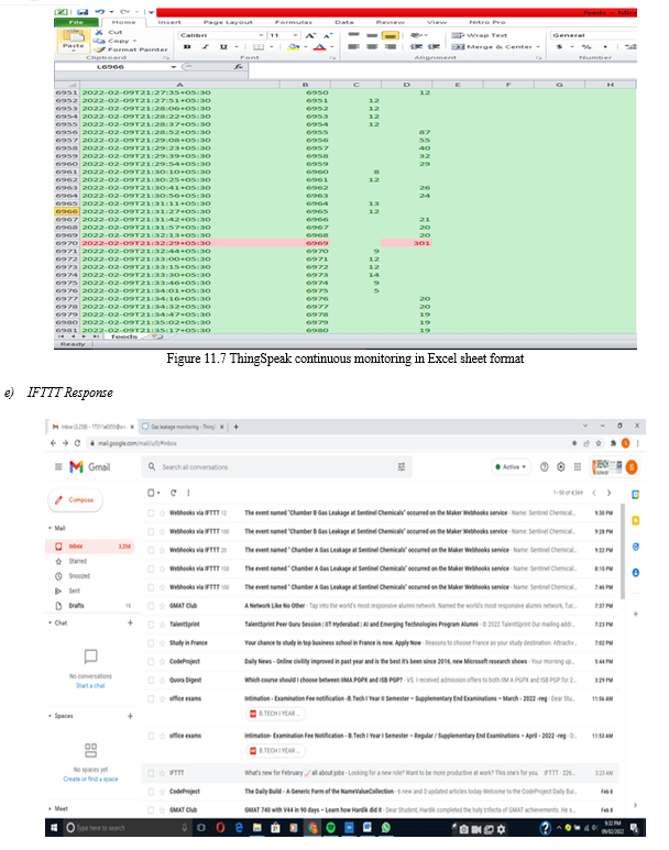
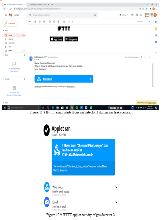
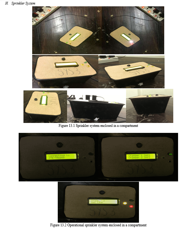
In addition, there are three IoT platforms present namely BLYNK, ThingSpeak, IFTTT. The people working in the organization i.e employees connected to the same Wi-Fi as the NodeMCU can monitor the presence of the gas in the meter, as shown in figure 10.5, by installing the BLYNK app. A notification is pushed when the concentration of the gas is above the threshold even when the app is closed. When the device containing the app has gone out of the Wi-Fi vicinity or cuts off from the Wi-Fi, a notification is pushed stating that the device has gone offline. When the gases shoot above the threshold level an email, as shown in figure 10.8, is pushed via Webhooks and the IFTTT IoT platform. The NodeMCU takes in data from sensors and posts on the ThingSpeak IoT analytics platform wherein the data is shown in a graph (Figure 10.6) and can be retrieved in excel (.csv) with the entry ID, timestamp present for every input. A similar system, as shown in figure 5.3, is created to demonstrate that data from multiple sensors, placed at various critical points, can be processed and viewed in one place without requiring the creation of separate channels for each system. The unified data is acquired from the ThingSpeak platform and is transferred to a NodeMCU which initiates the sprinkler system (relay interfaced with motor, shown in figure 5.4). The sprinkler system displays messages (figure 10.1) such as “Chamber 1 SAFE”, “Chamber 2 SAFE” and a green LED is switched on when no gases are present at the two locations. When gases are present at gas detector 1, the messages (Figure 10.3) show “Chamber 1”, “Gas Leak” and red LED, white LED are switched on. The white LED indicates that the relay is energized. Similarly, when gases are present at gas detector 2, the messages (Figure 11.3) show “Chamber 2”, “Gas Leak” and red LED, white LED is switched on. A relay is present on every microcontroller placed at the critical points. This relay operates a solenoid valve to direct the neutralizer agent, pumped by the sprinkler system, towards the point of the leak. A white LED is used to indicate the behavior of the relay. The systems are cased in a plastic compartment to give it a near product outlook conveying the compactness and definiteness.
IV. CIRCUIT DESIGN
V. SYSTEM DESIGN DESCRIPTION
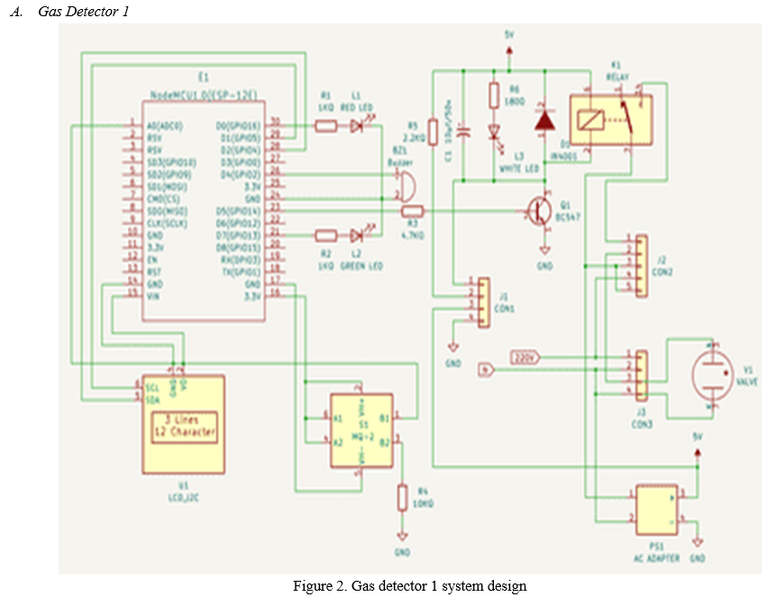
- NodeMCU supplies power to all the output peripherals (LEDs, LCD with i2c, buzzer, MQ-2 Sensor) as shown in figure 2.
- MQ-2 semiconductor was connected to analog pin A0 of NodeMCU. Power supply, GND to the sensor was given by 3.3v pin, GND pin of NodeMCU.
- The green LED, red LED was connected to the D7, D0 pin of NodeMCU respectively. Both LEDs had a 1KΩresistor, in series configuration, on their positive end.
- A piezo buzzer was connected to the D4 pin of NodeMCU.
- A common GND is created to accommodate negative terminals of LEDs and buzzer.
- An LCD with i2c was set up. The SCL, SDA pins of LCD with i2c were connected to the D1, D2 pin of NodeMCU respectively. The LCD with i2c draws up the power from Vin (5v) pin from NodeMCU and the GND pin of the LCD with i2c was connected to the GND port of NodeMCU.
- A relay circuit was created using the D5 pin of the NodeMCU. For governing the relay, a 5v supply is required. Hence the 3.3v of NodeMcU is coupled with an amplifier circuit. The D5 pin was connected to the base of the BC547 transistor with a 4.7KΩ resistor in series configuration. The emitter end was grounded. The collector end was connected to the positive pin of the magnetic coil and the negative end, with a 2.2 KΩ resistor in series configuration, was connected to a connector thereby completing the circuit.
- A 10μf / 50v capacitor, IN4001 diode was connected to the magnetic coil in parallel configuration. A LED, with a180Ω resistor in series configuration, was connected to a 10μf / 50v capacitor in parallel configuration. The LED acts as an indicator when the relay is energized.
- Through a series of connectors, the common pin of the relay is supplied with a 220v external power supply through an AC adapter. and the NO pin is connected to the solenoid valve with neutral in direct connection.
- The three IoT platforms namely BLYNK, ThingSpeak, IFTTT were interfaced with NodeMCU through the code. By incorporating the login credentials, the ESP8266 Wi-Fi module connects with the local network. The communication with every platform is mentioned below.
11. Blynk
- Blynk app was installed and the functions to be performed were defined through widgets.
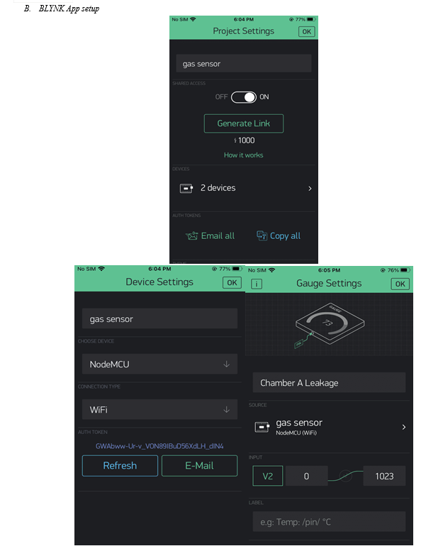
- A connection was established, as shown in figure 6, by defining a virtual pin (a pin that functions as a physical pin on the microcontroller) in the app settings and the authentication token was inserted, generated by the app when a project is created, into the code.
- Appropriate libraries were downloaded that allow the code to recognize the channel through which the data is to be transmitted.
12. IFTTT (if this, then that) - Applet creator
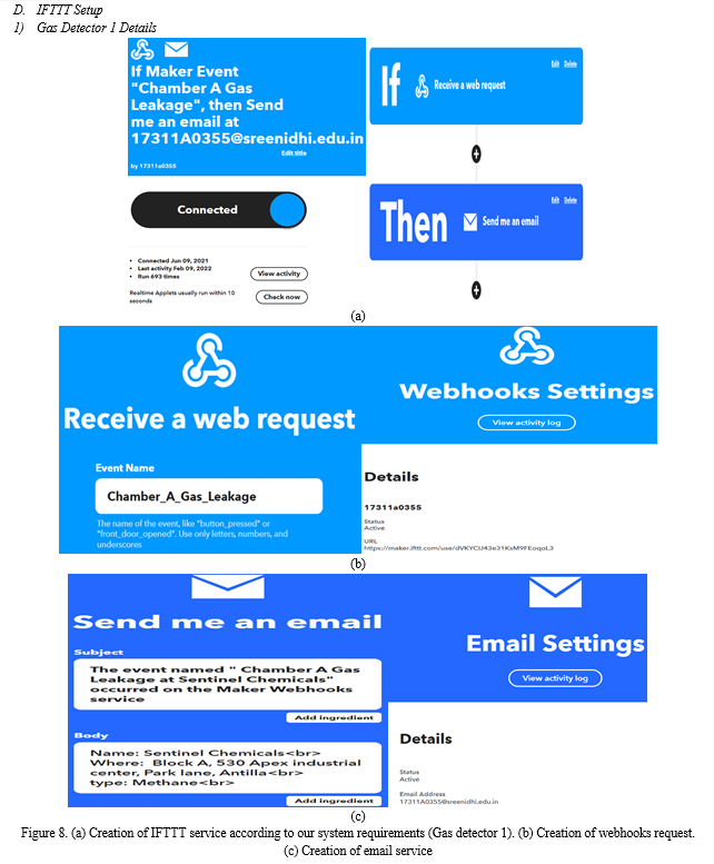
- In IFTTT, a Webhooks trigger was created, as shown in figure 8(b), and the following action of pushing an email was created in the next step as shown in figure 8(c).
- The Webhooks generated a trigger by creating a web request which consists of a key unique to the project.
- Libraries were used in the code to recognize and implement the trigger at the right time.
13. ThingSpeak (IoT analytics platform)
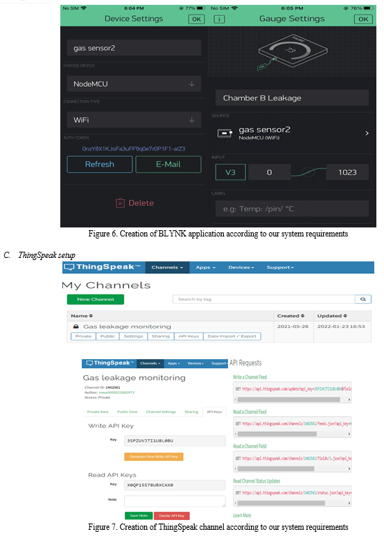
- A channel, as shown in figure 7, was created thereby creating a path for the user to publish the data.
- Based on the number of inputs to be published the fields that display the data in the graph were decided.
- The Application Programming Interface (API) key was inserted, generated by the platform when a channel is created, into the code.
- Appropriate libraries were downloaded that allow the code to recognize the channel through which the data is to be transmitted.
14.A charger (a cable connected to the socket and the male of the charger cable is interfaced with the female port of NodeMCU) was used to power the NodeMCU.
15. A similar system, as shown in figure 5.3, was developed to demonstrate that the data from multiple sensors can be collected, viewed on a single dashboard. The system is governed by the same protocols with only changes in paths to publish data on the IoT platform dashboard.
- Blynk- A new monitoring widget, as shown in figure 11.5 (bottom meter), was added to display the data. The software was notified of the inclusion of the new NodeMCU. A virtual pin was assigned to establish communication between the platform and the ESP8266 Wi-Fi module. An authentication code was generated which was embedded into the code.
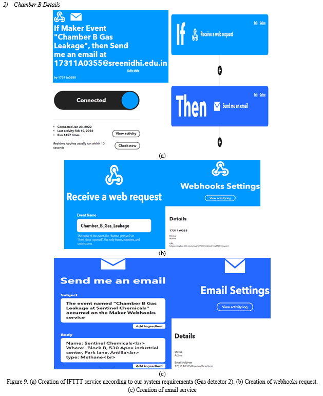
- IFTTT- Similar to the process mentioned above and the process is shown in figure 9.
- ThingSpeak- A new field, as shown in figure 11.6( Field 2 chart), was created in the existing channel. As for the code, the API key and the channel number remain the same but the data was directed to the dashboard by mentioning the appropriate field number.
16. The data from the ThingSpeak platform was transferred to another NodeMCU which initiated the sprinkler system. By incorporating the login credentials, the ESP8266 Wi-Fi module connects with the local network. The communication with the platform was established by giving instructions, such as the read API key and the channel number, to the NodeMCU.
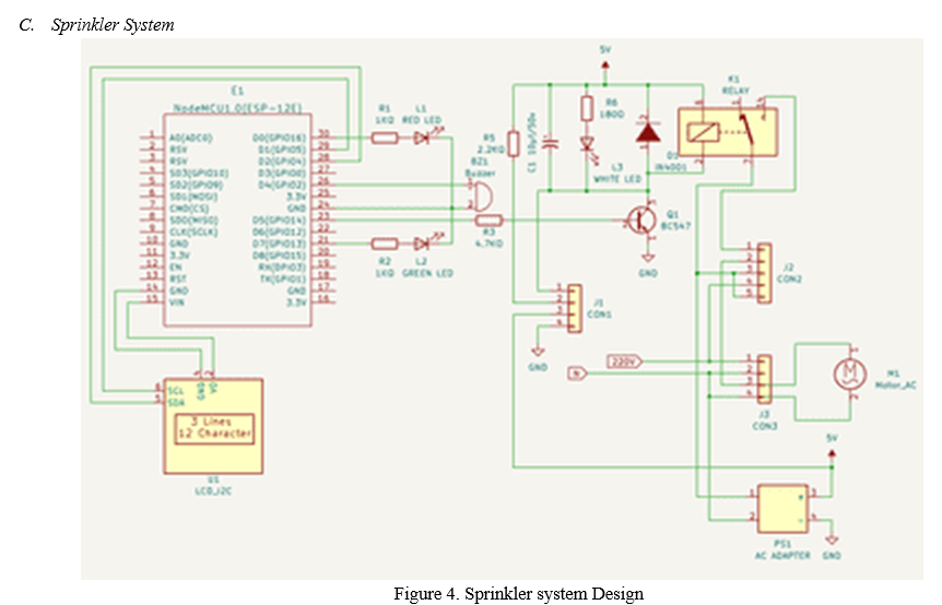
17. The sprinkler system, as shown in figure 4, architecture remains the same with only change is that the system uses an AC motor to pump the sterilizing agent to the required location.
VI. ALGORITHM
- Include the libraries through which the user communicates with physical peripherals or the IoT platforms and define the functions.
- For the implementation of the IoT platforms, a connection must be made with the local network and ESP8266 wifi module. Channels are established to export the data from the sensor to the IoT platform.
- Visualize how the system should behave in different situations, when deployed in the real-time environment, and develop scenarios that specify how a particular peripheral should function.
a. During clear air scenario (figure 10)
- The green LED is ON.
- The red LED is OFF.
- The buzzer is in the OFF state.
- The relay is in the OFF state thereby keeping the solenoid valve in standby state. Hence, the white LED is OFF.
- The display shows words such as “SAFE” and “ALL CLEAR”.
- The leakage can be monitored on both BLYNK (meter form) and Thingspeak (graph form).
b. During gas scenario (figure 10.2)
- The green LED is OFF.
- The red LED is ON.
- The buzzer is in ON state.
- The relay is in the ON state thereby energizing the solenoid valve. Hence, the white LED is ON.
- The display shows words such as “ALERT” and “EVACUATE”.
- An email is pushed through webhooks and IFTTT.
- BLYNK app, as shown in figure 10.5, pushes a notification.
- The changes in data are plotted in a graph, as shown in figure 10.6, on the ThingSpeak platform.
- The data can be downloaded in an excel format as shown in figure 10.7.
4. Irrespective of the scenario, monitoring features of Blynk, ThingSpeak publishes data round the clock but the user needs to define a particular scenario to enable the trigger feature of IFTTT and notify feature of Blynk.
5. Determine the response time (how fast data need to be transferred) and the action time of a particular component if it is triggered.
6. Multiple systems are developed using the above protocols with only changes in the paths for publishing the data onto a common platform.
7. The data from the sensor which is in analog format is sent to NodeMCU where the data is converted to digital format and the appropriate result is shown whether it be visual (LCD, LEDs), sound (buzzer), IoT platform (email, message, website), switching of the relay (solenoid valve).
7. A relay is interfaced with every NodeMCU present at different locations across the plant. The relay is used to operate the solenoid valve which is used to direct the neutralizing agent towards the leak.
A. Sprinkler System
- Include physical peripherals and associated libraries.
- A connection must be made with the local network and ESP8266 Wi-Fi module.
- Established channel addresses are to be mentioned to import the data from the IoT platform to the microcontroller.
- Based on the acquired data, develop scenarios that specify how a particular peripheral should function.
a. During Clear Air Scenario (Figure 10.1)
- The green LED is ON as it is normally closed (NC) switch type.
- The red LED is OFF as it is normally open (NO) switch type.
- The buzzer is in the OFF state.
- The relay is in the OFF state thereby keeping the AC motor in standby state. Hence, the white LED is OFF.
- The display shows words such as “Chamber 1 SAFE” and “Chamber 2 SAFE” when no leak is detected at both the detectors.
b. During Gas Scenario (Figure 10.3)
- The green LED is OFF.
- The red LED is ON.
- The buzzer is in ON state.
- The relay is in the ON state thereby energizing the AC motor. Hence, the white LED is ON.
- The display shows words such as “Chamber 1”, “Gas Leak” if there is a leak at gas detector1, and “Chamber 2”, “Gas Leak” if there is a leak at gas detector 2.
5. Determine the response time (how fast data need to be transferred) and the action time of a particular component if it is triggered.
6. The prime importance of this microcontroller is that during a leak, the NodeMCU (microcontroller) operates the sprinkler system by switching on an AC motor through the relay.
VII. RESULTS
VIII. APPLICATIONS
A. Vehicles using LPG Cylinders and even in households to detect leaks.
B. Chemical industries, offshore &onshore drilling sites, national pipelines, mines, scientific laboratories, power plants (nuclear, thermal, etc).
C. Mass transportation systems to facilitate safe commute.
D. At all sites where hazardous gases pose a significant threat.
IX. FUTURE SCOPE
A. An outer casing that is vibration, moisture, dust resistant must be designed.
B. Instead of relying on third-party IoT platforms, one can create and install our firewalls to make the system tamper-proof.
C. The system can be customized to detect any type of gas by changing the sensor appropriate to the application.
D. Multiple sensors can be incorporated to monitor multiple parameters in a single environment.
E. A standalone battery can be interfaced with the system which automatically functions during power outages/fluctuations.
X. ACKNOWLEDGMENTS
Firstly, I am grateful to Sreenidhi Institute of Science and Technology for allowing me to work on this project. I would like to thank my college guide Dr. P. Nitish Reddy of the mechanical department and professional guides Dr. Sree Rama Chandra Murthy Dasika and Dr. Satyanarayana Katukojwala for giving me their constant guidance, motivation throughout the period this course work was carried out. I would like to thank my friends K. Raja Prithvi and R.Yashwanth for helping me in creating the base model. A special thanks to Sreenath Reddy, for his ideas and support. I express my sincere gratitude to Prof. T. Ch. Shiva Reddy, Head of Department and Principal for helping me in carrying out this project and supporting me throughout my study at Sreenidhi Institute of Science and Technology.
Conclusion
I may infer that I have successfully built a system that is used to detect gas leaks. Under dangerous situations, the system worked admirably. Continued improvisation and sophistication might lead to a foolproof system that can be appropriately customized to function under various situations and applications. One should understand that such systems replace redundant and monotonous jobs and make human lives better by extending the boundaries of innovation.
References
[1] Mahalingam, A.; Naayagi, R.T.; Mastorakis, N.E. Design and implementation of an economic gas leakage detector. In Proceedings of 6th International Conference on Circuits, Systems and Signals, Athens, Greece, 7–9; pp. 20–24, Mar 2013. [2] Attia, H.A.; Halah, Y.A. Electronic Design of Liquefied Petroleum Gas Leakage Monitoring, Alarm, and Protection System Based on Discrete Components. Int. J. Appl. Eng. Res., 11, 9721–9726, 2016. [3] Apeh, S.T.; Erameh, K.B.; Iruansi, U. Design, and Development of Kitchen Gas Leakage Detection and Automatic Gas Shut-off System. J. Emerg. Trends Eng. Appl. Sci. 2014, 5, 222–228. Eng. Proc., 2, 28, 2020. [4] Soundarya, T.; Anchitaalagammai, J.V.; Priya, G.D.; Karthickkumar, S.S. C-Leakage: Cylinder LPG Gas Leakage Detection for Home Safety. IOSR J. Electron. Commun. Eng., 9, 53–58, 2014 [5] Shrivastava, A.; Prabhaker, R.; Kumar, R.; Verma, R. GSM-based gas leakage detection system. Int. J. Emerg. Trends Electr. Electron., 3, 42–45, 2013 [6] Anurupa, A.; Gunasegaram, M.; Amsaveni, M. Efficient Gas Leakage Detection and Control System using GSM Module. Int. J. Eng. Res. Technol.,3, 1–4, 2015. [7] Meenakshi, A.A.; Meghana, R.B.N.; Krishna, P.R. LPG Gas Leakage Detection and Prevention System. Int. J. Future Revolut. Comput. Sci. Commun. Eng. 2017, 3, 1–4. [8] Angela Casauay, \\\"Bomb? Gas? Remember the Glorietta blast?\\\", 2013 [9] Jenifer, M. Keerthana and P. Kumar, Hazardous Gas Detection and Alerting Using Sensors, 2017.
Copyright
Copyright © 2022 Mourya Sirapu . This is an open access article distributed under the Creative Commons Attribution License, which permits unrestricted use, distribution, and reproduction in any medium, provided the original work is properly cited.

Download Paper
Paper Id : IJRASET40358
Publish Date : 2022-02-15
ISSN : 2321-9653
Publisher Name : IJRASET
DOI Link : Click Here
 Submit Paper Online