

Ijraset Journal For Research in Applied Science and Engineering Technology
Design and Fabrication of Motorized Hydraulic Jack System
Authors: Durvesh Rohidas More, Aditya Arun Patil, Adesh Ananta Thakare, Nishank Rajesh Vartak, Md Saqib Ansari
DOI Link: https://doi.org/10.22214/ijraset.2022.41445
Certificate: View Certificate
Abstract
A jack is a mechanical lifting device used to apply great forces or lift heavy loads. A mechanical jack employs a screw thread for lifting heavy equipment. A hydraulic jack uses hydraulic power. In the case of tyre puncture or replacing wheels lift the car is more important part. This time we use traditional ways to lift the tyre. In that case a physically handicapped person, older person aged person not lifts the tyre easily. They require more time and also require more force to lift the tyre. In that way to help those who are physically challenged, aged person this project automatic hydraulic jack system is more useful. So, we tried to grab the opportunity. Here we use a wiper motor to drive the hydraulic jack loading subsequently and automatically.
Introduction
I. INTODUCTION
The most common form is a car jack, floor jack or garage jack, which lifts vehicles so that maintenance can be performed. Jacks are usually rated for a maximum lifting capacity for example, 1.5 tons or 3 tons. Industrial jacks can be rated for many tons of load. A revolutionary change has taken place in the field of fluid power technology due to the integration of electronics as a control medium for hydraulic components and system. Efforts have been made to include the latest possible trends in the field of hydraulics and allied control areas to keep the over changing state technology in hydraulics. In the case of tyre puncture or replacing wheels lift the car is more important part. This time we use traditional ways to lift the tyre. In that case a physically handicapped person, Unskilled person or aged person not lifts the tyre easily. They require more time and also require more force to lift the tyre. In that way to help those who are physically challenged, ladies or aged person this project automatic hydraulic jack system is more useful. So, we tried to grab the opportunity. Here we use wiper motor to drive the hydraulic jack loading subsequently and automatically. Our project works on the mechanism of converting rotary motion of the wiper motor into reciprocating motion of the hydraulic jack plunger. A cylinder cage structure of wiper motor ensures maximum power delivered by consuming the available battery power which can be easily generated. Important thing is that power is available at instant and anyone can withdraw easily, without any hazard. Battery is also available in any car so when our external battery will be discharge then we use power in the car.
II. LITERATURE REVIEW
Kevin Simmonds, Lovedale Crescent et.al. (NOV 30, 1999) [1] As the report suggest after conclusion A motorized jack for reducing the amount of labour needed to lift up a vehicle. The motorized jack includes a housing with a motor provided in the housing. A threaded shaft is also provided in the housing. A top end of the threaded Shaft is upwardly extended through a hole in the top of the housing. A ring gear is disposed around the threaded shaft. The ring gear has a toothed inner perimeter engaging the threaded shafts. An interconnected Set of gears is provided in the housing to connect the ring gear to a rotating shaft of the motor. A lifting head is coupled to the top end of the threaded shaft.
Dennis E. Farmer et.al. (May 29, 2001) [2] an automatic jack and wheel change System having at least one inverted jack driven by an electric motor permanently attached to the vehicle. The System may employ a jack disposed between the front and rear wheel on each side of the vehicle, or it may be equipped with a jack at each of the four wheels.
The system also features a novel wheel and hub-axle assembly featuring a split axle whose length may be adjusted by operation of an electric motor. The hub has a plurality of arms extending from the hub in a Star-shape, each arm having a finger at its free end. The wheel has a plurality of slots defined therein so that the wheel may be removed by aligning the slots with the arms on the hub and pulling the wheel off when the axle is extended, and a plurality of holes defined therein for receiving the fingers to lock the wheel on the hub when the axle is retracted. Both the motor for raising the jack and the motor for adjusting the length of the axle may be operated by remote control.
Bhavesh B Pipaliya et.al. (JAN 2014) [3] is published by According to this project Power screws are used to convert rotary motion into translator motion. A screw jack is an example of a power screw in which a small force applied in a horizontal plane is used to raise or lower a large load. The principle on which it works is similar to that of an inclined plane. The mechanical advantage of a screw jack is the ratio of the load applied to the effort applied. The screw jack is operated by turning a lead screw. The height of the jack is adjusted by turning a lead screw and this adjustment can be done either manually or by integrating an electric motor, which is controlled by remote. In this work, an electric motor will be integrated with the screw jack and the electricity needed for the operation will be taken from the battery of the vehicle and thereby the mechanical advantage will be increased. And the motor will be controlled via remote from a short distance.
Ivan Rout et.al. (May 2014) [4] As they suggest in Project With the increasing levels of technology, the efforts are being put to produce any kind of work that has been continuously decreasing. The efforts required in achieving the desired output can be effectively and economically be decreased by the implementation of better designs. Power screws are used to convert rotary motion into reciprocating motion. An object lifting jack is an example of a power screw in which a small force applied in a horizontal plane is used to raise or lower a large load. In this fabricated model, an electric motor will be integrated with the object lifting jack and the electricity needed for the operation will be taken from the deck battery and thereby the mechanical advantage will be increased.
Choudhary S., Ravi Kumar D, et.al. (JAN 2016) [5] According to their idea of project, Car jack comes with vehicle require users to apply manual force to lift a vehicle. This paper is targeted to analyse the development in existing scissor car jack in order to make load lifting easier by utilizing Car battery (12V) which can be used in emergency situations. In this design, the cigarette lighter receptacle point is connected in car, which drives the power from the car battery (12V), this will run the DC motor and thus connected power screw is rotated. By this, the car jack will lift the vehicle. The contractions or expansion movement of car jack can be controlled by a joystick as per requirements. This modified car jack can be easily operated by any person and it saves time, hence reduce wastage of human efforts and time. The design of this car jack is being developed in Solid Works 2010 software. Manufacturing and fabrication work have been done using milling, drilling, grinding and threading machines. The modified car jack is tested and implementing of design can solve ergonomics problems.
Timur Chobani Khadar et.al. (JAN 2017) [6] His experience about project is the tire puncture problem of the cars on the roads, especially on the highway roads generally needs manual human force to solve the problem by using a mechanical scissor car jack. Our work focused on a bottle carjack and adapting D.C. motor (12 volts) with chain sprocket set to design a suitable machine. Lifting the car to solve the puncture problem with this new machine is easier, safer, abbreviate the time and more reliable for persons who suffer from their health’s. We used drilling, Nd welding machines to make up this work. The designed jack had been tested on a passenger car and passed successfully. they used Solid works software program to achieve the goal.
Asst Prof. Anand A. Kulkarni, Avinash V. Roy et.al. (SEP 2017) [7] As they concluded from this A jack is a device which is used to raise part of vehicle in order to facilitate vehicle maintenances or breakdown repairs. In normal jack system a mechanical jack is used for lifting the vehicles. The most common form is a car jack, garage jack, floor jack which lifts vehicles so that maintenance can be performed. Jacks are generally used to increase mechanical advantage (lifting the vehicle). Generally, jacks undergo buckling when they reach maximum load conditions (as per the tests conducted by consumer affairs). For this reason, we have to develop the system which can use toggle jack which is automatic in operation using electric motor. Vehicle’s battery can be used as a source of power for this motor. Our research in this regard reveals the facts that mostly some difficult methods were adopted in lifting the vehicles for reconditioning. This paper attempts to overcome this difficulty and a suitable device is to be designed such that the vehicle can be lifted from the floor without any application of impact force. The operation remains to be an essential part of the system although with changing demands on physical input, the degree of mechanization is increased.
III. METHODOLOGY
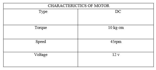
Method of making hydraulic jack Axel jacks as that term is commonly used are vertically operating jacks which comprise a hydraulic cylinder mounted on a base, the cylinder being short enough to permit the jack to be slid between a supporting surface and the axel of an automotive vehicle. Torque required to keep up and down motion of connecting rod is 45rpm hence 12volts DC motor of wiper system has been used. Circular crank is attached to the motor having 15cm diameter from centre hub. This crank is fixed with connecting rod with total 55cm length.
The operation of hydraulic jack depends on ?Pascal ‘s law. A change in pressure at any point in an enclosed fluid at rest is transmitted undiminished to all points in the fluid. Pressure exerted on a fluid in an enclosed container is transmitted equally and undiminished to all parts of the container and acts at right angle to the enclosing walls. Alternate definition: The pressure applied to any part of the enclosed liquid will be transmitted equally in all directions through the liquid.
|
S. No |
Component |
Material |
Reason/ purpose |
|
1 |
Hydraulic Jack |
Steel/Plastic/Rubber |
To lift the vehicles |
|
2 |
Crank |
Mild Steel |
Convert Rotational Force to Linear Force |
|
3 |
Connecting rod |
Mild steel |
Connecting to jack with crank |
|
4 |
Base Frame |
Mild steel |
Work as Stand |
IV. DESIGN OBJECTIVE
The basic objectives of the projects are:
- To increase simplicity of jack operation
- To increase the capacity
- It must be low in cost and commercially viable for all people.
- Increasing the speed than regular speed
- To get low maintenance
- To avoid manual power for operating the jack. A sincere attempt is made to accomplish almost all objectives as mentioned above and make it practically feasible.
V. THE MAIN COMPONENTS ARE AS FOLLOWS
- Hydrualic Jack: A Hydraulic jack consists of a cylinder and piston mechanism. The movement of piston rod is used to raise or lower the load. And secondly Mechanical jacks. They are either hand operated or power driven. They have further components like ram, plunger
- Motor: The motor is DC type of motor with 12 volts power which gives 45rpm speed, which is efficient to lift the vehicles from ground.
- Crank: It can be used to convert circular motion into reciprocating motion, or vice versa. The arm may be a bent portion of the shaft, or a separate arm or disk attached to it.
- Connecting Rod: When crank combined with a connecting rod, it can be used to convert circular motion into reciprocating Motion, or vice versa.
- Battery: Acid lead battery with capacity 35A provides nominal Voltage of 12V
- Switch: To operate the operation in one press switch is used to closed and open the circuit from battery with motor hence Jack will be stop.
- LED Strip: For Better visualization and handling the operation during night time
- Base Frame: All of the above components are assembled with this base to achieve the goal.
VI. CALCULATIONS
Assumption for design and calculations
Assumptions are as follows: -
Load = 6 ton
Operating Pressure = 25 MPa
Lift range of jack = 10 cm
Permissible tensile stress of mild steel (it) = 120 N/mm2
Permissible shear stress of mild steel (τ) = 20 N/mm2
Permissible compressive stress of mild steel (σc) = 20 N/mm2
Permissible compressive stress of cast iron (σCI) = 120 N/mm2
Permissible shear stress of cast iron (τCI) = 35 N/mm2
Modulus of elasticity of mild steel (E) = 210 GPA
Design of ram:
According to design catalogue, for 6-ton weight pressure will be 25 MPa
Here we know that,
Operating pressure = Force/Area
25=(6000*9.81)/(π/4)*D2
D2= 6000*9.81*4/3.14*25
D2=2999.2356
D=54.7 mm
Height of Ram = Lift of ram + clearance = 100 + 20 = 120 mm
A. Calculations For Design Of Ram Cylinder
It is a cylinder in which produces a slide way to ram. The ram cylinder is made up of mild steel with density of 7.888 gm./cm. It is mounted on base plate.
Let, inner diameter of ram cylinder (d) = 55 mm
Thickness of ram cylinder (t) = 10 mm
Outer diameter of ram cylinder (D) =d+2(t)
=55+2(10)
=75 mm
Height of ram cylinder = ram height + oil store clearance
=120+30
=150 mm
Design of plunger cylinder: -
The plunger cylinder is made up of mild steel and is mounted on the base plate. It provides slide way to the plunger in order to build up pressure.
Let, inner diameter of plunger cylinder (dp) = 8 mm
Thickness of plunger cylinder (tp) = 5 mm
By using Thickness and inside diameter. We can calculate outer diameter of plunger cylinder.
Dp=dp+2tp
=8+2(5)
=18mm
B. Design of Plunger
Plunger is made of mild steel which reciprocates in plunger cylinder to increase the press of oil.
Let, load acting (w) = 6 ton
Diameter of plunger (DP) = 8mm
We have,
Load acting on = pressure * area
Plunger=25* π/4* (8)2
=1256 N
= 1256/9.81
=128.03 kg
We take load acting on plunger = 130 Kg
Plunger displacement: -
We have, plunger displacement (pδ) = velocity ratio (VR)
Here, velocity ratio (VP) = Area of ram/Area of plunger
= 2348.79/50.24
=46.75
Plunger Displacement (pδ) =46.75 mm
=47mm
Height of plunger=clearance + plunger displacement
=47 + 47
=94mm
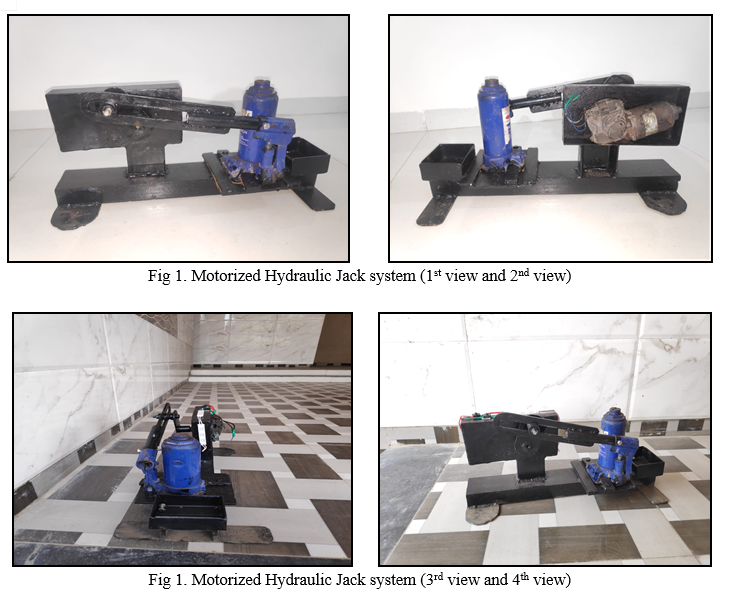
VII. OBSERVATIONS AND RESULT
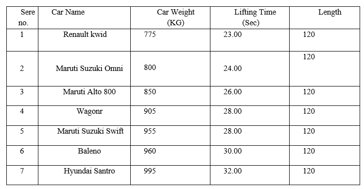
This chapter contains the implementation details of the motorized hydraulic system and the overview of the project along with the results and working of the system. As the project is on bit hydraulic jack, we always need testing to make it successful. If each component work properly in all respect and gives desired output for all kind of inputs then project is said to be successful. Comparing with mechanical Jack our project helps to save more time and manpower during lifting the car the project construction is simple and compact it is easy to installation and easy to carry power project power is applicable for the cars whose ground clearance is is nearly about 120 mm and car weight should be
VIII. ACKNOWLEDGEMENTS
We take the chance to direct our sincere thanks and gratitude to Hon. Principal, Prof. Dr. Aqeel Ahmed Shah and Management of Theem College of Engineering, for providing motivation and much support throughout our project work. We would like to gives our heartfelt thanks towards our Prof. Saqib Ansari for his help, guidance, and encouragement, during the Project. Also, we are heartily thankful to all Lecturer in Engineering and professors in the Mechanical Department. We were motivated by the encouragement of our professors and this made us complete our work under their oversee.
IX. CONFLICT OF INTERESTS
The authors declare that there is no conflict of interests regarding the publication of this article.
Conclusion
Object lifting jacks are the ideal product to push, pull, lift, lower and position loads of anything from a couple of kilograms to hundreds of tonnes. The need has long existed for an improved portable jack for automotive vehicles. it is highly desirable that a jack become available that can be operated alternatively from inside the vehicle or from a location of safety off the road on which the vehicle is located. Further, it should be stable and easily controllable by a switch so that jacking can be done from a position of safety. It should be easily movable either to a position underneath the axle of the vehicle or some other reinforced support surface designed to be engaged by a jack. Thus, the product has been developed considering all the above requirements. This particular design of motorized automated object lifting jack will prove to be beneficial in lifting and lowering of heavy loads.
References
[1] Aqeel, “Design of machine elements”, 3rd Edition, Tata McGraw Hill, 2010 [2] Rajendra Karwa, “A text book of machine design”, 2nd Edition, Laxmi Publications, 2006. [3] “A textbook of Automobile Engineering” by Dr.Kripal Signh Volume 1 and 2 [4] R.S.Khurmi and J.K.Gupta, “A text book of Machine Design”, 25th edition, s.Chand, 2005. [5] Robert L.Boylestad “Electronic devices and circuits, 10th Edition”, Pearson Publication, 2009. [6] Rodriguez, Daniel G \"Automatic Jacking System for an Automotive Vehicle\" U.S. Patent Number 6,991,221, 2006. [7] M.M. Noor, K. Kadirgama and M.M. Rahman, “Analysis of Auto Car Jack”, National Conference in Mechanical Engineering Research and Postgraduate Students, FKM Conference Hall, UMP, Kuantan, Pahang, Malaysia, 26-27 May 2010 [8] Mohd Abuzaid, Mohd Hasnain, Shabaj Alam, Sohail Khan and Surendra Agarwal, “Inbuilt Hydraulic jack in Automobile vehicles, International Journal of Innovations in Engineering and Technology”, 2 Feb 2013 [9] Prashant Kumar Srivastav, Vipin Kumar Pandey, Shailesh Kumar Maurya, Ajit Tiwari, Jawed Rafiq and S.K. Dwivedi, “Highly Efficient Motorized Screw Jack, International Journal of Computational Engineering Research”, 3 May 2013. [10] Mosley, David J, \"Vehicle Mounted Hydraulic Jack System\" U.S. Patent Number 5,377. [11] Mueller, Pamela and Thomas L. Mueller, \"Built In-Power Jack” U.S. Patent Number 4,993,688
Copyright
Copyright © 2022 Durvesh Rohidas More, Aditya Arun Patil, Adesh Ananta Thakare, Nishank Rajesh Vartak, Md Saqib Ansari. This is an open access article distributed under the Creative Commons Attribution License, which permits unrestricted use, distribution, and reproduction in any medium, provided the original work is properly cited.

Download Paper
Paper Id : IJRASET41445
Publish Date : 2022-04-13
ISSN : 2321-9653
Publisher Name : IJRASET
DOI Link : Click Here
 Submit Paper Online